Axis Coverage Shapes for Microsoft® Visio®
Axis Coverage Shapes for Microsoft® Visio® provides interactive 2D CAD security camera models to use in Microsoft® Visio®. The camera models can be placed into a floorplan inside Visio to visualize camera coverage and integrate surveillance system planning into your designs.
This manual is based on Microsoft® Visio® Standard 2016. Menu options might differ in other Visio versions.
Using the Axis Coverage Shapes for Microsoft® Visio® is subject to Axis General Software License Terms.
Getting Started
Download the files
This manual is based on the assumption that you are familiar with Microsoft® Visio®. If you need help using Visio, refer toMicrosoft® Visio® help.
Download the zip file for Axis Coverage Shapes for Microsoft® Visio® from axis.com/tools/axis-coverage-shapes
Extract the files on your local drive (C:) to Documents\My Shapes.
Add Coverage Shapes to Visio
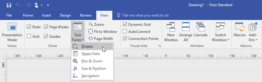
Open Microsoft® Visio® and open the Shapes task pane.
If it’s not open or not visible, go to View > Task Panes and select Shapes.
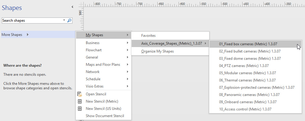
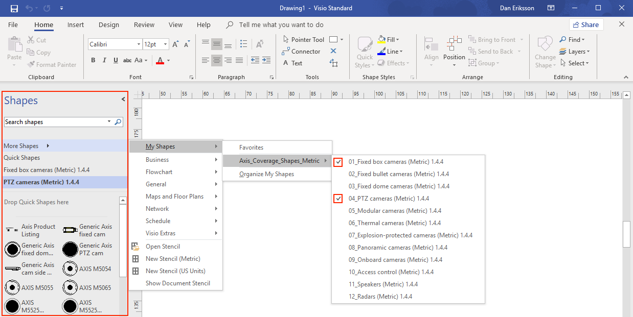
In Shapes, select More Shapes > My Shapes where you can select the group or groups of Coverage Shapes you downloaded.
When prompted, select Trust all from publisher or alternatively Enable Macros in the Microsoft® Visio® Security Notice. You need to enable macros to be able to use the Coverage Shapes.
You’ll now have the selected camera families available in the Shapes task pane.
Import a floorplan
Designing a system in Microsoft® Visio® usually starts by importing a floorplan.
Before you start
Check out our tool tips for Measuring tools and Scaling.
Import a CAD drawing
- Verify the scale of the AutoCAD file
To verify or change the scale of the AutoCAD file before the file import, open the Plot dialog in AutoCAD and note or change the scale. For more information, refer to related AutoCAD tutorials.
- Import the AutoCAD file to work with
To import an AutoCAD file, open Microsoft® Visio® and go to Insert > CAD Drawing. Select the file to import and click Open.
In the CAD Drawing Properties dialog, set the CAD drawing scale parameters and make sure that the Lock size and position and Lock against deletion checkboxes are selected.
If you are experiencing issues with the file import to Microsoft® Visio®, try saving the AutoCAD file as R14/LT98/LT97-drawing. For more information, refer to related AutoCAD tutorials.
- Assign a camera layer to the image
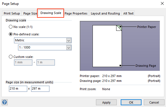
Before adding cameras, make sure to double check the scale of the imported floorplan. Go to Design > Page Setup > Drawing scale to verify or change the defined scale.
Go to Home > Editing > Assign to Layer and create a new layer that will serve as a layer for the cameras to add. Go to Home > Editing > Layers > Layer Properties, select the newly created layer and mark this layer as Active layer.
Import a PDF file
PDF files are not ideal to work with as they are not vector files. We recommend you to use an online tool, such as Microsoft® PDF to JPEG application to convert PDF files to image files, or to take a snapshot of the PDF floorplan to save it as an image file.
- Import the PDF image to work with
To import a PDF file, open Microsoft® Visio® and go to Insert > Object > Adobe Acrobat Document.
Select the file to import and click Open.
After the import is done, make sure to fit the imported PDF image into a single page in Microsoft® Visio®.
If you need to rotate the image, go to Home > Arrange > Position.
Mark the imported floorplan and go to Home > Arrange > Group and select Ungroup.
- Define the scale of the PDF image.
To be able to define the scale of the image, use the Measuring tool.
Once measuring is done, open a new page in Microsoft® Visio® and go to Design > Page Setup > Drawing scale to enter the defined scale.
- Assign a camera layer to the image
Go to Home > Editing > Assign to Layer and create a new layer that will serve as a base layer to your floorplan. To lock the plan in place, go to Home > Editing > Layers > Layer Properties, select the newly created layer and select the Lock checkbox.
Repeat this step to create another layer for the cameras to add. In the Layer properties dialog, mark this layer as Active layer.
Now you can start adding cameras to your PDF floorplan image.
Import a Map image
Instead of importing a map image into Microsoft® Visio®, we recommend you to try the maps feature in Site Designer, which offers a smooth and reliable workflow using the integrated map functionality.
Adding Cameras
Before you start
Axis provides regular updates to this offering, make sure you always start by downloading the latest version from axis.com/tools/axis-coverage-shapes.
Once the layer for cameras is defined in your floorplan, go to More Shapes > My Shapes and select the desired families. Repeat this step to all camera families you want to load into your design.
To add a camera model to the floor plan, browse the selected camera families and drag-and-drop to the models into the drawing.
Modify the default camera models settings in your floorplan according to your design.
To control the camera model’s Field of View (FOV) settings, use the yellow toggle handles within the model. The provided data fields will change as the FoV is repositioned.
To change the parameters of the camera model, right-click the camera model and select Edit Shape Data option where you can adjust most of the camera attributes.
To edit the displayed text for the camera model, right-click the camera model and select Edit Text. Update the name of the camera model and click Esc on your keyboard.
To copy an existing camera model into other locations within the same floorplan, right-click the camera model and use the Copy and Paste options.
To add a camera schedule for the camera models in your floorplan, drag-and-drop the Axis Product Listing stencil into the drawing. The stencil will include by default the already placed models in your floorplan. To edit the displayed text in the listing, right-click the text field and select Edit Text. Once your changes are added, click Esc on your keyboard.
Export to Site Designer
To be able to continue working with your design plan, you can export your complete floorplan and camera models into AXIS Site Designer.
Save your drawing in Microsoft® Visio®.
Right click any camera in your drawing and select Export all Cameras
In the Export Cameras dialog, click Export to Axis Site Designer. When the export is done, a pop up dialog is shown with the export file location. Click OK.
- Note
From this dialog you can also export your project as a comma separated file into other planning tools (for example Microsoft Excel). Make sure to select Comma as a separator before you click Copy to Clipboard.
Open Site Designer and select Import project.
Browse to your .asdp / .asdpx file you wish to import and click Open. You get a notification in Site Designer once the import is completed.
For more information about AXIS Site Designer, go to https://www.axis.com/tools/axis-site-designer/overview.
Tooltips
This section includes a few useful ideas to help you using Microsoft® Visio®. We recommend you to refer to Microsoft® Visio® support pages for more details and tooltips.
Creating templates
You can create Microsoft® Visio® templates for a specific paper size to help you quick starting your projects. Use the “Save As” command to ensure you are not making changes to the original template.
Additional pages in Visio
- Follow these steps to add a new page in Microsoft® Visio®:
In the drawing area, scroll to the bottom of the page and click on the cross sign to Insert page.
To copy your existing drawing into the new page, select (Ctrl + A) and copy (Ctrl + C) your drawings and paste them in the new page (Ctrl + V).
To rename the page, right click the new page you created and select Rename.
Measuring tools
To help your projects with scaling, use the measuring tools in Microsoft® Visio®.
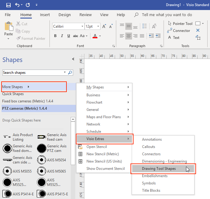
To add the measuring tools to the Shapes tool pane, go to Shapes tool pane > More Shapes> Visio Extras > Drawing Tool Shapes
Select Horizonal measure and Vertical measure from the available tools.
To add measuring tools to your Favorites, right-click Horizonal measure and / or Vertical measure in the Shapes tool pane and select Add to My Shapes > Favorites.
Scaling
When the drawings you create contain real-world objects that are larger than a printed page you need to draw to scale. We recommend you to determine the scale of a drawing prior to importing a floorplan.
Go to File > New and create a new project.
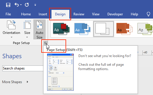
In the Design tab, go to Page Setup (Shift + F5) to open the full set of page formatting options.
In Page Setup, go to Drawing Scale and enter the pre-defined scale details and/or the page size
For more information on scaling, refer to the Microsoft® Visio® online help.
Project transfer from Microsoft® Visio® to AXIS Site Designer
What is the benefit of using AXIS Site Designer compared to Coverage Shapes in Microsoft® Visio®?
Compared to licensed products like Microsoft® Visio®, using a free online tool, such as AXIS Site Designer for planning your design has several advantages.
You always up to date with our latest product offering
You get a comprehensive project documentation, including bill of materials, bandwidth estimate, system proposals and installation reports.
You can easily browse and add new products or system accessories with the help of the built in product and accessory selector
Designing sites including VMS setup, camera placement and Field of View limits are easy and simple.
You can import camera and recording settings into your VMS and able share notes and installation instructions with installers.
Read more about AXIS Site Designer on axis.com or browse our manual for more information.
How do I move my existing Visio® project into Site Designer?
To be able to start using AXIS Site Designer with your existing projects created with the help of Axis Coverage Shapes for Microsoft® Visio®, you need to export your camera listings and drawings such as floorplans to AXIS Site Designer.
To export all your camera listings, refer to Export to Site Designer
To import your drawing from Microsoft® Visio® to Site Designer, follow these steps:
To hide all field of views on your drawing, right click any camera in the project and remove the Show FOV check mark.
In Microsoft® Visio®, go to File > Export > Change file type > PNG.
Click Save As and browse to a folder location where you want to save your exported file.
Go to sitedesigner.axis.com and login to AXIS Site Designer.
From the My projects list, go to the project that includes your recently imported camera listings from your Visio project.
Open your project, go to Maps > Add new map > Upload floor plan.
Browse to the .png file you exported from your Visio project.
Set the scale for the image (same as you used in your Visio project) and place the cameras that you already imported from Visio.
You are all set to work with your newly imported project in AXIS Site Designer. To learn more about how to work with AXIS Site Designer, go to axis.com or browse our online manual for more information.