About your device
AXIS Camera Station S22 Appliance series is an all-in-one recording solution with integrated, manageable PoE switch designed to deliver reliable high-definition surveillance with up to 4K resolution. For quick and easy installation, the appliance series is preconfigured and preloaded with AXIS Camera Station video management software including licenses plus all necessary system software. AXIS Camera Station offers an intuitive user interface that allows users to take full advantage of Axis wide range of video surveillance cameras and other IP products. With the operating system stored on a solid-state drive (SSD) and 5-year hardware warranty, the appliance series provides a reliable surveillance solution.
An AXIS Camera Station S22 Appliance consists of two parts:
Switch: Built-in Power over Ethernet (PoE) switch.
Computer: Preloaded with all necessary software you need to create a surveillance solution including the video management software AXIS Camera Station.
The switch and computer are two separate parts.
The switch and computer communicate through the internal uplink connectors: one is located on the switch Power Circuit Board and the other is located on the computer motherboard.
The server uplink U2 is an external network interface that can connect to an existing network.
Devices connected to server uplink U2 can not communicate with devices connected to the switch directly.
Devices connected to server uplink U2 can communicate with devices connected to the switch through AXIS Camera Station.
Setup examples
Setup in an independent surveillance network
You can create an independent surveillance network which has no interconnectivity to another external network. This setup is a basic plug and play installation. The built-in switch’s DHCP server is enabled by default. As soon as you plug the cameras into the PoE ports, the cameras will power on and obtain an IP address and be accessible via AXIS Camera Station.
| Difficulty level | Basic |
| Benefits | Dedicated surveillance network with no interconnectivity to another external network Plug and play installation |
| Limitations | Bandwidth PoE budget No remote access |
| Actions needed | Change the default password for the built-in switch Register the AXIS Camera Station license |
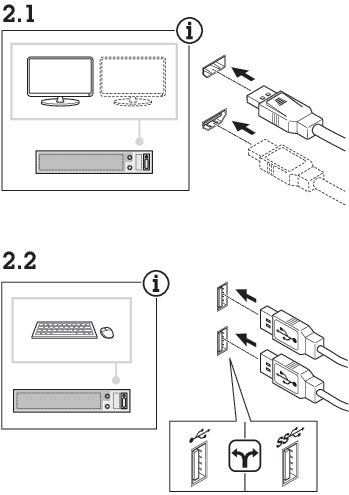
| Connectors used | PoE enabled network connectors, port 1-12 USB 2.0 connector x2 (for keyboard and mouse) DisplayportTM or HDMI connector |
| Connectors NOT used | RJ45 switch uplink (U1) SFP switch uplink (U1) RJ45 server uplink (U2) USB 3.0 connector (front side) Audio line in (front side) Audio line out (front side) |
Setup in an existing network
You can create a surveillance network within an existing network. This means that the surveillance network is separated from the existing network.
When you use an additional recorder, for example, the AXIS S30 Recorders, the appliance does not route network data from the surveillance network to the server network for recording. Make sure that the AXIS S30 Recorders are connected to the same network as the cameras.
| Difficulty level | Advanced |
| Benefits | Ability to use an AXIS Camera Station client to connect to S22 series over the network. Network segregation |
| Limitations | May require you to follow corporate network polices |
| Actions needed | Change the default password for the built-in switch Register the AXIS Camera Station license |
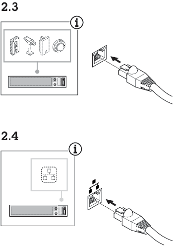
| Connectors used | PoE enabled network connectors, port 1-12 RJ45 server uplink (U2) for connection to network (Optional) USB 2.0 connector x2 (for keyboard and mouse) (Optional) DisplayportTM or HDMI connector |
| Connectors NOT used | RJ45 switch uplink (U1) SFP switch uplink (U1) USB 3.0 connector (front side) Audio line in (front side) Audio line out (front side) |
Get started
The standard workflow to configure an AXIS Camera Station recorder is:
Configure Windows®. We recommend to:
Update Windows® to the latest version. See Update Windows®
Create a standard user account. See Create a user account
Update AXIS Camera Station to the latest version.
If your system is online: open the AXIS Recorder Toolbox app and click Update AXIS Camera Station.
If your system is offline: go to axis.com and download the latest version.
Register you AXIS Camera Station licenses.
Connect your system to the AXIS Camera Station mobile viewing app. See Configure AXIS Secure Remote Access
Install your device
Configure your device
First-time configuration
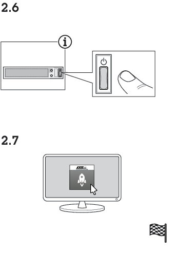
After you have configured Windows®, AXIS Recorder Toolbox is opened automatically and you are guided through the first-time configuration wizard. In this wizard, you can configure several basic and necessary settings before you manage your device in AXIS Recorder Toolbox.
The settings are for the server. To change the switch’s settings, go to the switch’s management page. See Settings.
Change the computer name if you want and click Next.
Under Date and time, configure the following settings and click Next.
Select a time zone.
To set up an NTP server, select NTP server and enter the NTP server address.
To set manually, select Manual and select a date and time.
Under Network settings, configure the following settings and click Next.
Use automatic IP settings (DHCP) and Use automatic DNS settings are turned on by default.
If your device is connected to a network with a DHCP server, the assigned IP address, subnet mask, gateway, and preferred DNS are automatically displayed.
If your device is not connected to a network or there is no DHCP server available, enter the IP address, subnet mask, gateway, and preferred DNS manually depending on the network requirements.
Click Finish. If you have changed the computer name, AXIS Recorder Toolbox will prompt you to restart the device.
Connect to a server
The AXIS Camera Station S22 Appliance Series client lets you connect to a single server or multiple servers in different ways:
- Last used servers
- Connect to the servers used in the previous session.
- This computer
- Connect to the server installed on the same computer as the client.
- Remote server
- See Connect to a remote server.
- The first time you connect to a server, the client checks the server certificate ID. To make sure you're connecting to the correct server, compare the certificate ID with the one displayed in AXIS Camera Station S22 Appliance Series Service Control.
| Server list | To connect to servers from a server list, select a one from the Server list drop-down menu. Click |
| Import server list | To import a server list file exported from AXIS Camera Station, click Import server list and browse to an .msl file. |
| Delete saved passwords | To delete saved usernames and passwords for all connected servers, click Delete saved passwords. |
| Change client proxy settings | If you can't connect to a server, you might need to update your client proxy settings. Click Change client proxy settings. |
Connect to a remote server
Select Remote server.
Select a server from the Remote server drop-down list or enter the IP or DNS address. If the server isn’t listed, click
 to refresh the list of all the available remote servers. If the server is configured to accept clients on a different port than the default port number 55754, enter the IP address followed by the port number, for example, 192.168.0.5:46001.
Do one of the following:
Select Log in as current user to log in as the current Windows® user.
Clear Log in as current user and click Log in. Select Other user and provide another username and password to log in with different credentials.
Sign in to AXIS Secure Remote Access
To improve security and functionality, we’re upgrading Axis Secure Remote Access (v1) to Axis Secure Remote Access v2. We’re discontinuing the current version on December 1st, 2025, and we strongly recommend that you upgrade to Axis Secure Remote Access v2 before that.
What does this mean for your AXIS Camera Station S22 Appliance Series system?
- After December 1st, 2025, you will no longer be able to remotely access your system using Axis Secure Remote Access (v1).
- To use Axis Secure Remote Access v2, you must upgrade to AXIS Camera Station Pro version 6.8. This upgrade is currently free for all AXIS Camera Station 5 users until March 1st, 2026.
- When trying to connect to a server using Axis Secure Remote Access, the server can’t upgrade the client automatically.
- If the proxy server is between the network device and the AXIS Camera Station S22 Appliance Series server, you must configure the proxy settings in Windows on the AXIS Camera Station S22 Appliance Series server to access the server using AXIS Secure Remote Access.
Click the Sign in to AXIS Secure Remote Access link.
Enter your My Axis account credentials.
Click Sign in.
Click Grant.
Configure AXIS Camera Station Pro
Before you start:
Configure your network depending on your installation. See Network configuration.
Configure your server ports if needed. See Server port configuration.
Consider security issues. See Security considerations.
After necessary configurations, you can start to work with AXIS Camera Station Pro:
Start the video management system
Double-click the AXIS Camera Station Pro client icon to start the client. When you start the client for the first time, it attempts to log in to the AXIS Camera Station Pro server installed on the same computer as the client.
You can connect to multiple AXIS Camera Station Pro servers in different ways.
Add devices
The first time you start AXIS Camera Station S22 Appliance Series, the Add devices page opens and searches the network for devices to add.
Select the devices you want to add from the list. If you can’t find a device, click Manual search or type to filter.
Click Add.
Click Close to skip configuration and continue later. To continue with the configuration now:
Choose Quick configuration or Site Designer configuration. See for more information.
Select Add image overlay for date, time, and text to add overlays to any Axis cameras that don’t already have one.
Click Next.
Select your Recording method preference.
Click Next.
Choose your Retention time and Recording storage, and click Finish to apply the configuration.
Configure recording method
Go to Configuration > Recording and events > Recording method.
Select a camera.
Turn on Motion detection, or Continuous, or both.
Click Apply.
View live video
Open a Live view tab.
Select a camera to view its live video.
View recordings
Open a Recordings tab.
Select the camera you want to view recordings from.
Add bookmarks
Go to the recording.
In the timeline, zoom in and out and move the timeline to put the marker at your desired position.
Click
 .
.Enter the bookmark name and description. Use keywords to make the bookmark easy to find.
Select Prevent recording deletion to lock the recording.
- Note
To unlock the recording, clear Prevent recording deletion or delete the bookmark.
Click OK to save the bookmark.
Export recordings
Open a Recordings tab.
Select the camera you want to export recordings from.
Click
 to display the selection markers.
Drag the markers to include the recordings that you want to export.
Click
 to open the Export tab.
Click Export...
Play and verify recordings in AXIS File Player
Go to the folder with the exported recordings.
Double-click AXIS File Player.
Click
 to show the recording’s notes.
To verify the digital signature:
Go to Tools > Verify digital signature.
Select Validate with password and enter your password.
Click Verify to see the verification results.
- Note
- A digital signature is different from signed video. Signed video lets you trace a recording back to the camera it came from, so you can verify it wasn't tampered with. See Signed video and the camera’s user manual for more information.
- If stored files don’t have any connection with an AXIS Camera Station database (non-indexed files), you need to convert them to make them playable in AXIS File Player. Contact Axis Technical support for help converting your files.
Network configuration
Configure proxy or firewall settings before using AXIS Camera Station S22 Appliance Series if the client, server, and connected network devices are on different networks.
Client proxy settings
If a proxy server is between the client and the server, configure the proxy settings in Windows on the client computer. Contact Axis support for more information.
Server proxy settings
If the proxy server is between the network device and the server, you must configure the proxy settings in Windows on the server. Contact Axis support for more information.
NAT and Firewall
When a NAT or firewall separates the client and the server, configure it to ensure that the HTTP port, TCP port, and streaming port specified in AXIS Camera Station S22 Appliance Series Service Control can pass through. Contact your network administrator for help.
Server port configuration
The AXIS Camera Station S22 Appliance Series server uses ports 55752 (HTTP), 55754 (TCP), 55756 (mobile communication), and 55757 (mobile streaming) for communication between the server and the client. You can change the ports in AXIS Camera Station Service Control if required.
Security considerations
To prevent unauthorized access to cameras and recordings:
Use strong passwords for all network devices (cameras, video encoders, and auxiliary devices).
Install the AXIS Camera Station S22 Appliance Series server, cameras, video encoders, and auxiliary devices on a secure network, separate from the office network. You can install the AXIS Camera Station S22 Appliance Series client on a computer on another network, for example, a network with internet access.
Make sure all users have strong passwords.
License a system online
Both the AXIS Camera Station client and the server must have internet connection.
Go to Configuration > Licenses > Management.
Make sure Manage licenses online turns on.
Sign in with your My Axis account.
The license key automatically generates and appears under License keys.
If you purchased license keys separately, enter your license key under Add license key.
Click Add.
In AXIS Camera Station client, make sure your license keys appear under Configuration > Licenses > Keys.
License a system offline
Go to Configuration > Licenses > Management.
Turn off Manage licenses online.
Click Export system file.
Save your system file to a USB flash drive.
Sign in with your My Axis account.
Click Upload system file to upload the system file from your USB flash drive.
The license key automatically generates and shows under License keys.
If you purchased license keys separately, enter your license key under Add license key.
Click Add.
Under License keys, click Download license file and save the file to a USB flash drive.
In AXIS Camera Station client, go to Configuration > Licenses > Management.
Click Import license file and select the license file on your USB flash drive.
Make sure your license keys appear under Configuration > Licenses > Keys.
Manage local Windows® user accounts
Create a user account
To help keep your personal data and information more secure, we recommend that you add a password for each local account.
Once you create a password for a local account, don't forget it. There’s no way to recover a lost password for local accounts.
Go to Settings > Accounts > Other users > Add other user and click Add account.
Click I don’t have this person’s sign-in information.
Click Add a user without a Microsoft account.
Enter a user name, password and password hint.
Click Next and follow the instructions.
Create an administrator account
Go to Settings > Accounts > Other people.
Go to the account you want to change and click Change account type.
Go to Account type and select Administrator.
Click OK.
Restart your device and sign in with the new administrator account.
Create a local user group
Go to Computer Management.
Go to Local Users and Groups > Group.
Right-click Group and select New Group.
Enter a group name and a description.
Add group members:
Click Add.
Click Advanced.
Find the user account(s) you want to add to the group and click OK.
Click OK again.
Click Create.
Delete a user account
When you delete an account you remove the user account from the login screen. You also remove all files, settings and program data stored on the user account.
Go to Settings > Accounts > Other people.
Go to the account you want to remove and click Remove.
Change a user account's password
Log in with an administrator account.
Go to User Accounts > User Accounts > Manage another account in sequence.
You’ll see a list with all user accounts on the device.
Select the user account whose password you would like to change.
Click Change the password.
Enter the new password and click Change password.
Create a password reset disk for a user account
We recommend to create a password reset disk on a USB flash drive. With this, you can reset the password. Without a password reset disk, you can’t reset the password.
If you’re using Windows® 10, or later, you can add security questions to your local account in case you forget your password, so you don't need to create a password reset disk. To do this, got to Start and click Settings > Sign-in options > Update your security questions.
Sign in to your device with a local user account. You can’t create a password reset disk for a connected account.
Plug an empty USB flash drive into your device.
From the Windows® search field, go to Create a password reset disk.
In the Forgotten Password setup assistant, click Next.
Select your USB flash drive and click Next.
Type your current password and click Next.
Follow the onscreen instructions.
Remove the USB flash drive and keep it in a safe placet. You don't have to create a new disk when you change your password even if you change it several times.
Manage AXIS Camera Station Pro user accounts
User permissions
Go to Configuration > Security > User permissions to see the users and groups in AXIS Camera Station S22 Appliance Series.
Administrators of the computer that runs the AXIS Camera Station S22 Appliance Series server are automatically granted administrator privileges in AXIS Camera Station S22 Appliance Series. You can’t change or remove the Administrators group's privileges.
Before you can add a user or group, make sure they’re registered on the local computer or have a Windows® Active Directory user account. To add users or groups, see Add users or groups.
When a user belongs to a group, they receivet the highest role permission assigned to them individually or to the group. For example, a user with access to camera X who also belongs to a group with access to cameras Y and Z has access to all three cameras.
| Indicates the entry is a single user. | |
| Indicates the entry is a group. | |
Name | Username as it appears in the local computer or Active Directory. |
Domain | The domain that the user or group belongs to. |
Role | The access role assigned to the user or group. Possible values: Administrator, Operator, and Viewer. |
Details | Detailed user information as it appears on the local computer or in Active Directory. |
Server | The server that the user or group belongs to. |
Add users or groups
Microsoft Windows® and Active Directory users and groups can access AXIS Camera Station S22 Appliance Series. To add a user to AXIS Camera Station S22 Appliance Series, you must add users or a group to Windows®.
To add a user in Windows® 10 and 11:
Press the Windows key + X and select Computer Management.
In the Computer Management window, navigate to Local Users and Groups > Users.
Right-click Users and select New User.
In the popup dialog, enter the new user’s details and clear User must change password at next login.
Click Create.
If you use an Active Directory domain, consult your network administrator.
Add users or groups
Go to Configuration > Security > User permissions.
Click Add. The available users and groups appear in the list.
Under Scope, select where to search for users and groups.
Under Show, select to show users or groups. The search results may not appear if there are too many users or groups. Use the filter to narrow the results.
Select the users or groups and click Add.
| Scope | |
|---|---|
Server | Select to search for users or groups on the local computer. |
Domain | Select to search for Active Directory users or groups. |
Selected server | When connected to multiple AXIS Camera Station S22 Appliance Series servers, select a server to search for users or groups on that server. |
Configure a user or group
Select a user or group in the list.
Under Role, select Administrator, Operator, or Viewer.
If you selected Operator or Viewer, you can configure the user or group privileges. See User or group privileges.
Click Save.
Remove a user or group
Select the user or group.
Click Remove.
In the pop-up dialog, click OK to remove the user or group.
User or group privileges
There are three roles you can assign to a user or group. For how to define the role for a user or group, see Add users or groups.
- Administrator
- Full access to the entire system, including access to live and recorded video of all cameras, all I/O ports, and views. This role is required to access system configuration.
- Operator
- Select cameras, views, and I/O ports to get access to live and recorded video. An operator has full access to all functionality of AXIS Camera Station S22 Appliance Series except system configuration.
- Viewer
- Access to live video of selected cameras, I/O ports, and views. A viewer doesn’t have access to recorded video or system configuration.
Cameras
The following access privileges are available for users or groups with the Operator or Viewer role.
Access | Allow access to the camera and all camera features. |
Video | Allow access to live video from the camera. |
Audio listen | Allow access to listen from the camera. |
Audio speak | Allow access to speak to the camera. |
Manual Recording | Allow starting and stopping recordings manually. |
Mechanical PTZ | Allow access to mechanical PTZ controls. Available only for cameras with mechanical PTZ. |
PTZ priority | Set the PTZ priority. A lower number means a higher priority. No assigned priority is set to |
Views
The following access privileges are available for users or groups with the Operator or Viewer role. You can select multiple views and set the access privileges.
Access | Allow access to the views in AXIS Camera Station S22 Appliance Series. |
Edit | Allows editing of views in AXIS Camera Station S22 Appliance Series. |
I/O
The following access privileges are available for users or groups with the Operator or Viewer role.
Access | Allow full access to the I/O port. |
Read | Allows viewing the state of the I/O port without changing it. |
Write | Allows changing the state of the I/O port. |
System
You can’t configure grayed-out access privileges in the list. A check mark means the user or group has this privilege by default.
The following access privileges are available for users or groups with the Operator role. Take snapshots is also available for the Viewer role.
Take snapshots | Allows taking snapshots in live view and recording mode. |
Export recordings | Allow exporting recordings. |
Generate incident report | Allow generating incident reports. |
Prevent access to recordings older than | Prevent access to recordings older than the specified number of minutes. Users can’t find these recordings when they search. |
Access alarms, tasks, and logs | Get alarm notifications and allow access to the Alarms and tasks bar and Logs tab. |
Access data search | Allow searching for data to track what happened at the time of an event. |
Add categories to events | Allow adding categories to events in the Recordings tab. |
Remove categories from event | Allow removing categories from events in the Recordings tab. |
Access control
The following access privileges are available for users or groups with the Operator role. Access Management is also available for the Viewer role.
Access control configuration | Allow configuration of doors and zones, identification profiles, card formats, and PIN, encrypted communication, and multi-server. |
Access management | Allow access management and access to the Active Directory settings. |
The following access privileges are available for users or groups with the Viewer role.
System health monitoring
The following access privileges are available for users or groups with the Operator role. Access to system health monitoring is also available for the Viewer role.
Configuration of system health monitoring | Allows configuration of system health monitoring. |
Access to system health monitoring | Allows access to system health monitoring. |
Manage your device
Update Windows®
Windows® periodically checks for updates. When an update is available, your device automatically downloads the update but you've to install it manually.
Recording will be interrupted during a scheduled system restart.
To manually check for updates:
Go to Settings > Windows Update.
Click Check for updates.
Configure Windows® update settings
It is possible to change how and when Windows® do its updates to suit your needs.
All ongoing recordings stop during a scheduled system restart.
Open the Run app.
Go to Windows System > Run, or
Type
gpedit.mscand click OK. The Local Group Policy Editor opens.Go to Computer Configuration > Administrative Templates > Windows Components > Windows Update.
Configure the settings as required, see example.
Example
To automatically download and install updates without any user interaction and have the device restart, if necessary, at out of office hours, use the following configuration:
Open Always automatically restart at the scheduled time and select:
Enabled
The restart timer will give users this much time to save their work (minutes): 15.
Click OK.
Open Configure Automatic Updates and select:
Enabled
Configure Automatic updates: Auto download and schedule the install
Schedule Install day: Every Sunday
Schedule Install time: 00:00
Click OK.
Open Allow Automatic Updates immediate installation and select:
Enabled
Click OK.
Reset your server
You can use the server reset button to reset your server. It will take more than one hour to reset your server.
Power off your device.
Press and hold the server reset button for 5 seconds. Windows® RE will be started.
Select Troubleshoot.
Select Reset your PC.
Select Keep my files or Remove everything. If you select Keep my files, you need to provide the administrator credentials.
Follow the instructions on the screen.
The server reboots and starts the procedure to restore Windows® to factory default settings.
Reset your switch
You can reset your switch to factory default settings by using one of the following ways:
The switch reset button. Before you start, ensure that the switch is on. Press and hold the switch reset button for about 5 seconds until the power button LED at the rear side of the device turns blue. It will take about 6 minutes.
The switch’s management page. See Reset to factory default settings.
Add additional storage
The demand for storage can differ. Retention time of stored data or for storing high-resolution recordings often results in a need to install more storage. This section explains how to install an additional hard drive in your AXIS S22 series product.
Follow the instructions below to add additional storage to applicable AXIS S22 products. These instructions are as-is, and Axis Communications AB takes no responsibility for loss of data or misconfiguration during these steps. The standard precautions should be taken to backup data that is business critical. The following procedure of expanding storage will not be supported by Axis Technical Support.
To avoid electrostatic discharge, we recommend that you always use a static mat and static strap while working on internal system components.
Warranty
Detailed information about warranty is available at: www.axis.com/support/warranty.
Manage the built-in switch
About the built-in switch
The AXIS Camera Station S22 Appliance Series comes with an integrated Power over Ethernet (PoE) switch. You can configure and manage the built-in switch.
The purpose of the switch is to segregate traffic on the network so that security cameras and related traffic managed by the switch (PoE ports and U1 network uplinks) are not shared with other networks.
- The switch’s power management follow these rules:
Each port can reserve power according to the connected powered device’s PoE class. Power can also be allocated manually and by actual consumption.
If the actual power consumption for a given port exceeds the reserved power for that port, it will shut down.
Ports will shut down when the actual power consumption for all ports exceeds the total amount of power that the power supply can deliver. The ports are then shut down according to the ports priority where a lower port number means higher priority.
Select a language
In the switch’s management page, go to ![]() > Language and select the language that you want to use.
> Language and select the language that you want to use.
Go to the help pages
In the switch’s management page, go to ![]() > Help.
> Help.
Log in to the switch's management page
Go to the switch’s management page.
From the web browser, enter the switch’s IP address. By default: 192.168.0.1
From AXIS Recorder Toolbox, go to Switch > Open the switch configuration.
From AXIS Camera Station Client, go to Configuration > Switch > Management. See Configure switch.
Log in with your credentials.
user name:
adminpassword: you can find the randomly generated password on a sticker underneath the product or a self-adhesive sticker in the box content.
To log out the switch's management page, go to ![]() > Log out.
> Log out.
Overview
In the switch’s management page, click Overview.
General information
| Category | Item | Description |
| Ports summary | Active ports | The number of ports that are in use. |
| Ports using PoE | The number of ports with PoE enabled that are in use. | |
| Locked ports | The number of ports that are locked. | |
| Current PoE usage | The total power in watts and percentage consumed by the PoE devices. | |
| Port status | Click the port to see the details about the port. | |
| Active | The port is in use. | |
| Inactive | The port is ready to be used. | |
| Blocked | The port is blocked. |
Port list
| Item | Description |
| Port | The port number that the device is connected to. |
| Device | The name of the device connected to the port. |
| IP address | The IP address of the device connected to the port. |
| PoE | Displays the PoE status. You can click the icon to turn on or turn off PoE on the port. |
| Power consumption (W) | The power in watts consumed by the device connected to the port. |
| Upstream (Mbit/s) | The average data rate in megabits per second for outbound data on the port. |
| Downstream (Mbit/s) | The average data rate in megabits per second for inbound data on the port. |
| MAC address | The MAC address of the device connected to the port. |
| Lock | Displays whether the port is locked. You can click the icon to lock or unlock the port. |
Turn on and turn off PoE
Turn on PoE on a port
In the switch’s management page, click Overview.
In the PoE column, click
 to turn on PoE on the specific port.
Turn on PoE on all ports
In the switch’s management page, click Overview.
Click
 and select Turn on PoE on all ports.
Turn off PoE on a port
In the switch’s management page, click Overview.
In the PoE column, click
 to turn off PoE on the specific port.
Turn off PoE on all ports
In the switch’s management page, click Overview.
Click
and select Turn off PoE on all ports.
You can also turn on and turn off PoE in the Power management page.
Lock and unlock ports
You can lock a MAC address to a port so that only traffic coming from that MAC address will pass. This improves security and prevents unauthorized users from connecting a laptop or other devices to the security network.
Lock a port
In the switch’s management page, click Overview.
In the Lock column, click
to lock the port.
Lock all ports
In the switch’s management page, click Overview.
Click
and select Lock all ports.
Unlock a port
In the switch’s management page, click Overview.
In the Lock column, click
to unlock the port.
Unlock all ports
In the switch’s management page, click Overview.
Click
and select Unlock all ports.
Power management
In the switch’s management page, click Power management.
General information
Ports using PoE: the number of ports with PoE enabled that are in use.
Current PoE usage: the PoE power in watts consumed by devices and the percentage of used PoE power out of the total dedicated PoE power.
Power requested: the total power in watts and percentage allocated to devices. Only available when you select Reserved power as the power allocation method.
Port list
| Item | Description |
| Port | The port number that the device is connected to. |
| PoE | The PoE status. You can click the icon to turn on or turn off PoE on the port. |
| PoE class | The PoE class of the connected device. |
| Priority | The priority of power allocation to the connected device. Lower numbered ports have higher priority. By default, the priority is the port number. |
| Power consumption (W) | The power in watts consumed by the device connected to the port. |
| Power requested (W) | The power in watts requested by the device connected to the port. Only available when you select Reserved power as the power allocation method. |
| Power allocated (W) | Manually adjust the power allocated to the port. Only available when you select Reserved power > Manual as the power allocation method. |
Allocate power
PoE power can be allocated to the connected devices in the following ways:
Reserved power: In this method, each port reserves the amount of power. The total reserved power cannot exceed the total power budget. A port will not be powered up if the device tries to reserve more power than available. This method ensures that the connected devices will be powered.
PoE class: Each port automatically determines the amount of power to reserve according to the PoE class of the connected device.
Manual: You can manually adjust the amount of power allocated to each port by changing the value under Power allocated.
LLDP-MED: Each port determines the amount of power to reserve by exchanging PoE information using the LLDP protocol.
- Note
The power allocation method LLDP-MED works only for cameras with firmware 9.20 or later.
Actual consumption: In this method, devices use the amount of power they need until reaching the power budget. A port will be shut down if the device consumes more power than available. The ports are shut down according to the priority.
To change the power allocation method:
In the switch’s power management page, go to Power management.
To use the reserved power method, select Reserved power under Allocate power and select PoE Class, Manual, or LLDP-MED under Reserved power determined by.
To use the actual consumption method, select Actual consumption under Allocate power.
If you have selected Manual, go to the Power allocated column and change the power allocated to the connected device.
If you want to change the priority of the connected device, select a priority for that device. The priority of other devices will change automatically.
Example
In this example, the switch has a total power budget of 135 W. A PoE class 4 device requests 30 W power and actually consumes 15 W power. A PoE class 2 device requests 7 W power and actually consumes 5 W power.
Allocate power by PoE class
Each port reserves the amount of power according to the device’s PoE class.
The switch can power 4 PoE class 4 devices and 2 PoE class 2 devices.
The total power reserved is (4 x 30) + (2 x 7) =134 W.
The actual power consumed is (4 x 15) + (2 x 5) = 70 W.
In this way, all connected devices are guaranteed enough power and the priority is less important.
Allocate power manually
The reserved power is manually adjusted to 20 W for PoE class 4 devices.
The switch can power 5 PoE class 4 devices and 3 PoE class 2 devices.
The total power reserved is (5 x 20) + (3 x 7) = 121 W.
The actual power consumed is (5 x 15) + (3 x 5) = 90 W.
In this way, all connected devices are guaranteed enough power and the priority is less important.
Allocate power by actual consumption
When connecting a device, the switch will power it up if the max power limit can be ensured at that time.
First the switch connects to five PoE class 4 devices and the actual consumption of power is 5 x 15 = 75 W.
Later each device consumes up to 30 W power. The switch cannot power five devices and the port 5 with the lowest priority is shut down. The actual consumption is 4 x 30 = 120 W.
In this way, the priority of the port is important. The port with the lowest priority will be shut down first when the actual consumption exceeds the power budget.
Settings
Configure network settings
You can change the switch’s IP address. But for most camera installations, we recommend using the default settings. The reason for this is that a surveillance network is normally isolated from other networks, for example a corporate LAN. In this case, you would only use the surveillance network to manage and collect surveillance devices and data from the video management software installed on the server.
In the switch’s management page, go to Settings > Network settings.
Enter the connection type, IP address, subnet mask, gateway, DNS1, DNS2, and hostname.
- Note
The factory default settings are: a static IP connection with address 192.168.0.1 and a subnet mask with address 255.255.255.0.
Click Save.
Configure date and time
In the switch’s management page, go to Settings > Date and time.
Select the country and time zone.
To set the time manually, select Manual and manually adjust the time.
To set up an NTP server, select NTP server and enter the NTP server address.
- Note
NTP only works when the switch is connected to a network and configured with Internet access.
Click Save.
Configure DHCP server
If the switch’s DHCP server is enabled and your AXIS Camera Station S22 Appliance is connected to an external network with its own DHCP server, you will have IP address conflicts. This might result in the corporate network not working.
You can configure the switch to use its internal DHCP server for assigning IP addresses to connected devices. When you use the switch uplink connection to allow devices to access or being accessed by external application, you must specify the gateway and DNS addresses.
In the switch’s management page, go to Settings > DHCP server.
Select Use DHCP server.
Enter the start IP address, end IP address, subnet mask, gateway, DNS 1, DNS 2, lease length, and domain name.
Click Save.
Configure SNMP
In the switch’s management page, go to Settings > SNMP.
Enter the server name, contact, and location used for the SNMP connection.
If you want to use SNMPV1 or SNMPV2c, select SNMPV1 / SNMPV2c and enter the read community.
If you want to use SNMPV3, select SNMPV3 (MD5) and enter the username and password.
- Note
Currently we only support MD5 authentication used for SNMP.
Click Save.
Configure web settings
In the switch’s management page, go to Settings > Web settings.
Enter the port number.
For more secure connection, select Secure connection (HTTPS) and enter the port number used for HTTPS connection.
Click Save.
If you have changed the port number, ensure you record the new port number. If you’ve forgotten the new port number, contact Axis support.
Maintenance
Update firmware
In the switch’s management page, go to Maintenance > Update firmware.
Drag and drop the firmware file or click Browse and navigate to the firmware file.
Click Upload.
After the firmware updating is done, reboot the switch.
Reboot the switch
While the switch reboots, all connected devices will temporarily lose connection with the switch including PoE.
In the switch’s management page, go to Maintenance > Reboot switch.
Click Reboot and Yes.
When the switch reboots after a few minutes, enter your username and password to log in.
Backup the switch's settings
The username and password are included in the backup file.
In the switch’s management page, go to Maintenance > Backup and restore.
Click Create a backup file. The backup file in the .bin format is created in the Downloads folder.
Restore the switch's settings
To restore the switch’s settings, you must previously have created a backup file.
In the switch’s management page, go to Maintenance > Backup and restore.
Drag and drop the backup file or click Browse and navigate to the backup file.
Click Upload.
It could take a few minutes to restore the switch from the backup file. Once the settings are restored, the switch will automatically reboot and you need to log in again.
Manage certificates
In the switch’s management page, go to Maintenance > Manage certificates.
Click
 and navigate to your private key file.
Click
and navigate to your certificate file.Click
and navigate to your CA bundle file.Click Save.
Reboot the switch.
Change password
You can change the switch's default password to a password you choose yourself.
Ensure you select a password you remember. If you have forgotten the new password, contact Axis support.
In the switch’s management page, go to Maintenance > Change password.
Enter the current password and your new password as required.
Click Save.
Reset to factory default settings
In the switch’s management page, go to Maintenance > Reset to factory default settings.
Click Reset and Yes.
After the reset is done, the switch will reboot automatically.
Log
In the switch’s management page, click Log to see a list of logs. Click Refresh to refresh the list. Click the column title to sort in alphabetical order.
| Item | Description |
| Time | The date and time when the log event happened. |
| Level | The serious level shown as warning icons. |
| User | The user that initiates the log event. |
| IP address | The IP address of the user that initiates the log event. |
| Service | The service that the log event is related to. Possible values are desktop, network, system, ntpd, storage, dhcp, etc. |
| Event | The description about the log event. |
Create switch reports
In the switch’s management page, click Log.
Click Create switch report.
Product overview
Front side
- Audio in
- Audio out
- System power LED
- Disk activity LED
- Status LEDs of PoE ports
- USB 3.0
Rear side
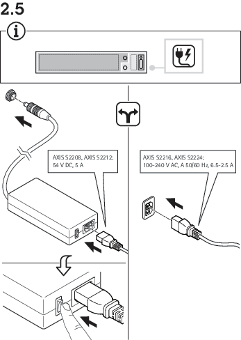
- Power connector
- PoE ports
- SFP switch uplink (U1)
- RJ45 switch uplink (U1)
- Switch reset button
- Server reset button
- USB 2.0 x2
- RJ45 server uplink (U2)
- HDMI port
- Displayport
- Power button
Specifications
Front LEDs
| LED indicator | Color | Indication |
| Power | Green | Server on |
| Network ports | Green | Link state |
| Hard drive | Blinks amber | Hard drive activity |
| Blinks red | Possible hard drive failure |
Rear LEDs
| Network speed and activity | Color | Indication |
| Right LED | Amber | 10/100 Mbit/s |
| Green | 1000 Mbit/s | |
| Left LED | Blinks green | Network activity |
| Power button | Color | Indication |
| When the power button is not pressed | Off | Switch and server off |
| Blue | During switch boot | |
| Green | Switch boot completed | |
| When the power button is pressed | Red (flashes once for 1s) | Power on |
| >5s blinks green | Restarting server | |
| >10s steady blue | Power off switch | |
| >15s blinks blue | Power off switch and server |
Troubleshooting
Perform a system recovery
If the device has had a complete system failure, you must use a recovery image to recreate the Windows® system. To download the AXIS Network Video Recorder Recovery Kit, contact Axis technical support and supply the serial number of your device.
The AXIS Network Video Recorder Recovery Kit comes in two variants:
- sb11 — for devices still using the 2011 certificate.
- sb23 — for devices that have moved to the 2023 certificate.
Check your certificate status before you download the Recovery Kit, and select the matching variant. If you select the wrong variant, the installation won't produce a bootable result, and you'll need to start over with the correct image. This won't damage your device.
If your device already has the 2023 certificate installed, the sb11 variant is still safe to use, as long as the 2011 certificate hasn't been manually revoked. Once it's revoked, only sb23 will work.
- To recreate the system:
Download the AXIS Network Video Recorder Recovery Kit and AXIS Network Video Recorder Recovery: ISO to USB Tool.
Insert a USB drive into your computer.
Use a USB drive with a minimum of 16 GB.
The USB drive will be formatted, and all existing data will be erased.
Run the AXIS Network Video Recorder Recovery: ISO to USB Tool and follow the onscreen instructions.
Writing data to the USB drive takes approximately 10 to 15 min. Don’t remove the USB drive until the process is complete.
After the AXIS Network Video Recorder Recovery: ISO to USB Tool is complete, take the USB drive and plug it into your device.
Start your device.
When you see the Axis splash screen, press F12.
Click UEFI: USB Drive.
Navigate to your USB drive and press enter. The system boots into the AXIS Network Video Recorder Recovery Kit.
Click Reinstall Operating System.
The recovery takes roughly 10 to 15 min to complete. You find detailed instructions in the download for the recovery kit.
Troubleshoot AXIS Camera Station Pro
For information about how to troubleshoot AXIS Camera Station Pro, go to the AXIS Camera Station Pro user manual.
Need more help?
Useful links
Contact support
If you need more help, go to axis.com/support.