Features and settings
This is an overview of all features and settings available in the web interface of devices with AXIS OS.
No single device contains all settings listed here.
To reach the device’s web interface, type the device’s IP address in a web browser. For more information, see AXIS OS Knowledge base or the user manual for your device at help.axis.com.
Show or hide the main menu. Access the release notes. Access the product help. Change the language. Set light theme or dark theme. The user menu contains:
The context menu contains:
|
Status
Audio system info
This information is only shown for devices that belong to an AXIS Audio Manager Edge site.
AXIS Audio Manager Edge: Launch AXIS Audio Manager Edge. |
AXIS Image Health Analytics
Shows the status of the preinstalled application AXIS Image Health Analytics and if the application has detected any issues.
Go to apps: Go to the Apps page where you can manage your installed applications. Open application: Open AXIS Image Health Analytics in a new browser tab. |
Configuration
Shows the setup assistant configurations, including installation type, lens selection, installation focus, PTZ information.
Start setup assistant: Configure the setup assistant. View setup assistant: View and update the setup assistant. |
Connected clients
Shows the number of connections and connected clients.
View details: View and update the list of connected clients. The list shows IP address, protocol, port, state, and PID/process of each connection. |
Device info
Shows information about the device, including AXIS OS version and serial number.
Upgrade AXIS OS: Upgrade the software on your device. Takes you to the Maintenance page where you can do the upgrade. |
Door connection
Door: Shows the status of connected doors. |
Locate device
Shows the locate device information, including serial number and IP address.
Locate device: Plays a sound that helps you identify the speaker. For some products, the device will flash a LED. |
Network ports
Shows the status of network ports and power information including allocated power and total PoE consumption.
Network ports settings: Click to go to the Network ports page where you can change the settings. |
Ongoing recordings
Shows ongoing recordings and their designated storage space.
Recordings: View ongoing and filtered recordings and their source. For more information, see Recordings Shows the storage space where the recording is saved. |
Power status
Shows power status information, including current power, average power, and max power.
Power settings: View and update the power settings for the device. Takes you to the Power settings page where you can change the power settings. |
PTZ
Shows the PTZ status and the time of the last test.
Test: Start a test of the PTZ mechanics. During the test, there are no video streams available. When the test is finished, the device restores to its home position. |
Security
Shows what kind of access to the device that is active, what encryption protocols are in use, and if unsigned apps are allowed. Recommendations to the settings are based on the AXIS OS Hardening Guide.
Hardening guide: Link to AXIS OS Hardening guide where you can learn more about cybersecurity on Axis devices and best practices. |
Speaker test
Shows whether the speaker has been calibrated or not.
Speaker test: Calibrate the speaker. Takes you to the Speaker test page where you can do the calibration and run the speaker test. |
Storage
Shows the storage status and information including free space and disk temperature.
Storage settings: Click to go to the Onboard storage page where you can change the settings. |
Time sync status
Shows NTP synchronization information, including if the device is in sync with an NTP server and the time remaining until the next sync, as well as the PTP status.
NTP settings: View and update the NTP settings. Takes you to the Time and location page where you can change the NTP settings. |
Video input
Shows video input information, including if video input is configured and detailed information for each channel.
Video input settings: Update the video input settings. Takes you to the Video input page where you can change the video input settings. |
Sequences
Monitor
Shows information about the sequence. |
USB
To activate USB functionality, turn on USB ports in System > Accessories and restart the device.
Allow USB input: Turn on to let the device use the USB input. Invert joystick axes: Select if you want to invert the joystick axes:
Always play audio when a single segment is selected: Turn on to play audio when a single segment is selected. |
Sequences
To avoid problems with multi-stream playbacks, follow the recommendations in the web interface.
Add sequence: Click to add a sequence. Name: Enter a name for the sequence. : Click to select how many sources you want to display. : Click to add one more . : Click to play the sequence. The context menu contains: Edit sequence Delete sequence Set as default sequence |
Fallback
Add fallback image: Click to add an image that can be displayed if the camera stream is lost. |
Device
I/Os and relays
Input
Output.
I/O:
|
Relays
|
Alarms
Device motion: Turn on to trigger an alarm in your system when it detects a movement of the device. Casing open: Turn on to trigger an alarm in your system when it detects an open door controller case. Turn off this setting for barebone door controllers. External tamper: Turn on to trigger an alarm in your system when it detects an external tamper. For example, when someone opens or closes the external cabinet.
|
Power monitoring
Main unit
Connected devices: Shows the status, name, address, and the power usage of the connected devices including power usage of all relays, all RS485, and all AUX. |
Peripherals
Readers
Add: Click to add a reader.
Edit: Select a reader and click Edit to make changes for the selected reader. Delete: Select the readers and click Delete to delete the selected readers. |
Wireless locks
You can connect up to 16 ASSA ABLOY Aperio wireless locks using the AH30 Communication Hub. A license is required for the wireless lock.
You must install the AH30 Communication Hub on the secure side.
Connect communication hub: Click to connect the wireless locks. |
Expansion I/O module
You can connect up to 16 AXIS A9910 to one AXIS A9210 to support 128 I/Os, 64 relays and 64 Modbus sensors. The max distance from AXIS A9210 to the last AXIS A9910 is 1000 m.
Add encryption key: Click to set up an encryption key to ensure encrypted communication. Add: Click to add an expansion module.
Edit: Select an expansion module and click to edit. Select an I/O port and click Edit:
Select a relay and click Edit:
Upgrade: Click to upgrade the expansion module software. You can choose to upgrade to the version bundled with the door controller or upload a version of your choice.
|
Sensors
Shows an overview of your connected sensors to AXIS A9210. You can connect up to 8 Modbus sensors directly on the RS485 port, or extend to 16 AXIS A9910 to have 64 Modbus sensors on a single AXIS A9210.
Add: Click to add a sensor.
|
|
Upgrade
Upgrade readers: Click to upgrade the reader’s software. You can only upgrade supported readers when they are online. Upgrade converters: Click to upgrade the converter’s software. You can only upgrade supported converters when they are online. |
Advanced
Door override
It takes direct control of the door relays and overrides the relay configuration in AXIS Camera Station. Only turn on this setting if Axis support has instructed you to do so.
I understand: Click to make it possible to turn on door override. Door override: Click to turn on door override. Door relays: Click Lock, Unlock, or Access to lock the door, unlock the door, or grant access. Available relays: Click Activate or Deactivate to activate or deactivate the relay. |
Video
Click-and-drag to pan and tilt in the live view. Zoom Use the slider to zoom in and out. Focus Use this setting to set focus in the shown area. Depending on the device, different focus modes are available.
Brightness Use this setting to adjust the light intensity in the image, for example, to make objects easier to see. Brightness is applied after image capture, and does not affect the information in the image. To get more details in a dark area, it is sometimes better to try to increase gain or increase exposure time. |
Click to play the live video stream. Click to freeze the live video stream. Click to take a snapshot of the live video stream. The file is saved in the ‘Downloads’ folder on your computer. The image file name is [snapshot_YYYY_MM_DD_HH_MM_SS.jpg]. The size of the snapshot depends on the compression that the specific web-browser engine where the snapshot is received applies, therefore, the snapshot size may vary from the actual compression setting that is configured in the device. Click to show I/O output ports. Use the switch to open or close the circuit of a port, for example, to test external devices. Click to manually turn on or turn off the IR illumination. Click to manually turn on or turn off the white light. Click to access onscreen controls. Enable groups of onscreen controls to make the settings in each group available when users right-click the live stream in the video management software.
Starts the washer. When the sequence starts, the camera moves to the configured position to receive the wash spray. When the whole wash sequence is completed, the camera returns to its previous position. This icon is only visible when the washer is connected and configured. Starts the wiper. Click and select a preset position to go to that preset position in the live view. Or, click Setup to go to the preset position page. Adds or removes a focus recall area. When you add a focus recall area, the camera saves the focus settings at that specific pan/tilt range. When you have set a focus recall area and the camera enters that area in the live view, the camera recalls the previously saved focus. It’s enough to cover half of the area for the camera to recall the focus. Click to select a guard tour, then click Start to play the guard tour. Or, click Setup to go to the guard tours page. Click to manually turn on the heater for a selected period of time. Click to start a continuous recording of the live video stream. Click again to stop the recording. If a recording is ongoing, it will resume automatically after a reboot. Click to show the storage that is configured for the device. To configure the storage, you need to be logged in as an administrator. Click to access autotracking settings. More settings are available if you click the icon from Analytics > Autotracking. Click to access more settings:
Click to show the live view at full resolution. If the full resolution is larger than your screen size, use the smaller image to navigate in the image. Click to show the live video stream in expanded full screen. Click again to exit the expanded full screen mode. Click to show the live video stream in full screen. Press Esc to exit full screen mode. |
Installation
Camera: Select the sensor you want to view in the drop-down menu. The number after Camera indicates the individual sensors. Group view: Select to show all sensors next to each other. Quad view: Select to show all sensors next to each other. |
Capture mode: A capture mode is a preset configuration that defines how the camera captures images. When you change the capture mode, it can affect many other settings, such as view areas and privacy masks. Mounting position: The orientation of the image can change depending on how you mount the camera. Power line frequency: To minimize image flicker, select the frequency your region uses. The American regions usually use 60 Hz. The rest of the world mostly uses 50 Hz. If you're not sure of your region's power line frequency, check with the local authorities. |
Rotate: Select the preferred image orientation. |
Leveling assistant
Overlay: Turn on to add an overlay to assist you when you want to level the image. Buzzer: Turn on to hear the buzzer when you want to level the image. |
P-Iris lens: Select the installed and supported lens. Restart the camera for the changes to take effect. |
Pan: Use the slider to adjust the pan angle. Tilt: Use the slider to adjust the tilt angle. Troubleshoot: Click to get to Reset pan and tilt. |
Close-up reach: Click to show the close-up reach areas. |
Zoom: Use the slider to adjust the zoom level. Autofocus after zooming: Turn on to enable autofocus after zooming. Focus: Use the slider to manually set the focus. Autofocus: Click to make the camera focus on the selected area. If you don’t select an autofocus area, the camera focuses on the entire scene. Autofocus area: Click to show the autofocus area. This area should include the area of interest. Reset focus: Click to make the focus return to its original position. Note In cold environments, it can take several minutes for the zoom and focus to become available. |
Roll: Use the slider to adjust the angle to make the image horizontal. |
Preset Position: A preset position is a saved position you can use to quickly move the camera view to a set position. With a preset position, you can save pan, tilt, roll, zoom, and focus positions. You can use the saved preset positions in the live view. Add new preset: Create a new preset position. You can add up to five PTRZ preset positions.
: Click to delete a preset position. Load selected preset: Select a preset position and click to move the camera to the preset position. |
| Spot focus: Use to set the focus to a fixed area in the center of the image. |
Image correction
Important We recommend you not to use multiple image correction features at the same time, since it can lead to performance issues. Barrel distortion correction (BDC): Turn on to get a straighter image if it suffers from barrel distortion. Barrel distortion is a lens effect that makes the image appear curved and bent outwards. The condition is seen more clearly when the image is zoomed out. Crop: Use the slider to adjust the correction level. A lower level means that the image width is kept at the expense of image height and resolution. A higher level means that image height and resolution are kept at the expense of image width. Remove distortion: Use the slider to adjust the correction level. Pucker means that the image width is kept at the expense of image height and resolution. Bloat means that image height and resolution are kept at the expense of image width. Image stabilization: Turn on to get a smoother and steadier image with less blur. We recommend that you use image stabilization in environments where the device is mounted in an exposed location and subject to vibrations due to, for example, wind or passing traffic. Focal length: Use the slider to adjust the focal length. A higher value leads to higher magnification and a narrower angle of view, while a lower value leads to a lower magnification and a wider angle of view. Stabilizer margin: Use the slider to adjust the size of the stabilizer margin, which determines the level of vibration to stabilize. If the product is mounted in an environment with a lot of vibration, move the slider towards Max. As a result, a smaller scene is captured. If the environment has less vibration, move the slider towards Min. Focus breathing correction: Turn on to keep the angle of view constant while you change the focus. You might not be able to zoom in as much with this function activated. Straighten image: Turn on and use the slider to straighten the image horizontally by rotating and cropping it digitally. The functionality is useful when it’s not possible to mount the camera exactly level. Ideally, straighten the image during installation. : Click to show a supporting grid in the image. : Click to hide the grid. 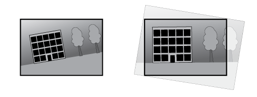 |
Horizon straightening
Horizon straightening compensates for any tilt of the camera, which would otherwise bend the horizon. It provides an image that is perceived to be straight and aligned with the horizon. Horizon position: Use the slider to move the yellow center line to the position of the horizon. You can also move the center line directly in the live view image. Stretch: Turn on to stretch the image in order to fit the whole window. |
Zoom synchronization
Shows whether zoom synchronization between visual and thermal channels is turned on or turned off. |
Traffic camera installation assistance
Traffic camera installation assistance is a tool you can use to get camera setting recommendations based on your specific installation environment.
Surveillance mode Select a surveillance mode to define the primary purpose of your traffic camera:
Capture settings Provide the following information to get accurate recommendations for your camera settings:
Installation overview Displays a visual representation of your camera's position and angle, indicating if any adjustments are needed.
Image settings Shows you the recommended image settings for optimal performance. Apply the recommended settings by leaving the boxes checked. To keep your current settings, uncheck the boxes.
Apply settings: Click to update your camera's settings with the selected values. Once the new settings are applied, review the camera's direction and adjust it if needed. |
Fusion alignment
Fusion opacity
Image order: Select which image appears on top when the thermal and visual image are combined. Image opacity: Drag the slider or enter a percentage to adjust how transparent the top layer appears. |
Align fusion view
Fine tune alignment: Use the arrow buttons to shift the images in small increments until they align. Factory reset: Resets the alignment to factory settings. |
Image
Appearance
Scene profile: Select a scene profile that suits your surveillance scenario. A scene profile optimizes image settings, including color level, brightness, sharpness, contrast, and local contrast, for a specific environment or purpose.
Saturation: Use the slider to adjust the color intensity. You can, for example, get a grayscale image.  Contrast: Use the slider to adjust the difference between light and dark.  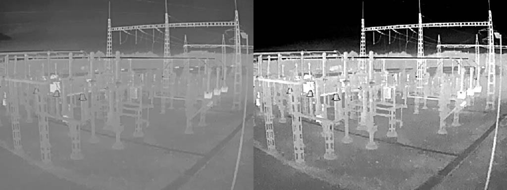 Brightness: Use the slider to adjust the light intensity. This can make objects easier to see. Brightness is applied after image capture, and doesn’t affect the information in the image. To get more details from a dark area, it’s usually better to increase gain or exposure time.  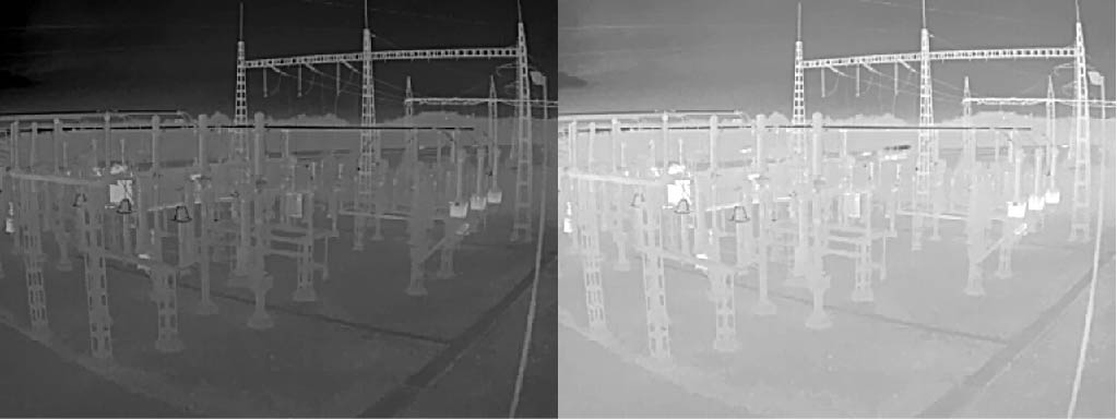 Sharpness: Use the slider to make objects in the image appear sharper by adjusting the edge contrast. If you increase the sharpness, it may increase the bitrate and the amount of storage space needed as well.  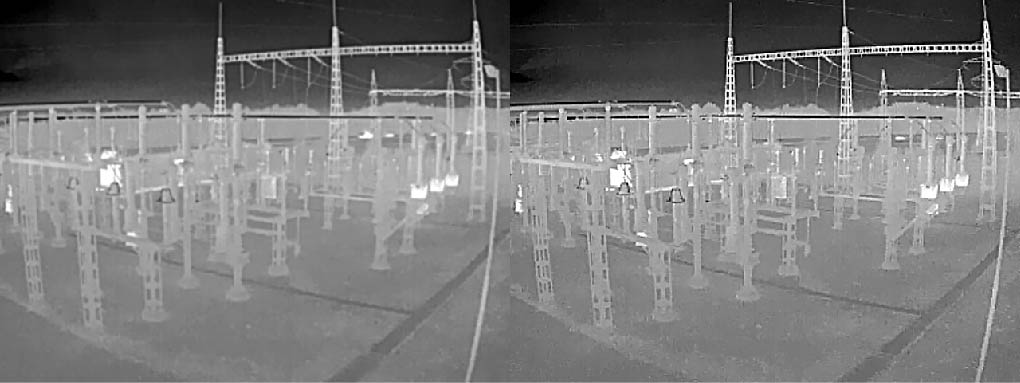 |
Wide dynamic range
WDR: Turn on to make both bright and dark areas of the image visible. Local contrast: Use the slider to adjust the contrast of the image. A higher value makes the contrast higher between dark and light areas. Tone mapping: Use the slider to adjust the amount of tone mapping that is applied to the image. If the value is set to zero, only the standard gamma correction is applied, while a higher value increases the visibility of the darkest and brightest parts in the image. |
White balance
When the camera detects the color temperature of the incoming light, it can adjust the image to make the colors look more natural. If this is not sufficient, you can select a suitable light source from the list.
The automatic white balance setting reduces the risk of color flicker by adapting to changes gradually. If the lighting changes, or when the camera is first started, it can take up to 30 seconds to adapt to the new light source. If there is more than one type of light source in a scene, that is, they differ in color temperature, the dominating light source acts as a reference for the automatic white balance algorithm. This behavior can be overridden by choosing a fixed white balance setting that matches the light source you want to use as a reference.
Light environment:
|
Day-night mode
IR-cut filter:
IR pass filter: Turn on to block visible light and only allow near infrared light to pass through. This toggle button is only available when the IR-cut filter is set to Off. Threshold: Use the slider to adjust the light threshold where the camera changes from day mode to night mode.
Day-to-night delay: Set a delay time to reduce unintended switching from day-to-night mode due to short light changes. For example, flickering lights in a hallway. Night-to-day delay: Set a delay time to reduce unintended switching from night-to-day mode due to short light changes. For example, lights from a car driving by. IR light If your device doesn’t have built-in illumination, these controls are only available when you connect a supported Axis illuminator. Allow illumination: Turn on to let the camera use the built-in light in night mode. Synchronize illumination: Turn on to automatically synchronize the illumination with the surrounding light. The synchronization between day and night only works if the IR-cut filter is set to Auto or Off. Automatic illumination angle: Turn on to use the automatic illumination angle. Turn off to set the illumination angle manually. Illumination angle: Use the slider to manually set the illumination angle, for example, if the angle needs to be different from the camera’s angle of view. If the camera has a wide angle of view, you can set the illumination angle to a narrower angle, which equals a greater tele position. This will result in dark corners in the image. IR wavelength: Select the desired wavelength for the IR light. White light Allow illumination: Turn on to let the camera use white light in night mode. Synchronize illumination: Turn on to automatically synchronize the white light with the surrounding light. |
Exposure
Select an exposure mode to reduce rapidly changing irregular effects in the image, for example, flicker produced by different types of light sources. We recommend you to use the automatic exposure mode, or the same frequency as your power network.
Exposure mode:
Exposure zone: Use exposure zones to optimize the exposure in a selected part of the scene, for example, the area in front of an entrance door. Note The exposure zones are related to the original image (unrotated), and the names of the zones apply to the original image. This means, for example, that if the video stream is rotated 90°, then the Upper zone becomes the Right zone in the stream, and Left becomes Lower.
Max shutter: Select the shutter speed to provide the best image. Low shutter speeds (longer exposure) might cause motion blur when there is movement, and a too high shutter speed might affect the image quality. Max shutter works with max gain to improve the image. Max gain: Select the suitable max gain. If you increase the max gain, it improves the visible level of detail in dark images, but also increases the noise level. More noise can also result in increased use of bandwidth and storage. If you set the max gain to a high value, images can differ a lot if the light conditions are very different from day to night. Max gain works with max shutter to improve the image. Max gain: Select the suitable max gain. If you increase the max gain, it improves the visible level of detail in low contrast images, but also increases the noise level. More noise can also result in increased use of bandwidth and storage. Motion-adaptive exposure: Select to reduce motion blur in low-light conditions. Blur-noise trade-off: Use the slider to adjust the priority between motion blur and noise. If you want to prioritize low bandwidth and have less noise at the expense of details in moving objects, move the slider towards Low noise. If you want to prioritize the preservation of details in moving objects at the expense of noise and bandwidth, move the slider towards Low motion blur. Note You can change the exposure either by adjusting the exposure time or by adjusting the gain. If you increase the exposure time, it results in more motion blur, and if you increase the gain, it results in more noise. If you adjust the Blur-noise trade-off towards Low noise, the automatic exposure will prioritize longer exposure times over increasing gain, and the opposite if you adjust the trade-off towards Low motion blur. Both the gain and exposure time will eventually reach their maximum values in low-light conditions, regardless of the priority set. Lock aperture: Turn on to keep the aperture size set by the Aperture slider. Turn off to allow the camera to automatically adjust the aperture size. You can, for example, lock the aperture for scenes with permanent light conditions. Aperture: Use the slider to adjust the aperture size, that is, how much light passes through the lens. To allow more light to enter the sensor and thereby produce a brighter image in low-light conditions, move the slider towards Open. An open aperture also reduces the depth of field, which means that objects close to or far from the camera can appear unfocused. To allow more of the image to be in focus, move the slider towards Closed. Exposure level: Use the slider to adjust the image exposure. Defog: Turn on to detect the effects of foggy weather and automatically remove them for a clearer image. Note We recommend you not to turn on Defog in scenes with low contrast, large light level variations, or when the autofocus is slightly off. This can affect the image quality, for example, by increasing the contrast. Furthermore, too much light can negatively impact the image quality when defog is active. |
Filters
The privacy filter creates a black and white view that looks drawn and aims to protect the privacy of people and happenings. Pencil: Creates a view with the pencil privacy filter. Threshold: Use the slider or text box to set the threshold value for luminance per pixel. Some details below the threshold value will be removed and is dependent on the lighting conditions of the scene. Kernel size: Use the slider or text box to set the size of the kernel in the view. Larger kernels emphasizes larger edges and smaller kernels emphasizes smaller edges. |
Optics
Temperature compensation: Turn on if you want the focus position to be corrected based on the temperature in the optics. IR compensation: Turn on if you want the focus position to be corrected when IR-cut filter is off and when there is IR light. Calibrate zoom and focus: Click to reset the optics and the zoom and focus settings to the factory default position. You need to do this if the optics have lost calibration during transport, or if the device has been exposed to extreme vibrations. |
Video input
Video termination: Turn off when the device is connected alongside other equipment. If you leave video termination on, it can affect the image quality. We recommend you to only keep video termination turned on for the last device in the video signal chain. X offset: Enter a value to horizontally adjust the image orientation. Y offset: Enter a value to vertically adjust the image orientation. |
General
Name: Enter a name for the selected camera. |
Stitching
The different sensor images are stitched together to appear as one complete image. Blending: The slider softens the line between the different sensor images. Distance: The slider sets the distance (in meters) between the camera and the objects of interest in the scene. At the set distance, you get the optimal stitching of the images. |
Stream
General
Resolution: Select the image resolution suitable for the surveillance scene. A higher resolution increases bandwidth and storage. Palette: Select a palette to color the image with different colors depending on temperature. The palette can improve visibility of fine details. Frame rate: To avoid bandwidth problems on the network or reduce storage size, you can limit the frame rate to a fixed amount. If you leave the frame rate at zero, the frame rate is kept at the highest possible rate under the current conditions. A higher frame rate requires more bandwidth and storage capacity. P-frames: A P-frame is a predicted image that shows only the changes in the image from the previous frame. Enter the desired number of P-frames. The higher the number, the less bandwidth is required. However, if there is network congestion, there could be a noticeable deterioration in the video quality. Compression: Use the slider to adjust the image compression. High compression results in a lower bitrate and lower image quality. Low compression improves the image quality, but uses more bandwidth and storage when you record. Signed video: Turn on to add the signed video feature to the video. Signed video protects the video from tampering by adding cryptographic signatures to the video. |
Zipstream
Zipstream is a bitrate reduction technology, optimized for video surveillance, that reduces the average bitrate in an H.264, H.265, or AV1 stream in real time. Axis Zipstream applies a high bitrate in scenes where there are multiple regions of interest, for example, in scenes with moving objects. When the scene is more static, Zipstream applies a lower bitrate, and thereby reduces the required storage. To learn more, see Reducing the bit rate with Axis Zipstream
Optimize for storage: Turn on to minimize the bitrate while maintaining quality. The optimization does not apply to the stream shown in the web client. This can only be used if your VMS supports B-frames. Turning on Optimize for storage also turns on Dynamic GOP. Dynamic FPS (frames per second): Turn on to allow the bandwidth to vary based on the level of activity in the scene. More activity requires more bandwidth.
Dynamic GOP (Group of Pictures): Turn on to dynamically adjust the interval between I-frames based on the level of activity in the scene.
|
Bitrate control
|
Orientation
Mirror: Turn on to mirror the image. |
Lossless zoom
|
Audio
Include: Turn on to use audio in the video stream. Source: Select what audio source to use. Stereo: Turn on to include built-in audio as well as audio from an external microphone. |
Overlays
: Click to add an overlay. Select the type of overlay from the dropdown list:
Widget: Meter: Show a bar chart that displays the most recently measured data value.
Widget: Speed visualizer (radar data): Show a text overlay with real-time information about radar tracks that interact with scenarios, for example when entering or leaving a zone.
|
View areas
: Click to create a view area. Click the view area to access settings. Name: Enter a name for the view area. The maximum length is 64 characters. PTZ: Turn on to use pan, tilt, and zoom functionality in the view area. |
Privacy masks
: Click to create a new privacy mask. Privacy masks x/32 or Privacy masks x/100: Click this title bar to change the color of all privacy masks, or to delete all privacy masks permanently. Cell size: If you choose the mosaic color, the privacy masks appear as pixilated patterns. Use the slider to change the size of the pixels. Mask x: Click an individual mask name/number to rename, disable, or permanently delete that mask. Use zoom level: Turn on to make this privacy mask appear only when it reaches the zoom level at which it was created. Zooming out in the image hides the mask again. |
Picture in picture
: Click to create a new picture in picture. Visible: Turn on to show picture in picture in the live view. Resolution: Select size of picture in picture. Small, medium or large. Transparency: Use the slider to adjust the transparency. Note Click and drag the image to move it around in the live view. |
Air quality monitor
Dashboard
Real-time sensor data
Shows the real-time sensor data.
- Full CO2 accuracy takes 2 days the first time the device runs.
- The AQI (Air Quality Index) requires 12 hours to be functional the first time the device runs. The AQI will show Calculating until it has enough data. The calibration time is required whenever the device reboots.
- Full VOC accuracy is obtained after the device has been running for one hour. The calibration time is required whenever the device reboots.
- Full NOx accuracy is obtained after the device has been running for 6 hours. The calibration time is required whenever the device reboots.
: Click to set the name of the dashboard. Edit: Click to show or hide the data. : Click to add data to the dashboard. : Click to remove data from the dashboard. Temperature: View the real-time temperature from the air quality sensor. Humidity: View the real-time humidity from the air quality sensor. CO2: View the real-time carbon dioxide.
NOx: View the real-time nitric oxide and nitrogen dioxide.
PM 1.0: View the real-time particle matter 1.0. PM 2.5: View the real-time particle matter 2.5.
PM 4.0: View the real-time particle matter 4.0. PM 10.0: View the real-time particle matter 10.0.
Vaping/Smoking: View the vaping or smoking detected or undetected.
VOC: View volatile organic compounds index.
AQI: View air quality index.
Humidex: View the real-time humidity index from the air quality sensor.
Heat index: View the real-time heat index from the air quality sensor.
|
Settings
Threshold
Sets up the air quality sensor data.
Temperature: Set temperature Min and Max within the range -10 to 45. Humidity: Set humidity Min and Max within the range 0 to 100. CO2: Set carbon dioxide Min and Max within the range 0 to 40000. NOx: Set nitric oxide and nitrogen dioxide Min and Max within the range 0 to 500. PM1.0: Set particle matter 1.0 Min and Max within the range 0 to 1000. PM2.5: Set particle matter 2.5 Min and Max within the range 0 to 1000. PM4.0: Set particle matter 4.0 Min and Max within the range 0 to 1000. PM10.0: Set particle matter 10.0 Min and Max within the range 0 to 1000. VOC: Set volatile organic compounds index Min and Max within the range 0 to 500. AQI: Set air quality index Min and Max within the range 0 to 500. Heat index: Set heat index Min and Max within the range 0 to 153. Humidex: Set humidex Min and Max within the range 0 to 96. |
Temperature units
Show temperature in : Celsius or Fahrenheit |
Vaping detect sensitivity
Sets up the vaping detect sensitivity.
| Low sensitivity, High sensitivity: Use the slider to adjust the difference between low sensitivity and high sensitivity at which the device should generate an alarm. High sensitivity means the device will detect even small amounts of smoking or vaping and is more likely to trigger an alert; low sensitivity means it will only respond to larger amounts of smoking or vaping, reducing the chance of false alarms. |
Storage setting
To change the storage settings for your device:
Go to Air quality monitor > Settings.
Navigate to Storage settings.
Select your preferred storage from the available options.
Changing the storage option will erase existing data.
Variable metadata
Variable metadata is used by third-party platforms that want to subscribe to sensor metadata with an adjustable transmission frequency. The variable metadata includes all the sensor data shown on the dashboard.
Variable metadata: Turn on to use variable metadata. Note By default this function is disabled; no metadata for the topic is sent. After enabling, metadata for the topic is transmitted at the frequency range set below. Set frequency range (00:00:01 - 23:59:59): Enter a value to set the frequency range. |
Validation period
You can set a validation period for below air quality settings. The validation period acts as a time threshold, and the reading must stay above the limit of the validation period range to trigger an alarm.
Example
If CO₂ validation period is 5 s, the CO₂ level must stay above the limit for the full 5 s to trigger the alarm.
Set validation period range (0s-60s) for the below data:
|
Modbus
Modbus is disabled by default. When enabled, you can use Modbus to send data from the air quality sensor.
Enabling Modbus functionality may make your system insecure.
Modbus TCP Registers
| Register Address | Name | Scale | Unit | Comments |
| 0 | Temperature | 0.1 | oC | 0x00FF (225) –> 25.5 oC |
| 1 | Humidity | 0.1 | %RH | 0x00FF (225) –> 25.5 %RH |
| 2 | CO2 | 1 | ppm | 0x01F4 (500) –> 500 ppm |
| 3 | VOC | 1 | - - | 0x0064 (100) –> 100 |
| 4 | NOX | 1 | - - | 0x0002 (2) –> 2 |
| 5 | AQI | 1 | - - | 0x0001 (1) –> 1 |
| 6 | Vaping | 1 | - - | 0x0001 (1) –> 1 |
| 7 | PM1.0 | 0.1 | μg/m3 | 0x0019 (25) –> 2.5 μg/m3 |
| 8 | PM2.5 | 0.1 | μg/m3 | 0x0019 (25) –> 2.5 μg/m3 |
| 9 | PM4.0 | 0.1 | μg/m3 | 0x0019 (25) –> 2.5 μg/m3 |
| 10 | PM10.0 | 0.1 | μg/m3 | 0x0019 (25) –> 2.5 μg/m3 |
| 11 | Humidex | 1 | oC | 0x0019 (25) –> 25 oC |
| 12 | Heat Index | 1 | oC | 0x0019 (25) –> 25 oC |
Statistics
Sensor data statistics
You can export up to 365 days of sensor statistics to a CSV file for use in applications such as Microsoft® Excel.
Predefined date range: to select the pre defined date range you’d like to download from the list.
From and To: to select customized range you’d like to download. You can download the data up to 365 days.
- Note
If both a custom and a predefined range are selected, the custom range takes precedence.
- Note
The maximum download range is limited by the retention time configured in Storage setting.
Select a source: to select the desired source you’d like to download.
Download data: to select Download selected sensor data from the drop down menu.
Download data for all sources: to export data for all sources within the chosen time span.
- The file is downloaded to your downloads folder. Download could take a while depending on the file size.
Communication
VMS calls
VMS calls
Allow calls in the video management software (VMS): Select to allow calls from the device to the VMS. You can make VMS calls even if SIP is turned off. Call timeout: Set the maximum duration of an attempted call if no one answers. |
Contact list
Recipients
Devices
|
Contacts
For intercom devices:
Click to download the contact list as a json file. Click to import a contact list (json). Add contact: Click to add a new contact to the contact list. Upload image: Click to upload an image to represent the contact. First name: Enter the contact’s first name. Last name: Enter the contact’s last name. Speed dial: Enter an available speed dial number for the contact. This number is used to call the contact from the device. SIP address: If you use SIP, enter the contact's IP address or extension. : Click to make a test call. The call will automatically end when answered. SIP account: If you use SIP, select the SIP account to use for the call from the device to the contact. Availability: Select the contact’s availability schedule. You can add or adjust schedules in System > Events > Schedules. If a call is attempted when the contact isn’t available, the call is canceled unless there’s a fallback contact. Fallback: If applicable, select a fallback contact from the list. Notes: Add optional information about the contact. The context menu contains: Edit contact: Edit the contact’s properties. Delete contact: Delete the contact. |
For AXIS C6110 Paging Console:
|
Groups
For intercom devices:
Click to download the contact list as a json file. Click to import a contact list (json). Add group: Click to create a new group of existing contacts. Upload image: Click to upload an image to represent the group. Name: Enter a name for the group. Use for group calls only: Turn on if you want to use the group only for group calls. Turn off if you want to add individual contacts in a group but not use the group for group calls. Speed dial: Enter an available speed dial number for the group. This number is used to call the group from the device. Only for group call groups. Recipients: Select the contacts to include in the group. Calls will be placed to all recipients at the same time. The maximum number of recipients is six. Fallback: If applicable, select a fallback contact from the list. Only for group call groups. Notes: Add optional information about the group. The context menu contains: Edit group: Edit the group’s properties. Delete group: Delete the group. |
For AXIS C6110 Paging Console:
For paging a group of Axis devices using VAPIX.
Add group: Click to create a new group of existing recipients.
|
Calls
Call button
Use call button: Turn on to make it possible to use the call button. Button functionality during a call: Select the functionality of the call button once a call has been started from the device.
Standby light: Select an option for the built-in light around the call button.
Recipients: Select or create one or more contacts to call when someone presses the call button. If you add more than one recipient, the call will be placed to all of them at the same time. The maximum number of SIP call recipients is six, while you can have an unlimited number of VMS call recipients. Fallback: Add a fallback contact from the list in case none of the recipients replies. |
General
Audio Note
Ringtone: Select the audio clip to play when someone makes a call to the device. Use the slider to adjust the gain. Ringback tone: Select the audio clip to play when someone makes a call from the device. Use the slider to adjust the gain. |
Display
Configuration
Home
The context menu contains:
|
Buttons
Click a button to configure it.
|
Actions
|
Display settings
Display
|
Display lock
Display lock
|
Localization
Display language
|
Pages
Add: Create a new page for the display. Name: Give the page a name to help you identify it. Background image: Select an image from the media library to use as a background. The optimal image resolution is 480x800 pixels. The maximum image resolution allowed is 2048x2048 pixels. Add: Add a widget, such as a button, text, or image to the page. A widget is a graphical element.
Image
Image: Select an image from the media library. The maximum image resolution allowed is 2048x2048 pixels. Text
The context menu contains: Edit: Adjust the page. Reset: Undo unsaved changes to the page. Duplicate: Create a copy of the page. Set as default homepage: Make this page the one to show when no scheduled page is active. You must save a page before you can set it as homepage. Schedule: Select to show the page according to one of the schedules defined in System > Events > Schedules. Delete: Delete the page. You can’t delete the page set as default homepage. |
Clock
Preview
The preview shows what the display will look like with the current settings.
Appearance
Use 24 hour clock: Turn on to show the clock with 24-hour format, e.g. 14:30. Turn off to show the clock with 12-hour format, e.g. 2:30 pm. Show seconds: Turn on to show both hours, minutes and seconds. Turn off to show only hours and minutes. Show date: Turn on to show the date and off to hide the date. Font color: Set the color of the text that is shown on the display. Background color: Set the color of the display background. |
Availability
Off: Select to hide the clock. Messages triggered by rules will still appear on the display. Always on: Select to keep the display on all the time. Turn on display when presence is detected: Select to activate the display when presence is detected. If no presence is detected for the chosen standby time, the display will be turned off. Turn on display according to schedule: Select to activate the display according to a schedule. Invert schedule: Select to invert the schedule. For instance, if you schedule an event to play between 8.00 – 12.00 and invert the schedule, the event will play between 12.00 – 8.00 instead. |
General
Device language: Select the language for default texts on the display. Show keypad on homepage: Turn on to show a keypad button on the default homepage. Visitors can press the button to open a keypad and use their credentials to unlock the door. |
Screensaver
Add: Click to create a new screensaver. The screensaver can be a page or an image. Duration: Select the amount of time to show the screensaver. Edit: Select a screensaver from the list and click to adjust it. Remove: Select one or more screensavers from the list and click to delete them. Settings: Click to adjust general screensaver settings. Start screensaver when inactive: Set the allowed time of inactivity before the screensaver starts. If you set a time that is longer than the time set in Turn off display when inactive, the screensaver never starts. Turn off display when inactive: Set the allowed time of inactivity before the display is turned off. This time includes the time of the screensaver. Screensaver sequence: Select in what order to show the screensavers, if there is more than one. Each screensaver is shown for the time set in Duration before switching to the next one. If you have only one screensaver it will be shown repeatedly.
Wake-up trigger: Select how to wake up the display while the screensaver is active or the display is turned off.
|
Analytics
AXIS Object Analytics
Start: Click to start AXIS Object Analytics. The application will run in the background, and you can create rules for events based on the application’s current settings. Open: Click to open AXIS Object Analytics. The application opens up in a new browser tab where you can configure its settings. Not installed: AXIS Object Analytics is not installed on this device. Upgrade AXIS OS to the latest version to get the latest version of the application. |
Autotracking
Settings
These settings apply to all tracking profiles. You can override some of the settings in each profile.
Active: Turn on to start tracking, automatically through enabled profiles, or manually by clicking objects in the image. Video objects: Turn on to show bounding boxes around objects that have been confirmed by the camera. When turned on, you can also click an object to start tracking it. Virtual areas and lines: Turn on to show inclusion areas, exclusion areas, and virtual lines. Max tracking time: Set the maximum time the camera should track an object. Turn off to keep tracking an object indefinitely. Timeout: Set the time the camera should wait until it returns to its home position in case it loses the tracked object. If there is a timeout set in the profile, it overrides this timeout. |
Settings when paired with a radar: Active: Turn on to start tracking, automatically through enabled profiles, or manually by clicking objects in the image. Object type verification: For tracking profiles that require the camera to confirm the radar classification to track objects and trigger connected events. Set the time the camera is given for the verification in Verification time. Multi-object behavior: Control the camera’s tracking behavior if several objects simultaneously fulfill the tracking criteria of one profile, or if several profiles with the same priority are triggered simultaneously by different objects.
Visual confirmation: Show overlays on confirmed objects.
Use illumination only during autotracking: Turn on to save power by using IR light only when the radar detects an object. When you turn this on, a rule with the same name is automatically created in Events > Rules. |
Tracking profiles
+ Create: Click to create a new tracking profile. AXIS Object Analytics scenario: Select the scenario that you want to use to trigger autotracking to start. One scenario can be used only for one tracking profile. In the scenario, detection must be restricted to one preset position. Tracking profile name: The profile name will be based on the scenario name, but you can update it if you want to. Timeout: Set the time the camera should wait until it returns to its home position in case it loses the tracked object. This setting overrides the timeout in the Settings page. Use profile: Turn on to enable the profile. |
Settings when paired with a radar: + Create: Click to create a new tracking profile. Radar scenario: Select the scenario that you want to use to trigger autotracking to start. One scenario can be used only for one tracking profile. Tracking profile name: The profile name will be based on the scenario name, but you can update it if you want to.
Object type verification: Turn on to track and trigger events only for objects classified by both the radar and the camera. Priority: Set the priority of the tracking profile. The priority is used when objects are detected in several profiles at the same time. |
AXIS Image Health Analytics
Start: Click to start AXIS Image Health Analytics. The application will run in the background, and you can create rules for events based on the application’s current settings. Open: Click to open AXIS Image Health Analytics. The application opens up in a new browser tab where you can configure its settings. Not installed: AXIS Image Health Analytics is not installed on this device. Upgrade AXIS OS to the latest version to get the latest version of the application. |
AXIS Audio Analytics
Audio analytics: Turn on to allow audio analytics.
Sound pressure level
Show threshold and events in graph: Turn on to show in the graph when a sound spike was detected. Threshold: Adjust the threshold values for detection. The application will register an audio event for any sounds that fall outside the threshold values. |
Adaptive audio detection
Show events in graph: Turn on to show in the graph when a sound spike was detected. Threshold: Move the slider to adjust the threshold for detection. The minimum threshold will register even slight spikes in sound as a detection, while the maximum threshold will only register significant spikes in sound as a detection. Test alarms: Click Test to trigger a detection event for testing purposes. |
Audio classification
Show events in graph: Turn on to show in the graph when a specific type of sound was detected. Classifications: Select which types of sounds you want the application to detect. Test alarms: Click Test to trigger a detection event of a specific sound for testing purposes. |
Directional audio detection: Turn on to help identify the direction of a sound.
Trigger level
Audio pointer: Turn on to see where detected sound is coming from. Threshold: Move the slider to adjust the threshold for the detected sound. Sounds louder than the set threshold value above the background noise are detected as potential audio events. Duration: Set a time interval for other audio events to be ignored after the detection of the first audio event. |
Audio detection multi-view
View area timeout: Set how long it takes before an event is considered outdated. |
Audio event log
Live update log: Turn on to show information about audio events live. |
PTZ
Set default tilt: Click after manually adjusting the tilt of the PTZ camera. The default tilt value is used when audio detection can't find any tilt information. PTZ movement: Turn on to make the PTZ camera move towards the sound. |
AXIS Live Privacy Shield
Start: Click to start AXIS Live Privacy Shield. The application allows you to remotely monitor activities while safeguarding privacy. Open: Click to open AXIS Live Privacy Shield. The application opens up in a new browser tab where you can configure its settings. Not installed: AXIS Live Privacy Shield is not installed on this device. Upgrade AXIS OS to the latest version to get the latest version of the application. |
Metadata visualization
The camera detects moving objects and classes them according to object type. In the view, a classified object has a colored bounding box around it along with its assigned id. Id: A unique identification number for the identified object and the type. This number is shown in both the list and the view. Type: Classifies a moving object as Human, Face, Car, Bus, Truck, Bike, or License Plate. The color of the bounding box depends on the type classification. Confidence: The bar indicates the level of confidence in the classification of the object type. |
Metadata configuration
RTSP metadata producers
View and manage the data channels that stream metadata and the channels they use.
These settings are for the RTSP metadata stream that uses ONVIF XML. Changes made here don't affect the Metadata visualization page.
Producer: A data channel that uses Real-Time Streaming Protocol (RTSP) to send metadata. Channel: The channel used to send metadata from a producer. Turn on to enable the metadata stream. Turn off for compatibility or resource management reasons. |
MQTT
Configure the producers that generate and stream metadata over MQTT (Message Queuing Telemetry Transport).
Retain messages: Choose whether to retain the last message on the MQTT topic. Use MQTT client device topic prefix: Choose whether to add a prefix to the MQTT topic to help identify the source device. The context menu contains:
|
Object snapshot: Turn on to include a cropped image of each detected object. Additional crop margin: Turn on to add extra margin around cropped images of detected objects. |
Thermometry
Temperature reading
Palettes
The colors in the palette emphasize temperature differences. Palettes with names that start with Iso are isothermal. Isothermal palettes make it possible to isolate specific colors to specific temperature levels. The low level indicates where the colored part of the palette starts. If you select an isothermal palette, a vertical bar in the image shows the user-defined temperature levels.
Palette: Select a palette to color the image and improve visibility of fine details. High level: Type the temperature where the high level temperature range starts. The vertical bar indicates what color represents the high level temperature. Mid level: Type the temperature where the mid level temperature range starts. The vertical bar indicates what color represents the mid level temperature. Low level: Type the temperature where the low level temperature range starts. The vertical bar indicates what color represents the low level temperature. Min level: Type the temperature where the min level temperature range starts. The vertical bar indicates what color represents the min level temperature. Show palette: Select to show the palette’s color scale as a vertical bar in the image. |
Spot meter
Measure spot temperature: Turn on to be able to click anywhere in the image to measure and show the temperature at that spot. |
Temperature units
Choose if you want to show temperatures in Celsius or Fahrenheit. |
Temperature detection
With temperature detection, you can define up to ten areas in the scene where you want to monitor the temperature. In System > Events, you can use the detection areas as conditions when you create rules.
Temperature detection: Click to be able to delete all detection areas permanently. Preset positions: Select a preset position to create, update, or delete temperature detection areas. Pause guard tour on alarm: Turn on to pause the guard tour when an alarm is triggered. Resume guard tour after alarm: Turn on to continue playing the guard tour when the alarm condition is no long met. Add detection area: Click to create a new detection area. Turn off the guard tour before you create or edit a detection area. Name: Type a descriptive name for the detection area. Use area: Turn on to make it possible to use the detection area and its settings when you create rules. Conditions for detection: Set the conditions for detecting high or low temperatures or temperature changes.
Include temperature: Select to show the temperature in the video stream. |
Deviation detection
With deviation detection, you can monitor if the temperature difference between two or more areas becomes too big. The areas are defined by using overlays created under Temperature detection. In System > Events, you can use Temperature deviation as conditions when you create rules.
Add deviation group: Click to create a new deviation group. Group name: Enter a name for the group. Use group: Turn on to make it possible to use deviation detection when you create rules. Add areas to group: Select the areas to group. Area temperatures to compare: Select a method for comparing:
Max deviation: Enter the deviation limit for temperature and time delay. Include: Turn on to show the overlay when the alarm has triggered. |
Radar
Settings
General
Radar transmission: Use this to turn off the radar module completely. Channel: If you have problems with multiple devices interfering with each other, select the same channel for up to four devices that are close to each other. For most installations, select Auto to let the devices automatically negotiate which channel to use. Mounting height: Enter the mounting height for the product. Note Be as specific as you can when you enter the mounting height. This helps the device visualize the radar detection in the correct position in the image. |
Coexistence
Number of neighboring radars: Select the number of neighboring radars that are mounted within the same coexistence zone. This will help to avoid interference. The coexistence radius is 350 m (1,148 ft).
|
Detection
Detection sensitivity: Select how sensitive the radar should be. A higher value means that you get a longer detection range, but there is also a higher risk of false alarms. A lower sensitivity decreases the number of false alarms, but it may shorten the detection range.
Ignore small objects: Turn on to minimize false alarms from small objects, such as cats or rabbits. Ignore stationary rotating objects: Turn on to minimize false alarms from stationary objects with rotating movements, such as fans or turbines. Ignore swaying objects: Turn on to minimize false alarms from swaying objects, such as trees, bushes, or flagpoles. Ignore unknown objects: Turn on to minimize false alarms caused by objects that the radar can’t classify. |
Traffic assistant
Status: Shows the status of the configuration. Configure: Click to open the setup assistant that guides you through the calibration step by step. |
View
Information legend: Turn on to show a legend containing the object types the radar can detect and track. Drag and drop to move the information legend. Zone opacity: Select how opaque or transparent the coverage zone should be. Grid opacity: Select how opaque or transparent the grid should be. Color scheme: Select a theme for the radar visualization. Rotation: Select the preferred orientation of the radar image. |
Object visualization
Trail lifetime: Select how long the trail of a tracked object is visible in the radar view. Icon style: Select the icon style of the tracked objects in the radar view. For plain triangles, select Triangle. For representative symbols, select Symbol. The icons will point in the direction the tracked objects are moving, regardless of style.
|
Stream
General
Resolution: Select the image resolution suitable for the surveillance scene. A higher resolution increases bandwidth and storage. Palette: Select a palette to color the image with different colors depending on temperature. The palette can improve visibility of fine details. Frame rate: To avoid bandwidth problems on the network or reduce storage size, you can limit the frame rate to a fixed amount. If you leave the frame rate at zero, the frame rate is kept at the highest possible rate under the current conditions. A higher frame rate requires more bandwidth and storage capacity. P-frames: A P-frame is a predicted image that shows only the changes in the image from the previous frame. Enter the desired number of P-frames. The higher the number, the less bandwidth is required. However, if there is network congestion, there could be a noticeable deterioration in the video quality. Compression: Use the slider to adjust the image compression. High compression results in a lower bitrate and lower image quality. Low compression improves the image quality, but uses more bandwidth and storage when you record. Signed video: Turn on to add the signed video feature to the video. Signed video protects the video from tampering by adding cryptographic signatures to the video. |
Zipstream
Zipstream is a bitrate reduction technology, optimized for video surveillance, that reduces the average bitrate in an H.264, H.265, or AV1 stream in real time. Axis Zipstream applies a high bitrate in scenes where there are multiple regions of interest, for example, in scenes with moving objects. When the scene is more static, Zipstream applies a lower bitrate, and thereby reduces the required storage. To learn more, see Reducing the bit rate with Axis Zipstream
Optimize for storage: Turn on to minimize the bitrate while maintaining quality. The optimization does not apply to the stream shown in the web client. This can only be used if your VMS supports B-frames. Turning on Optimize for storage also turns on Dynamic GOP. Dynamic FPS (frames per second): Turn on to allow the bandwidth to vary based on the level of activity in the scene. More activity requires more bandwidth.
Dynamic GOP (Group of Pictures): Turn on to dynamically adjust the interval between I-frames based on the level of activity in the scene.
|
Bitrate control
|
Audio
Include: Turn on to use audio in the video stream. Source: Select what audio source to use. Stereo: Turn on to include built-in audio as well as audio from an external microphone. |
Map calibration
Use map calibration to upload and calibrate a reference map. The result of the calibration is a reference map that displays the radar coverage in the appropriate scale, which makes it easier to see where objects are moving.
Setup assistant: Click to open the setup assistant that guides you through the calibration step by step. Reset calibration: Click to remove the current map image and radar position on the map. |
Map
Upload map: Select or drag and drop the map image you want to upload. Download map: Click to download the map. Rotate map: Use the slider to rotate the map image. |
Scale and distance on map
Distance: Add the distance between the two points you have added to the map. |
Pan and zoom map
Pan: Click on the buttons to pan the map image. Zoom: Click on the buttons to zoom in or out on the map image. Reset pan and zoom: Click to remove the pan and zoom settings. |
Radar position
Position: Click on the buttons to move the radar on the map. Rotation: Click on the buttons to rotate the radar on the map. |
Lanes
Lanes improve the radar’s performance and ability to track vehicles when monitoring lanes on a road. Add one lane in the radar for each actual lane you are monitoring. Add lane: Click to add a new lane. Use the mouse to modify the shape of the lane you have added. : Click to expand and edit the name of the lane. : Click to delete the lane. Lanes enabled: Turn on to activate the lanes you have added. |
Exclusion zones
An exclusion zone is an area in which moving objects are ignored. Use exclusion zones if there are areas inside a scenario that trigger a lot of unwanted alarms. : Click to create a new exclusion zone. To modify an exclusion zone, select it in the list. Track passing objects: Turn on to track objects that pass through the exclusion zone. The passing objects keep their track IDs and are visible throughout the zone. Objects that appear from within the exclusion zone will not be tracked. Zone shape presets: Select the initial shape of the exclusion zone.
|
Scenarios
A scenario is a combination of triggering conditions, as well as scene and detection settings. : Click to create a new scenario. You can create up to 20 scenarios.
For Line crossing:
|
Overlays
: Click to add an overlay. Select the type of overlay from the dropdown list:
Widget: Meter: Show a bar chart that displays the most recently measured data value.
Widget: Speed visualizer (radar data): Show a text overlay with real-time information about radar tracks that interact with scenarios, for example when entering or leaving a zone.
|
Dynamic LED strip
Dynamic LED strip patterns
Use this page to test the patterns of the dynamic LED strip. Pattern: Select the pattern you want to test. Duration: Specify the duration of the test. Test: Click to start the pattern you want to test. Stop: Click to stop the test. If you leave the page when a pattern plays, it will stop automatically. To activate a pattern for indication or deterrence purposes, go to System > Events and create a rule. For an example, see . |
Radar PTZ autotracking
Pair the radar with a PTZ camera to use radar autotracking. To establish the connection, go to System > Edge-to-edge.
Configure initial settings: Camera mounting height: The distance from the ground to the height of the mounted PTZ camera. Pan alignment: Pan the PTZ camera so that it points in the same direction as the radar. Click on the IP address of the PTZ camera to access it. Save pan offset: Click to save the pan alignment. Ground incline offset: Use the ground incline offset to fine tune the camera’s tilt. If the ground is sloped, or if the camera is not mounted horizontally, the camera may aim too high or too low when tracking an object. Done: Click to save your settings and continue with the configuration. |
Configure PTZ autotracking: Track: Select if you want to track humans, vehicles and/or unknown objects. Tracking: Turn on to start tracking objects with the PTZ camera. The tracking automatically zooms in on an object, or a group of objects, to keep them in the view of the camera. Object switching: If the radar detects multiple objects that won't fit in the PTZ camera's view, the PTZ camera tracks the object that the radar gives the highest priority, and ignores the others. Object hold time: Determines for how many seconds the PTZ camera should track each object. Return to home: Turn on to make the PTZ camera return to its home position when the radar no longer tracks any objects. Return to home timeout: Determines how long the PTZ camera should stay at the tracked objects last known position before returning to home. Zoom: Use the slider to fine tune the zoom of the PTZ camera. Reconfigure installation: Click to clear all settings and go back to the initial configuration. |
Autocalibration
Calibration finalized: Turn on when calibration has reached a satisfactory level and you want to freeze it.
Elevation
Autocalibration of elevation improves the vertical placement of radar bounding boxes. It doesn't affect the detection of objects, only the presentation.
Status: Shows if calibration data is available or not, and if calibration is still ongoing or not. The camera and radar collects calibration data continuously unless you turn on Calibration finalized. Autocalibration: Turn on to autocalibrate the scene. The autocalibration occurs as soon as calibration data is available. Check the status for availability.
Reset: Resets the autocalibration and the gathered calibration data. Show elevation pattern: Turn on to visualize the calibration. Shows the vertical distance from the ground up to the camera in a pattern of colored dots. The pattern is only visible on this page, not in the video or radar stream. Show color legend: Turn on to show a legend containing the colors of the elevation pattern and the vertical distance that each color represent. The legend is only visible on this page, not in the video or radar stream. Color: Select the colors for the elevation pattern. Show reference area: Turn on to show the area which the calibration is based on. The area is only visible on this page, not in the video or radar stream. |
Azimuth
Autocalibration of azimuth improves the horizontal placement of radar bounding boxes. It doesn't affect the detection of objects, only the presentation.
Status: Shows if calibration data is available or not, and if calibration is still ongoing or not. The camera and radar collects calibration data continuously unless you turn on Calibration finalized. Autocalibration: Turn on to autocalibrate the scene. The autocalibration occurs as soon as calibration data is available. Check the status for availability. Reset: Resets the autocalibration and the gathered calibration data. |
PTZ
Preset positions
A preset position is a specific pan, tilt, and zoom position stored in your camera’s memory. You can use preset positions to quickly navigate between different fields of view. If your device supports guard tours, you can use preset positions to create automated guard tours.
Preset positions
Settings
The context menu contains:
|
Guard tours
Guard tour: Create a guard tour.
|
Preset position
A guard tour with preset positions continuously streams footage from a selection of preset positions in a random or fixed sequence. You can choose how long the camera should stay at each preset position before moving on to the next. The guard tour will continue to run in an endless loop until you stop it, even when there are no clients (web browsers) streaming the footage.
Settings
Preset positions: To select multiple preset positions, press shift while selecting the preset positions. Click and drag the preset positions to the View order area. View order: Displays the preset positions included in the guard tour.
|
Recorded
A recorded tour replays a sequence of recorded pan/tilt/zoom movements, including their variable speeds and lengths.
General settings
Recorded tour
|
Limits
To narrow down the area under surveillance, you can limit the PTZ movements. Save as Pan 0ᐤ: Click to set the current position as zero-point for pan coordinates. Pan-tilt limits: The camera uses the coordinates of the center of the image when you set pan-tilt limits.
Auto-flip: Enables the camera head to instantly reverse 360° and continue to pan beyond its mechanical limit. E-flip: Automatically corrects the camera view by flipping the image 180° when the camera tilts beyond -90°. Nadir-flip: Enables the camera to pan 180° when tilting beyond -90°, and then continue upwards. Zoom limit: Select a value to limit the camera’s maximum zoom level. Optical or digital (e.g. 480x D) values can be selected. When using a joystick, only digital zoom levels can be used to set the zoom limit. Near focus limit: Select a value to prevent the camera from autofocusing on objects close to the camera. This way, the camera can ignore objects such as overhead wires, streetlights, or other nearby objects. To make the camera focus on the areas of interest, set the near focus limit to a value greater than the distance at which the objects of no interest tend to appear. |
Motion
Proportional speed: Turn on to set the maximum proportional speed.
Adjustable zoom speed: Turn on to use variable speeds when controlling the zoom with a joystick or a mouse wheel. The zoom speed is automatically set through the command Freeze image on PTZ
Pan-tilt speed: Select the speed of the camera’s pan and tilt movements. |
OSDI zones
On-screen direction indicator (OSDI) gives information of the direction the camera is pointing at in the text overlay. The camera uses the coordinates of the center of the image when you set the lower left and upper right zone area. Create OSDI zone: Click to create an OSDI zone.
The context menu contains:
|
Orientation aid
Orientation aid: Turn on to activate overlays of user-defined points of interest at the correct bearing and a 2D-compass synchronized to the cameras movements, including a field of view. Direction
Preset positions: Select the preset positions used for orientation aid.
|
Gatekeeper
A gatekeeper monitors an area such as an entrance gate. When motion is detected in the monitored area, the gatekeeper steers the camera to a selected preset position. Using a zoomed-in preset position can make it possible to, for example, read a license plate or identify a person. When motion is no longer detected, the camera returns to its home position after a defined time. |
Control queue
User control queue
Settings
|
Settings
Use PTZ: Turn on to allow PTZ functionality in the selected view. |
Reader
Connection
External reader (Input)
Use external OSDP reader: Turn on to use the device with an external reader. Connect the reader to the reader connector (IO1, IO2, 12V and GND).
|
Reader protocol
Reader protocol type: Select the protocol to use for the reader functionality.
|
Output format
Select data format: Select in which format to send card data to the access control unit.
Facility code override mode: Select an option for overriding the facility code.
|
Chip types
Chip types
Activate chip type: Select a chip type from the list to activate it. Active chip types shows a list of all active chip types and whether they use default or custom data sets. The context menu contains:
|
Data sets
Invert byte order for all chip types using the full card serial number (CSN): Turn on to reverse the byte order of the card serial number. The card serial number is the default data. Invert byte order for all chip types using secure card data: Turn on to reverse the byte order of the secure card data for chip types that use a custom data set. Add data set: Select a chip type and click to add a data set. For custom data.
|
PIN
The PIN settings must match the ones configured in the access control unit.
Length (0–32): Enter the number of digits in the PIN. If users aren’t required to use a PIN when they use the reader, set the length to 0. Timeout (seconds, 3–50): Enter the number of seconds that need to pass before the device returns to idle mode when no PIN is received. |
Entry list
With Entry list, you can set up the device to allow credential holders to use their card, PIN or a QR Code® to perform different actions, such as opening a door. You store the credentials locally in the device. You can also combine this functionality with an external door controller.
QR Code is a registered trademark of Denso Wave Incorporated in Japan and other countries.
Credential holders
Use Entry list: Turn on to use the Entry list functionality. Use connected door controller: Turn on if the device is already connected to a door controller. If someone presents a credential that doesn’t exist in Entry list, we’ll send the request to the connected door controller. We don’t send credentials that are available in Entry list. Add credential holder: Click to add a new credential holder. First name: Enter a first name. Last name: Enter a last name. Credential type:
Event condition: Select one or more conditions to trigger when the credential holder uses their credential. To set up the resulting action, go to System > Events and create a rule, using the same condition you select here. Valid from: Select Current device time to activate the credential immediately. Clear to specify when to activate the credential. Valid to:
Notes: Enter optional information. Suspend: Select to make the credential temporarily invalid. Download QR Code when saving: If you selected QR Code as credential type, select this checkbox to download the QR code when you click Save. |
Event log
The event log shows a list of entry list events. The maximum size of the log file is 2 MB, which equals approximately 6000 events.
Export all: Click to export all events in the list. To export only a subset, select the events that you are interested in. The events are exported into a CSV file. Filter: Click to show events that occurred during a specific time range. : Type to search for all matching content in the list. |
Audio
AXIS Audio Manager Edge
AXIS Audio Manager Edge: Launch the application. |
Audio site security
CA certificate: Select the certificate to use when you add devices to the audio site. You have to enable TLS authentication in AXIS Audio Manager Edge. Save: Activate and save your selection. |
Device settings
Input: Turn on or off audio input. Shows the type of input.
Allow stream extraction: Turn on to allow stream extraction. Input type: Select the type of input, for instance, if it’s internal microphone or line. Microphone: Select the microphone that will be used for audio input. Power type: Select power type for your input. Apply changes: Apply your selection. Noise cancellation: Turn on to improve audio quality by removing background noise. Echo cancellation: Turn on to remove echoes during two-way communication. Separate gain controls: Turn on to adjust the gain separately for the different input types. Automatic gain control: Turn on to dynamically adapt the gain to changes in the sound. Gain: Use the slider to change the gain. Click the microphone icon to mute or unmute. |
Output: Shows the type of output.
Gain: Use the slider to change the gain. Click the speaker icon to mute or unmute. Automatic volume control: Turn on to make the device automatically and dynamically adjust the gain based on the ambient noise level. Automatic volume control affects all audio outputs, including line and telecoil. |
Audio out Enable Output: Turn on or off audio from the audio out connector. Audio out synchronization: Set a time to match the delay difference between the audio out (3.5 mm) port and video stream. |
Stream
Encoding: Select the encoding to use for the input source streaming. You can only choose encoding if audio input is turned on. If audio input is turned off, click Enable audio input to turn it on. |
Audio clips
Add clip: Add a new audio clip. You can use .au, .mp3, .opus, .vorbis, .wav files. Play the audio clip. Stop playing the audio clip. The context menu contains:
|
Listen and record
Click to listen. Start a continuous recording of the live audio stream. Click again to stop the recording. If a recording is ongoing, it will resume automatically after a reboot. Note You can only listen and record if input is turned on for the device. Go to Audio > Device settings to make sure you turn on input. Shows the configured storage for the device. To configure the storage, you need to be logged in as an administrator. |
Audio enhancement
Input
Ten Band Graphic Audio Equalizer: Turn on to adjust the level of different frequency bands within an audio signal. This feature is for advanced users with audio configuration experience. Talkback range: Choose the operational range to gather audio content. An increase to the operational range cause a reduction of simultaneous two-way communication capabilities. Voice enhancement: Turn on to enhance the voice content in relation to other sounds. |
Speaker test
You can use the speaker test to verify remotely that the speaker works as intended. Calibrate: You need to calibrate the speaker before its first test. During calibration, the speaker plays a series of test tones that are registered by the built-in microphone. When you calibrate the speaker, it must be installed in its final position. If you move the speaker later, or if its surroundings change, for example, if a wall is built or removed, you need to recalibrate the speaker. Run the test: Play the same series of test tones that were played during calibration, and compare them with the calibration’s registered values. |
Sources
Devices
Add camera source: Click to add a new camera source.
Manual: Add a device manually.
The context menu contains: Edit: Edit the properties of the video source. Delete: Delete the video source. |
Media
Add: Click to add a new media source.
|
Light
Overview
Light status
Shows the different light activities that run on the device. You can have up to 10 activities in the light status list at the same time. When two or more activities run at the same time, the activity with the highest priority shows the light status. That row will be highlighted in green in the status list.
Signaling LED status
Shows the different signaling LED activities that run on the device. You can have up to 10 activities in the signaling LED status list at the same time. When two or more activities run at the same time, the activity with the highest priority shows the signaling LED status. That row will be highlighted in the status list.
Siren status
Shows the different siren activities that run on the device. You can have up to 10 activities in the siren status list at the same time. When two or more activities run at the same time, the activity with the highest priority will run. That row will be highlighted in the status list.
Audio LED status
Shows the different audio LED activities that run on the device. You can have up to 10 activities in the audio LED status list at the same time. When two or more activities run at the same time, the activity with the highest priority will run. That row will be highlighted in green in the status list.
Audio speaker status
Shows the different audio speaker activities that run on the device. You can have up to 10 activities in the audio speaker status list at the same time. When two or more activities run at the same time, the activity with the highest priority will run. That row will be highlighted in green in the status list.
Maintenance
Maintenance mode: Turn on to pause the light and siren activities during the device maintenance. When you turn on maintenance mode, the device shows a white pulsating light pattern in a triangle and the siren is silent. It protects the installer from hearing damage and dazzling bright light. Maintenance has priority 11. Only system specific activities with higher priority can disrupt the maintenance mode. Maintenance mode survives a reboot. For example, if you set the time to 2 hours, turn off the device and restart it one hour later, the device will be in maintenance mode for another hour. When you do a default reset, the device returns to maintenance mode. Duration
|
Health check
Check: Do a health check of the device to make sure the light and siren work fine. It turns on each light section one after another and plays a test tone to check that the device works fine. If the health check doesn’t pass, go to the system logs for more information. |
Profiles
Profiles
A profile is a collection of set configurations. You can have up to 30 profiles with different priorities and patterns. The profiles are listed to give an overview of name, priority, and light and siren settings.
Create: Click to create a profile.
Import: Add one or more profiles with predefined configuration.
To copy a profile and save it to other devices, select one or more profiles and click Export. A .json file is exported. Start a profile. The profile and its activities appear in the status list. Choose to Edit, Copy, Export, or Delete the profile. |
Recordings
Ongoing recordings: Show all ongoing recordings on the device. Start a recording on the device. Choose which storage device to save to. Stop a recording on the device. Triggered recordings will end when manually stopped or when the device is shut down. Continuous recordings will continue until manually stopped. Even if the device is shut down, the recording will continue when the device starts up again. |
Play the recording. Stop playing the recording. Show or hide information and options about the recording. Set export range: If you only want to export part of the recording, enter a time span. Note that if you work in a different time zone than the location of the device, the time span is based on the device’s time zone. Encrypt: Select to set a password for exported recordings. It will not be possible to open the exported file without the password. Click to delete a recording. Export: Export all or part of a recording. You can export to Matroska or MP4 format. |
Click to filter the recordings. From: Show recordings done after a certain point in time. To: Show recordings up until a certain point in time. Source: Show recordings based on source. The source refers to the sensor. Event: Show recordings based on events. Storage: Show recordings based on storage type. |
Media
+ Add: Click to add a new file. Storage location: Select to store the file in the internal memory or in the onboard storage (SD card, if available). The context menu contains:
|
Apps
: View the security updates in AXIS OS and ACAP apps. Add app: Install a new app. Find more apps: Find more apps to install. You will be taken to an overview page of Axis apps. Allow unsigned apps: Turn on to allow installation of unsigned apps. Note The device’s performance might be affected if you run several apps at the same time. Use the switch next to the app name to start or stop the app. Open: Access the app’s settings. The available settings depend on the application. Some applications don’t have any settings. The context menu can contain one or more of the following options:
|
System
Time and location
Date and time
The time format depends on the web browser’s language settings.
We recommend you synchronize the device’s date and time with an NTP server.
Synchronization: Select an option for the device’s date and time synchronization.
Time zone: Select which time zone to use. Time will automatically adjust to daylight saving time and standard time.
Note The system uses the date and time settings in all recordings, logs, and system settings. Time sync status: Shows NTP synchronization information and PTP state. Network time synchronized capture: Turn on to allow multiple cameras to capture images simultaneously. |
Device location
Enter where the device is located. Your video management system can use this information to place the device on a map.
|
Regional settings
Sets the system of measurement to use in all system settings.
Metric (m, km/h): Select for distance measurement to be in meters and speed measurement to be in kilometers per hour. U.S. customary (ft, mph): Select for distance measurement to be in feet and speed measurement to be in miles per hour. |
WLAN
With a wireless USB adapter, the device can connect to a wireless network.
Country: To improve the driver's ability to locate network access points, select the country where the device is located. Add network: Add a wireless network that doesn’t broadcast its SSID (name). Enter the SSID and all the required settings for the network. Contact your network administrator to get the required settings. Refresh: Update the list of available wireless networks. The context menu contains:
|
Configuration check
Interactive device image: Click the buttons in the image to simulate real key presses. This allows you to try out configurations or troubleshoot the hardware without having physical access to the device. Latest credentials: Shows information about the credentials that were last registered. Show the latest credentials data. The context menu contains:
Check credentials: Enter a UID or a PIN and submit to check the credentials. The system will respond in the same way as if you used the credentials at the device. If both UID and PIN is required, start by entering the UID. |
Network
IPv4
Assign IPv4 automatically: Select IPv4 automatic IP (DHCP) to let the network assign your IP address, subnet mask, and router automatically, without manual configuration. We recommend using automatic IP assignment (DHCP) for most networks. IP address: Enter a unique IP address for the device. Static IP addresses can be assigned at random within isolated networks, provided that each address is unique. To avoid conflicts, we recommend you contact your network administrator before you assign a static IP address. Subnet mask: Enter the subnet mask to define what addresses are inside the local area network. Any address outside the local area network goes through the router. Router: Enter the IP address of the default router (gateway) used to connect devices that are attached to different networks and network segments. Fallback to static IP address if DHCP isn’t available: Select if you want to add a static IP address to use as fallback if DHCP is unavailable and can’t assign an IP address automatically. Note If DHCP isn’t available and the device uses a static address fallback, the static address is configured with a limited scope. |
IPv6
Assign IPv6 automatically: Select to turn on IPv6 and to let the network router assign an IP address to the device automatically. |
Hostname
Assign hostname automatically: Select to let the network router assign a hostname to the device automatically. Hostname: Enter the hostname manually to use as an alternative way of accessing the device. The server report and system log use the hostname. Allowed characters are A–Z, a–z, 0–9 and -. Enable dynamic DNS updates: Allow your device to automatically update its domain name server records whenever its IP address changes. Register DNS name: Enter a unique domain name that points to your device's IP address. Allowed characters are A–Z, a–z, 0–9 and -. TTL: Time to Live (TTL) sets how long a DNS record stays valid before it needs to be updated. |
DNS servers
Assign DNS automatically: Select to let the DHCP server assign search domains and DNS server addresses to the device automatically. We recommend automatic DNS (DHCP) for most networks. Search domains: When you use a hostname that is not fully qualified, click Add search domain and enter a domain in which to search for the hostname the device uses. DNS servers: Click Add DNS server and enter the IP address of the DNS server. This provides the translation of hostnames to IP addresses on your network. |
If DHCP is disabled, features that rely on automatic network configuration, such as hostname, DNS servers, NTP, and others, may stop working.
HTTP and HTTPS
HTTPS is a protocol that provides encryption for page requests from users and for the pages returned by the web server. The encrypted exchange of information is governed by the use of an HTTPS certificate, which guarantees the authenticity of the server.
To use HTTPS on the device, you must install an HTTPS certificate. Go to System > Security to create and install certificates.
Allow access through: Select if a user is allowed to connect to the device through the HTTP, HTTPS, or both HTTP and HTTPS protocols. Note If you view encrypted web pages through HTTPS, you might experience a drop in performance, especially when you request a page for the first time. HTTP port: Enter the HTTP port to use. The device allows port 80 or any port in the range 1024-65535. If you are logged in as an administrator, you can also enter any port in the range 1-1023. If you use a port in this range, you get a warning. HTTPS port: Enter the HTTPS port to use. The device allows port 443 or any port in the range 1024-65535. If you are logged in as an administrator, you can also enter any port in the range 1-1023. If you use a port in this range, you get a warning. Certificate: Select a certificate to enable HTTPS for the device. |
Network discovery protocols
Bonjour®: Select to allow automatic discovery on the network. Bonjour name: Enter a friendly name to be visible on the network. The default name is the device name and MAC address. UPnP®: Select to allow automatic discovery on the network. UPnP name: Enter a friendly name to be visible on the network. The default name is the device name and MAC address. WS-Discovery: Select to allow automatic discovery on the network. LLDP and CDP: Select to allow automatic discovery on the network. If LLDP and CDP are not allowed, it can affect the PoE power negotiation. To resolve any issues with the PoE power negotiation, configure the PoE switch for hardware PoE power negotiation only. Neighbors: Click to show information about neighboring devices connected to the same network. |
Network ports
Power and ethernet: Select this option to turn on network for the switch port. Power only: Select this option to turn off network for the switch port. The port still provides power over ethernet. |
Global proxies
Http proxy: Specify a global proxy host or IP address according to the allowed format. Https proxy: Specify a global proxy host or IP address according to the allowed format.
Note Restart the device to apply the global proxy settings.
|
One-click cloud connection
One-click cloud connection (O3C) together with an O3C service provides easy and secure internet access to live and recorded video from any location. For more information, see axis.com/end-to-end-solutions/hosted-services.
Allow O3C:
Proxy settings: If needed, enter the proxy settings to connect to the proxy server. Host: Enter the proxy server’s address. Port: Enter the port number used for access. Login and Password: If needed, enter username and password for the proxy server. Authentication method:
Owner authentication key (OAK): Click Get key to fetch the owner authentication key. This is only possible if the device is connected to the internet without a firewall or proxy. |
SNMP
The Simple Network Management Protocol (SNMP) allows remote management of network devices.
SNMP: Select the version of SNMP to use.
Note All Axis Video MIB traps are enabled when you turn on SNMP v1 and v2c traps. For more information, see AXIS OS Portal > SNMP.
|
Network ports
Power over Ethernet
Click to show or hide the ports image.
Port list
|
Security
Certificates
Certificates are used to authenticate devices on a network. The device supports two types of certificates:
These formats are supported:
Important If you reset the device to factory default, all certificates are deleted. Any pre-installed CA certificates are reinstalled. Add certificate : Click to add a certificate. A step-by-step guide opens up.
The context menu contains:
Secure keystore:
|
Enrollment over Secure Transport
You can configure and enable certificate enrollment. Once certificate enrollment is enabled, certificates used by TLS-based applications, such as HTTPS and 802.1X, will rotate their certificates automatically.
|
Cryptographic policy
The cryptographic policy defines how encryption is used to protect data.
Active: Select which cryptographic policy to apply to the device:
|
Network access control and encryption
IEEE 802.1x IEEE 802.1x is an IEEE standard for port-based network admission control providing secure authentication of wired and wireless network devices. IEEE 802.1x is based on EAP (Extensible Authentication Protocol). To access a network protected by IEEE 802.1x, network devices must authenticate themselves. The authentication is performed by an authentication server, typically a RADIUS server (for example, FreeRADIUS and Microsoft Internet Authentication Server). IEEE 802.1AE MACsec IEEE 802.1AE MACsec is an IEEE standard for media access control (MAC) security that defines connectionless data confidentiality and integrity for media access independent protocols. Certificates When configured without a CA certificate, server certificate validation is disabled and the device tries to authenticate itself regardless of what network it is connected to. When using a certificate, in Axis' implementation, the device and the authentication server authenticate themselves with digital certificates using EAP-TLS (Extensible Authentication Protocol - Transport Layer Security). To allow the device to access a network protected through certificates, you must install a signed client certificate on the device. Authentication method: Select an EAP type used for authentication. Client certificate: Select a client certificate to use IEEE 802.1x. The authentication server uses the certificate to validate the client’s identity. CA certificates: Select CA certificates to validate the authentication server’s identity. When no certificate is selected, the device tries to authenticate itself regardless of what network it is connected to. EAP identity: Enter the user identity associated with the client certificate. EAPOL version: Select the EAPOL version that is used in the network switch. Use IEEE 802.1x: Select to use the IEEE 802.1x protocol. These settings are only available if you use IEEE 802.1x PEAP-MSCHAPv2 as the authentication method:
These settings are only available if you use IEEE 802.1ae MACsec (Static CAK/Pre-Shared Key) as the authentication method:
|
Prevent brute-force attacks
Blocking: Turn on to block brute-force attacks. A brute-force attack uses trial-and-error to guess login info or encryption keys. Blocking period: Enter the number of seconds to block a brute-force attack. Blocking conditions: Enter the number of authentication failures allowed per second before the block starts. You can set the number of failures allowed both on page level and device level. |
Firewall
Firewall: Turn on to activate the firewall.
To make exceptions to the default policy, you can create rules that allows or blocks connections to the device from specific addresses, protocols, and ports. + New rule: Click to create a rule.
LIMIT: Select to accept connections from devices that match the criteria defined in the rule but apply limits to reduce excessive traffic.
Test rules: Click to test the rules that you have defined.
|
Custom signed AXIS OS certificate
To install test software or other custom software from Axis on the device, you need a custom signed AXIS OS certificate. The certificate verifies that the software is approved by both the device owner and Axis. The software can only run on a specific device which is identified by its unique serial number and chip ID. Only Axis can create custom signed AXIS OS certificates, since Axis holds the key to sign them. Install: Click to install the certificate. You need to install the certificate before you install the software. The context menu contains:
|
Accounts
Accounts
Add account: Click to add a new account. You can add up to 100 accounts. Account: Enter a unique account name. New password: Enter a password for the account. Passwords must be 1 to 64 characters long. Only ASCII printable characters (code 32 to 126) are allowed in the password, for example, letters, numbers, punctuation, and some symbols. Repeat password: Enter the same password again. Privileges:
The context menu contains: Update account: Edit the account properties. Delete account: Delete the account. You can’t delete the root account. |
Password policy
Choose the complexity of passwords for all accounts connecting to this device
|
Anonymous access
Allow anonymous viewing: Turn on to allow anyone access the device as a viewer without logging in with an account. Allow anonymous PTZ operating: Turn on to allow anonymous users to pan, tilt, and zoom the image. |
SSH accounts
Add SSH account: Click to add a new SSH account.
Account: Enter a unique account name. New password: Enter a password for the account. Passwords must be 1 to 64 characters long. Only ASCII printable characters (code 32 to 126) are allowed in the password, for example, letters, numbers, punctuation, and some symbols. Repeat password: Enter the same password again. Comment: Enter a comment (optional). The context menu contains: Update SSH account: Edit the account properties. Delete SSH account: Delete the account. You can’t delete the root account. |
Virtual host
Add virtual host: Click to add a new virtual host. Enabled: Select to use this virtual host. Server name: Enter the name of the server. Only use numbers 0-9, letters A-Z, and hyphen (-). Port: Enter the port the server is connected to. Type: Select the type of authentication to use. Select between Basic, Digest, Open ID, and Client Credential Grant. HTTPS: Select to use HTTPS. The context menu contains:
|
Client Credentials Grant Configuration
Admin claim: Enter a value for the admin role. Verification URI: Enter the web link for the API endpoint authentication. Operator claim: Enter a value for the operator role. Require claim: Enter the data that should be in the token. Viewer claim: Enter the value for the viewer role. Save: Click to save the values. |
OpenID Configuration
If you can't use OpenID to sign in, use the Digest or Basic credentials you used when you configured OpenID to sign in.
Client ID: Enter the OpenID username. Outgoing Proxy: Enter the proxy address for the OpenID connection to use a proxy server. Admin claim: Enter a value for the admin role. Provider URL: Enter the web link for the API endpoint authentication. Format should be https://[insert URL]/.well-known/openid-configuration Operator claim: Enter a value for the operator role. Require claim: Enter the data that should be in the token. Viewer claim: Enter the value for the viewer role. Remote user: Enter a value to identify remote users. This assists to display the current user in the device’s web interface. Scopes: Optional scopes that could be part of the token. Client secret: Enter the OpenID password Save: Click to save the OpenID values. Enable OpenID: Turn on to close current connection and allow device authentication from the provider URL. |
Events
Rules
A rule defines the conditions that triggers the product to perform an action. The list shows all the currently configured rules in the product.
You can create up to 256 action rules.
Add a rule: Create a rule. Name: Enter a name for the rule. Wait between actions: Enter the minimum time (hh:mm:ss) that must pass between rule activations. It is useful if the rule is activated by, for example, day-night mode conditions, to avoid that small light changes during sunrise and sunset activate the rule repeatedly. Condition: Select a condition from the list. A condition must be met for the device to perform an action. If multiple conditions are defined, all of them must be met to trigger the action. For information about specific conditions, see Get started with rules for events. Use this condition as a trigger: Select to make this first condition function only as a starting trigger. It means that once the rule is activated, it remains active for as long as all the other conditions are met, no matter the state of the first condition. If you don’t select this option, the rule will simply be active whenever all the conditions are met. Invert this condition: Select if you want the condition to be the opposite of your selection. Add a condition: Click to add an additional condition. Action: Select an action from the list and enter its required information. For information about specific actions, see Get started with rules for events. |
Your product may have some of the following pre-configured rules: Front-facing LED Activation: LiveStream: When the microphone is turned on and a live stream is received, then the front-facing LED on the audio device will turn green. Front-facing LED Activation: Recording : When the microphone is turned on and a recording is ongoing, then the front-facing LED on the audio device will turn green. Front-facing LED Activation: SIP : When the microphone is turned on and a SIP call is active, then the front-facing LED on the audio device will turn green. You must enable SIP on the audio device before it can trigger this event. Pre-announcement tone: Play tone on incoming call: When a SIP call is made to the audio device, then the device plays a pre-defined audio clip. You must enable SIP for the audio device. For the SIP caller to hear a ring tone while the audio device plays the audio clip, you must configure the SIP account for the device to not answer the call automatically. Pre-announcement tone: Answer call after incoming call-tone: When the audio clip has ended, the incoming SIP-call is answered. You must enable SIP for the audio device. Loud ringer : When a SIP call is made to the audio device, a pre-defined audio clip is played as long as the rule is active. You must enable SIP for the audio device. |
Recipients
You can set up your device to notify recipients about events or send files.
If you set up your device to use FTP or SFTP, don’t change or remove the unique sequence number that’s added to the file names. If you do that, only one image per event can be sent.
The list shows all the recipients currently configured in the product, along with information about their configuration.
You can create up to 20 recipients.
Add a recipient: Click to add a recipient. Name: Enter a name for the recipient. Type: Select from the list:
Test: Click to test the setup. The context menu contains: View recipient: Click to view all the recipient details. Copy recipient: Click to copy a recipient. When you copy, you can make changes to the new recipient. Delete recipient: Click to delete the recipient permanently. |
Schedules
Schedules and pulses can be used as conditions in rules. The list shows all the schedules and pulses currently configured in the product, along with information about their configuration. Add schedule: Click to create a schedule or pulse. |
Manual triggers
You can use the manual trigger to manually trigger a rule. The manual trigger can, for example, be used to validate actions during product installation and configuration. |
MQTT
MQTT (Message Queuing Telemetry Transport) is a standard messaging protocol for the Internet of Things (IoT). It was designed for simplified IoT integration and is used in a wide variety of industries to connect remote devices with a small code footprint and minimal network bandwidth. The MQTT client in Axis device software can simplify integration of data and events produced in the device to systems which are not video management software (VMS). Set up the device as an MQTT client. MQTT communication is based on two entities, the clients and the broker. The clients can send and receive messages. The broker is responsible for routing messages between clients. You can learn more about MQTT in AXIS OS Knowledge base. |
ALPN
ALPN is a TLS/SSL extension that allows for the selection of an application protocol during the handshake phase of the connection between the client and server. This is used to enable MQTT traffic over the same port that is used for other protocols, such as HTTP. In some cases, there might not be a dedicated port open for MQTT communication. A solution in such cases is to use ALPN to negotiate the use of MQTT as the application protocol on a standard port, allowed by the firewalls. |
MQTT client
Connect: Turn on or off the MQTT client. Status: Shows the current status of the MQTT client. Broker Host: Enter the hostname or IP address of the MQTT server. Protocol: Select which protocol to use. Port: Enter the port number.
ALPN protocol: Enter the ALPN protocol name provided by your MQTT broker provider. This is only applicable with MQTT over SSL and MQTT over WebSocket Secure. Username: Enter the username that the client will use to access the server. Password: Enter a password for the username. Client ID: Enter a client ID. The client identifier is sent to the server when the client connects to it. Clean session: Controls the behavior at connection and disconnection time. When selected, the state information is discarded at connect and disconnect. HTTP proxy: A URL with a maximum length of 255 bytes. You can leave the field empty if you don't want to use an HTTP proxy. HTTPS proxy: A URL with a maximum length of 255 bytes. You can leave the field empty if you don't want to use an HTTPS proxy. Keep alive interval: Enables the client to detect when the server is no longer available without having to wait for the long TCP/IP timeout. Timeout: The time interval in seconds to allow a connect to complete. Default value: 60 Device topic prefix: Used in the default values for the topic in the connect message and LWT message on the MQTT client tab, and in the publication conditions on the MQTT publication tab. Reconnect automatically: Specifies whether the client should reconnect automatically after a disconnect. Connect message Specifies if a message should be sent out when a connection is established. Send message: Turn on to send messages. Use default: Turn off to enter your own default message. Topic: Enter the topic for the default message. Payload: Enter the content for the default message. Retain: Select to keep the state of client on this Topic QoS: Change the QoS layer for the packet flow. Last Will and Testament message The Last Will Testament (LWT) lets a client provide a testament along with its credentials when connecting to the broker. If the client disconnects ungracefully at some point later (maybe because his power source died), it can let the broker deliver a message to other clients. This LWT message has the same form as an ordinary message and gets routed via the same mechanics. Send message: Turn on to send messages. Use default: Turn off to enter your own default message. Topic: Enter the topic for the default message. Payload: Enter the content for the default message. Retain: Select to keep the state of client on this Topic QoS: Change the QoS layer for the packet flow. |
MQTT publication
Use default topic prefix: Select to use the default topic prefix, that is defined in the device topic prefix in the MQTT client tab. Include condition: Select to include the topic that describes the condition in the MQTT topic. Include namespaces: Select to include ONVIF topic namespaces in the MQTT topic. Include serial number: Select to include the device’s serial number in the MQTT payload. Add condition: Click to add a condition. Retain: Defines which MQTT messages are sent as retained.
QoS: Select the desired level for the MQTT publication. |
MQTT subscriptions
Add subscription: Click to add a new MQTT subscription. Subscription filter: Enter the MQTT topic that you want to subscribe to. Note If you edit the subscription filter, make sure to update the connected events. Use device topic prefix: Add the subscription filter as prefix to the MQTT topic. Subscription type:
QoS: Select the desired level for the MQTT subscription. |
MQTT overlays
Note Connect to an MQTT broker before you add MQTT overlay modifiers. Add overlay modifier: Click to add a new overlay modifier. Topic filter: Add the MQTT topic that contains the data you want to show in the overlay. Data field: Specify the key for the message payload that you want to show in the overlay, assuming the message is in JSON format.
|
SIP
Settings
Session Initiation Protocol (SIP) is used for interactive communication sessions between users. The sessions can include audio and video.
SIP setup assistant: Click to set up and configure SIP step by step. Enable SIP: Check this option to make it possible to initiate and receive SIP calls. Allow incoming calls: Check this option to allow incoming calls from other SIP devices.
|
Accounts
All current SIP accounts are listed under SIP accounts. For registered accounts, the colored circle lets you know the status.
The peer to peer (default) account is an automatically created account. You can delete it if you create at least one other account and set that account as default. The default account is always used when a VAPIX® Application Programming Interface (API) call is made without specifying which SIP account to call from.
|
DTMF
Add sequence: Click to create a new dual-tone multifrequency (DTMF) sequence. To create a rule that is activated by touch-tone, go to Events > Rules. Sequence: Enter the characters to activate the rule. Allowed characters: 0–9, A-D, #, and *. Description: Enter a description of the action to be triggered by the sequence. Accounts: Select the accounts that will use the DTMF sequence. If you choose peer-to-peer, all peer-to-peer accounts will share the same DTMF sequence. |
Protocols Select the protocols to use for each account. All peer-to-peer accounts share the same protocol settings. Use RTP (RFC2833): Turn on to allow dual-tone multifrequency (DTMF) signaling, other tone signals and telephony events in RTP packets. Use SIP INFO (RFC2976): Turn to include the INFO method to the SIP protocol. The INFO method adds optional application layer information, generally related to the session. |
Test call
SIP account: Select which account to make the test call from. SIP address: Enter a SIP address and click to make a test call and verify that the account works. |
Access list
Use access list: Turn on to restrict who can make calls to the device.
Add source: Click to create a new entry in the access list. SIP source: Type the caller ID or SIP server address of the source. |
Multicast controller
User multicast controller: Turn on to activate multicast controller. Audio codec: Select an audio codec. Source: Add a new multicast controller source.
The context menu contains: Edit: Edit the multicast controller source. Delete: Delete the multicast controller source. |
Storage
Format disk: Appears when an onboard storage isn’t formatted. Click Format disk and follow the step-by-step guide to format your storage. |
Network storage
Network storage: Turn on to use network storage. Add network storage: Click to add a network share where you can save recordings.
Remove network storage: Click to unmount, unbind, and remove the connection to the network share. This removes all settings for the network share. Unbind: Click to unbind and disconnect the network share. Unmount: Click to unmount the network share. Write protect: Turn on to stop writing to the network share and protect recordings from being removed. You can’t format a write-protected network share. Retention time: Select how long to keep recordings, to limit the amount of old recordings, or to comply with regulations regarding data storage. If the network storage becomes full, old recordings are removed before the selected time period passes. Tools
|
Onboard storage
For devices with SD card
Important Risk of data loss and corrupted recordings. Do not remove the SD card while the device is running. Unmount the SD card before you remove it. Unmount: Click to safely remove the SD card. Write protect: Turn on to stop writing to the SD card and protect recordings from being removed. You can’t format a write-protected SD card. Autoformat: Turn on to automatically format a newly inserted SD card. It formats the file system into ext4. Ignore: Turn on to stop storing recordings on the SD card. When you ignore the SD card, the device no longer recognizes that the card exists. The setting is only available to administrators. Retention time: Select how long to keep recordings to limit the amount of old recordings or comply with data storage regulations. When the SD card is full, it deletes old recordings before their retention time has passed. Tools
Wear trigger: Set a value for the SD card wear level at which you want to trigger an action. The wear level ranges from 0–200%. A new SD card that has never been used has a wear level of 0%. A wear level of 100% indicates that the SD card is close to its expected lifetime. When the wear-level reaches 200%, there is a high risk of the SD card malfunctioning. We recommend setting the wear trigger between 80–90%. This gives you time to download any recordings as well as replace the SD card in time before it potentially wears out. The wear trigger allows you to set up an event and get a notification when the wear level reaches your set value. |
For devices with hard drive
Unmount: Click before you disconnect the device from the system. This will stop all ongoing recordings. Write protect: Turn on to protect the storage device from being overwritten. Autoformat: The disk will automatically format using the ext4 file system. |
For devices with RAID
Hard drive status: Click to view the hard drive status, capacity, and serial number. Write protect: Turn on write protection to protect the storage device from being overwritten. |
Stream profiles
A stream profile is a group of settings that affect the video stream. You can use stream profiles in different situations, for example, when you create events and use rules to record.
Add stream profile: Click to create a new stream profile. Preview: A preview of the video stream with the stream profile settings you select. The preview updates when you change the settings on the page. If your device has different view areas, you can change the view area in the drop-down in the bottom left corner of the image. Name: Add a name for your profile. Description: Add a description of your profile. Video codec: Select the video codec that should apply for the profile. Resolution: See Stream for a description of this setting. Frame rate: See Stream for a description of this setting. Compression: See Stream for a description of this setting. Zipstream: See Stream for a description of this setting. Optimize for storage: See Stream for a description of this setting. Dynamic FPS: See Stream for a description of this setting. Dynamic GOP: See Stream for a description of this setting. Mirror: See Stream for a description of this setting. GOP length: See Stream for a description of this setting. Bitrate control: See Stream for a description of this setting. Include overlays: Select what type of overlays to include. See Overlays for information about how to add overlays. Include audio: See Stream for a description of this setting. |
ONVIF
ONVIF accounts
ONVIF (Open Network Video Interface Forum) is a global interface standard that makes it easier for end-users, integrators, consultants, and manufacturers to take advantage of the possibilities offered by network video technology. ONVIF enables interoperability between different vendor products, increased flexibility, reduced cost and future-proof systems.
When you create an ONVIF account, you automatically enable ONVIF communication. Use the account name and password for all ONVIF communication with the device. For more information see the Axis Developer Community at axis.com.
Add accounts: Click to add a new ONVIF account. Account: Enter a unique account name. New password: Enter a password for the account. Passwords must be 1 to 64 characters long. Only ASCII printable characters (code 32 to 126) are allowed in the password, for example, letters, numbers, punctuation, and some symbols. Repeat password: Enter the same password again. Privileges:
The context menu contains: Update account: Edit the account properties. Delete account: Delete the account. You can’t delete the root account. |
ONVIF media profiles
An ONVIF media profile consists of a set of configurations that you can use to change media stream settings. You can create new profiles with your own set of configurations or use preconfigured profiles for a quick setup.
Add media profile: Click to add a new ONVIF media profile. Profile name: Add a name for the media profile. Video source: Select the video source for your configuration.
Video encoder: Select the video encoding format for your configuration.
Note Enable audio in the device to get the option to select an audio source and audio encoder configuration. Audio source: Select the audio input source for your configuration.
Audio encoder: Select the audio encoding format for your configuration.
Audio decoder: Select the audio decoding format for your configuration.
Audio output: Select the audio output format for your configuration.
Metadata: Select the metadata to include in your configuration.
PTZ: Select the PTZ settings for your configuration.
Create: Click to save your settings and create the profile. Cancel: Click to cancel the configuration and clear all settings. profile_x: Click on the profile name to open and edit the preconfigured profile. |
Detectors
Camera tampering
The camera tampering detector generates an alarm when the scene changes, for example, when the lens is covered, sprayed or severely put out of focus, and the time in Trigger delay has passed. The tampering detector only activates when the camera has not moved for at least 10 seconds. During this period, the detector sets up a scene model to use as a comparison to detect tampering in current images. For the scene model to be set up properly, make sure that the camera is in focus, the lighting conditions are correct, and the camera doesn’t point at a scene that lacks contours, for example, a blank wall. Camera tampering can be used as a condition to trigger actions.
Trigger delay: Enter the minimum time that the tampering conditions must be active before the alarm triggers. This can help prevent false alarms for known conditions that affect the image. Trigger on dark images: It is very difficult to generate alarms when the camera lens is sprayed, since it is impossible to distinguish that event from other situations where the image turns dark in a similar way, for example, when the lighting conditions change. Turn on this parameter to generate alarms for all cases where the image turns dark. When it’s turned off, the device doesn’t generate any alarm when the image turns dark. Note For detection of tampering attempts in static and non-crowded scenes. |
Audio detection
These settings are available for each audio input. Sound level: Adjust the sound level to a value from 0–100, where 0 is the most sensitive and 100 the least sensitive. Use the activity indicator as a guide when you set the sound level. When you create events, you can use the sound level as a condition. You can choose to trigger an action if the sound level rises above, falls below or passes the set value. |
PIR sensor
The PIR sensor measures IR light radiating from objects in its field of view. Sensitivity level: Adjust the level to a value from 0–100, where 0 is the least sensitive and 100 is the most sensitive. |
Shock detection
Shock detector: Turn on to generate an alarm if the device is hit by an object or if it is tampered with. Sensitivity level: Move the slider to adjust the sensitivity level at which the device should generate an alarm. A low value means that the device only generates an alarm if the hit is powerful. A high value means that the device generates an alarm even with mild tampering. |
Z-Wave
Z-Wave configuration
Gateway settings wireless I/O
|
Device management
The settings vary according to device, read the manual of the Z-Wave device.
Add device: Add a Z-Wave device. The Axis device looks for Z-Wave devices in the Z-Wave network that you can add according to its user manual. Remove the device. The Axis device looks for Z-Wave devices in the Z-Wave network that you can remove according to its user manual.. Status: The status of the device is color coded.
Device name: The name of the device. This is the name you give the device when it is added. Device type: What type of device it is. State: Shows the condition of the Z-Wave device such as sensor value, current setting, or if the device is turned on or off. This depends on the connected device. I/O port: Shows a number between 1–6 depending on what port the device is connected to. When connected, these devices can also be used in the video management system. Battery level: Shows how much battery is left in the connected device, if the device is run on batteries. When the battery is low, it is indicated by an icon that shows a drained battery, replace the battery as soon as possible |
Endpoint Name: Give the sensor a user friendly name. Location: Enter the location to more easily identify the device, for example Front door. Endpoint type: This information is provided by the Z-Wave device. Sensor data: Available sensors and current show other units by changing the settings. For example change temperature units from Celsius to Fahrenheit depending on the sensor data available, Temperature threshold: Set and edit events that are triggered when the temperature is above or below the threshold. Binary Switch: Use the toggle to turn the binary switch On or Off. |
Multilevel sensor A Z-Wave device supporting more than one sensor, for example a combination of temperature sensor, motion sensor, and light sensor. To change the units in the live view, click and choose View settings. |
Troubleshooting Use the Advanced settings to help troubleshoot or refine the Z-Wave device settings. |
Advanced settings
The settings vary according to device, read the manual of the Z-Wave device. The settings are device specific and are found under Device management, extend the device information of the node required, then click Advanced settings to see the settings for that device, examples are detailed below.
Anti-theft unlock The device is currently locked by another device and can be unlocked by entering the Magic Code for the device. |
Association: One device controls another device. In order to control a different device, the controlling device has to maintain a list of devices that will receive commands. These lists are called association groups and they are always related to certain events, for example, button pressed and sensor triggers. In case an event happens, all devices stored in the respective association group will receive the same command. |
Basic Here you can set which command should be used, for example on/off. Check the manual of the Z-Wave device to see which valid values that can be set. Trigger a Set by changing the value and clicking outside the input field
|
Central scene Settings vary according to device, check the manual of the Z-Wave device. Use this feature to set different codes, button presses for different scenes or scenarios. For example, a garage door could have one scene to open the door and a different scene to close the door. |
Configuration Settings vary according to device, check the manual of the Z-Wave device. |
Software update Update the software on your Z-Wave device. Save the software on your Axis device in the temp file and then the Axis device will upgrade the Z-Wave device (sleeping nodes will need manual triggers). For more information on software updates, see your Z-Wave device manual. |
Indicator Configure different indicators to represent different things, for example you can set an LED indicator to flash a 3 times, or a buzzer to sound. Supported indicators: A list displaying the supported indicators. Settings vary according to device, check the manual of the Z-Wave device. |
Meter Settings here can vary according to device, check the manual of the Z-Wave device.
|
Notification Settings here can vary according to device, check the manual of the Z-Wave device. Supported notifications: Details of supported notifications will be listed here. Fetch notification report:
|
Wake-up Allows a sleeping node (one that sends data only when it needs to) to receive data by notify an always-listening device that it is awake and ready to receive data, does not require the node to be manually triggered. Maximum interval: Time in seconds, for example Minimum interval: Time in seconds, for example Default interval: Time in seconds, for example Interval step: Time in seconds, for example Configure wake-up interval:
|
SmartStart
You can add a Z-Wave device to the provisioning list with SmartStart inclusion. A Z-Wave device added to the provisioning list is automatically added to the device management list as soon as the device is powered on. Note A Z-Wave device will not be removed from the device management list if you remove it from the provisioning list. Add device information: When a device is found follow the instructions as per your Z-Wave device installation manual. Manually add Device name and Device location, these will be displayed in the Device management table. : Hover over a device in the list to show the icon. Click the icon to delete it from the list. Status: The status of the device are color coded.
Device Specific Key: The DSK string code that is found on the package or the device. Device name: The name of the device. This is the name you give the device when it is added. Device type: What type of device it is. Device location: The location where the device is positioned. You enter this manually. |
Video input
Each video input is terminated using a coax/BNC connector and displayed as a numbered channel. Connect a 75 Ohm coaxial video cable; the recommended maximum length is 250 m (800 ft). Automatic: The default setting. The encoder detects the video standard and resolution automatically. Manual: Lock the channel to the selected video standard and resolution. Reload: Click to restore to the current encoder settings. Mark as configured: Click to acknowledge the video input settings. The video input is shown as configured in the Status page. Save changes & restart: Click to save the changes and restart the device. If you restart the device, it will affect ongoing recordings. |
Video out
Video out
You can connect an external monitor to the device through an HDMI cable or, for some devices, an SDI cable.
Output: Select an output port. Outputs: Shows the type of video outputs currently enabled on the device. Display mode: Select your preferred mode from the list and go to Maintenance and click Restart. Your device reboots to apply the changes. Scan mode: Select the scan mode that applies to your hardware configuration.
SDI level (SMPTE 424): Select the SDI level that applies to your hardware configuration. |
HDMI
You can connect an external monitor to the device through an HDMI cable.
HDMI: Turn on to activate HDMI. Source: Select what to display on the external monitor. Rotate image 180°: Turn on to rotate the image. Mirror image: Turn on to flip the image. Single source A stream from a single camera is displayed on the external monitor.
Quad view View streams from four separate cameras at the same time on the external monitor.
Playlist Single streams from multiple cameras alternate on the external monitor.
Picture-in-picture Two streams are displayed on the external monitor at the same time. One stream fills the display and the other is a smaller picture. Position, picture size and borders are customizable.
|
Power settings
Power status
Shows power status information. Information varies depending on the product. |
Power profiles
Select a power profile according to the temperature range or conditions that the device will be used in:
|
Power settings
Delayed shutdown: Turn on if you want to set a delay time before the power turns off. Delay time: Set a delay time between 1 and 60 minutes. Power saving mode: Turn on to put the device into power saving mode. When you turn on power saving mode, the IR illumination range reduces. Set power configuration: Change the power configuration by selecting a different PoE class option. Click Save and restart to save the change. Note If you set the power configuration to PoE class 3, we recommend you select Low power profile if your device has that option. Dynamic power mode: Turn on to reduce power consumption when the device is inactive. Power warning overlay: Turn on to show a power warning overlay when the device doesn’t have enough power. I/O port power: Turn on to supply 12 V power to external devices connected to the I/O ports. Leave off to prioritize internal functions, such as IR, heating, and cooling. As a result, devices and sensors that require 12 V power will stop working properly. |
Power meter
Energy usage
Shows the current power usage, average power usage, maximum power usage, and power consumption over time. The context menu contains:
|
Indicators
Indicators
Tally LED: Use the tally LED to indicate when someone looks at the video stream. On: The LED is always on, even if no one streams video from the device. Off: The LED is always off, even if someone streams video from the device. Auto: The LED is on when someone streams video from the device. |
Accessories
PTZ
Select PTZ mode: Select a PTZ mode that suits your type of installation.
|
I/O ports
Use digital input to connect external devices that can toggle between an open and closed circuit, for example, PIR sensors, door or window contacts, and glass break detectors.
Use digital output to connect external devices such as relays and LEDs. You can activate connected devices through the VAPIX® Application Programming Interface or the web interface.
Port Name: Edit the text to rename the port. Usage: The default option for the relay port is Door. For devices with indicator icons, turns green when the state changes and the door is unlocked. If you use the relay for something other than a door and don’t want the icon to light up when the state changes, you can select one of the other options for the port. Direction: indicates that the port is an input port. indicates that it’s an output port. If the port is configurable, you can click the icons to change between input and output. Normal state: Click for open circuit, and for closed circuit. Current state: Shows the current state of the port. The input or output is activated when the current state is different from the normal state. An input on the device has an open circuit when it’s disconnected or when there is a voltage above 1 VDC. Note During restart, the output circuit is open. When the restart is complete, the circuit goes back to the normal position. If you change any settings on this page, the output circuits go back to their normal positions regardless of any active triggers. Supervised: Turn on to make it possible to detect and trigger actions if someone tampers with the connection to digital I/O devices. In addition to detecting if an input is open or closed, you can also detect if someone has tampered with it (that is, cut or shorted). To supervise the connection requires additional hardware (end-of-line resistors) in the external I/O loop. |
USB configuration
By default, the USB port is disabled and won’t respond to any connections. When enabled, your device can connect to external USB devices, such as memory sticks, Axis control boards and other compatible accessories.
|
Washer
Lock nozzle position: First, pan and tilt the camera until the nozzle is in the center of the image. Then, turn on Lock nozzle position to save the camera position as the washer position. When you turn it on, the washer button appears in the live view. Each time you click the washer button, the camera moves to the locked position. Pump time: Set the duration of the wash spray sequence in seconds. Wiper time: Set the duration of the wiper sequence in seconds. Pump connection: Select the washer pump pin that the washer is connected to. Go to System > Accessories > I/O ports and check that the selected pin is configured as an output. |
Edge-to-edge
Pairing
Pairing allows you to use a compatible Axis device as if it were part of the main device.
Audio pairing allows you to pair with network speaker or microphone. Once paired, the network speaker acts as an audio out device. The network microphone will take up sounds from the surrounding area and make it available as an audio input device.
For this feature to work with a video management software (VMS), you must first pair the camera with the speaker or microphone, then add the camera to your VMS.
Set a 'Wait between actions (hh:mm:ss)' limit in the event rule when you use a network paired audio device in an event rule with 'Audio detection' as condition and 'Play audio clip' as action. This will help you avoid a looping detection if the capturing microphone picks up audio from the speaker.
PTZ pairing allows you to pair a radar with a PTZ camera to use autotracking. Radar PTZ autotracking makes the PTZ camera track objects based on information from the radar about the objects’ positions.
Radar pairing allows you to pair a camera with a compatible Axis radar, and use the camera to configure both devices.
Network pairing allows you to pair with a device with light and siren or illuminator light functionality.
Camera pairing allows you to pair an Axis intercom with a compatible Axis camera, to include the camera’s live stream in SIP and VMS calls.
Add: Click to add a device to pair with.
Discover devices: Click to find devices on the network. When the network has been scanned a list of available devices is shown. Note
Important
|
: Click to configure your paired device.
|
Logs
Reports and logs
Reports
Logs
|
Remote system log
Syslog is a standard for message logging. It allows separation of the software that generates messages, the system that stores them, and the software that reports and analyzes them. Each message is labeled with a facility code, which indicates the software type generating the message, and assigned a severity level.
Server: Click to add a new server. Host: Enter the hostname or IP address of the server. Format: Select which syslog message format to use.
Protocol: Select the protocol to use:
Port: Edit the port number to use a different port. Severity: Select which messages to send when triggered. Type: Select the type of logs you want to send. Test server setup: Send a test message to all servers before you save the settings. CA certificate set: See the current settings or add a certificate. |
Plain config
Plain config is for advanced users with experience of Axis device configuration. Most parameters can be set and edited from this page. |
Maintenance
Maintenance
Restart: Restart the device. This does not affect any of the current settings. Running applications restart automatically. Restore: Return most settings to the factory default values. Afterwards you must reconfigure the device and apps, reinstall any apps that didn’t come preinstalled, and recreate any events and presets. Important The only settings saved after restore are:
Factory default: Return all settings to the factory default values. Afterwards you must reset the IP address to make the device accessible. Note All Axis device software is digitally signed to ensure that you only install verified software on your device. This further increases the overall minimum cybersecurity level of Axis devices. For more information, see the white paper “Axis Edge Vault” at axis.com. AXIS OS upgrade: Upgrade to a new AXIS OS version. New releases can contain improved functionality, bug fixes, and completely new features. We recommend you to always use the latest AXIS OS release. To download the latest release, go to axis.com/support.
AXIS OS rollback: Revert to the previously installed AXIS OS version. |
Troubleshoot
Reset PTR: Reset PTR if for some reason the Pan, Tilt, or Roll settings aren’t working as expected. The PTR motors are always calibrated in a new camera. But calibration can be lost, for example, if the camera loses power or if the motors are moved by hand. When you reset PTR, the camera is re-calibrated and returns to its factory default position. Calibration: Click Calibrate to recalibrate the pan, tilt, and roll motors to their default positions. Ping: To check if the device can reach a specific address, enter the hostname or IP address of the host you want to ping and click Start. Port check: To verify connectivity from the device to a specific IP address and TCP/UDP port, enter the hostname or IP address and port number you want to check and click Start. Network trace Important A network trace file might contain sensitive information such as certificates or passwords. A network trace file can help you troubleshoot problems by recording activity on the network. Trace time: Select the duration of the trace in seconds or minutes and click Download. |