
AXIS A9920 I/O Relay Expansion Module
Solution overview
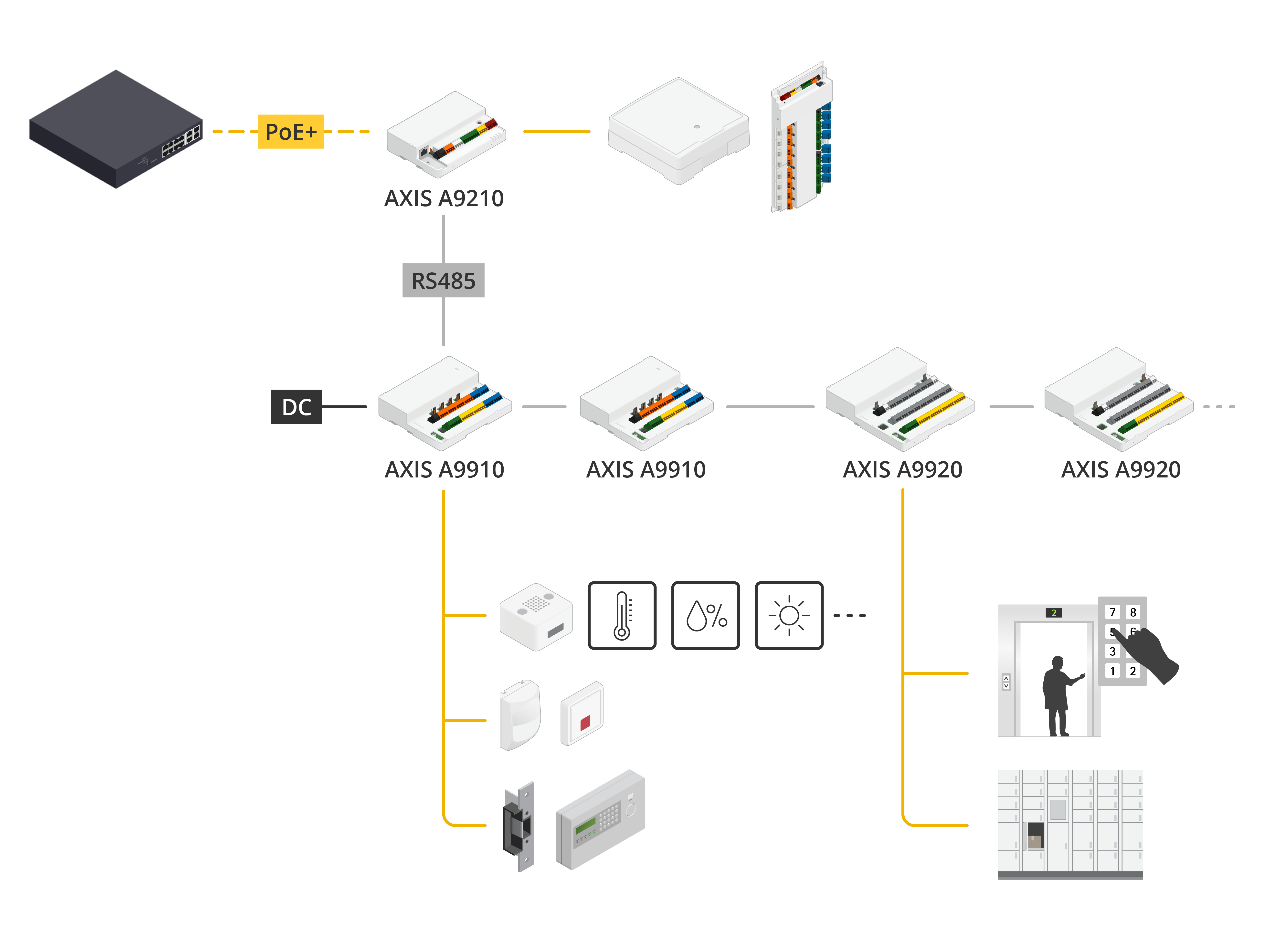
AXIS A9920 I/O and Relay Expansion Module extends the capabilities of Axis network I/O systems and can be used together with Axis door controllers or AXIS A9210 Network I/O Relay Module.
When connected to AXIS A9210, AXIS A9920 can be combined with multiple AXIS A9920 or AXIS A9910 to scale the system up to 128 I/O ports and 64 relays. This provides a flexible solution for security applications such as sensor monitoring, alarm integration, and lock control.
When used with an Axis door controller, AXIS A9920 enables advanced elevator control and cabinet control applications. A single system can support access control for up to 64 floors or controlled openings, allowing users to access only authorized areas.
Configure your device
Compatible devices
The expansion module doesn't work on its own and has no web interface.
The expansion module can be used together with compatible Axis devices, such as Axis door controllers and AXIS A9210 Network I/O Relay Module. To configure the expansion module, go to the web interface of your Axis device. For more information, see the relevant user manual of your device.
Add an encryption key
You need to set up an encryption key before you add an expansion module. The encryption key ensures the encrypted communication between your Axis device and expansion module.
- The encryption key is not visible in the system. If you generate the key, you need to export and save it in a safe place before you continue.
- To reset the encryption key, you need to reset the device to factory default. See Reset to factory default settings.
Go to the device web interface of your Axis device.
Go to Peripherals > Expansion I/O module.
Go to the expansion module and click Add encryption key.
Set up the encryption key in one of the following ways:
Under Encryption key, enter the key.
Click Generate to generate the key.
Click Export and add.
Add an expansion module
Each expansion module has a unique address, which can be configured through the DIP switch connector. See DIP switch.
Connect an expansion module to your Axis device.
Go to the web interface of your Axis device.
Set up an encryption key. See Add an encryption key.
Go to Peripherals > Expansion I/O module.
Go to the expansion module and click Add.
Enter the name, select the RS485 port if not pre-selected, and set the address for the expansion module.
Click Save.
Configure an I/O port
In the web interface of your Axis device, go to Peripherals > Expansion I/O module.
Select the expansion module and click Edit.
Rename the module.
Under I/O ports and relays, slect the I/O port and click Edit.
Rename the port.
Configure the normal state. Click for open circuit, or for closed circuit.
To configure the I/O port as input:
Under Direction, click .
To monitor the input state, turn on Supervised. See Supervised inputs.
- Note
In APIs, the supervised I/O ports work differently from the supervised input ports. For more information, go to the VAPIX® Library.
To configure the I/O port as output:
Under Direction, click .
Turn on Output state to activate the output.
Click Save.
Configure a relay
In the web interface of your Axis device, go to Peripherals > Expansion I/O module.
Select the expansion module and click Edit.
Rename the module.
Under I/O ports and relays, select the relay and click Edit.
Rename the relay.
Turn on Relay.
Click Save.
Elevator control
With a reader inside the elevator cabin, you can control the floor access by using the door controller and Axis expansion module.
You can connect up to 64 floors linked to a single door controller and Axis expansion modules:
The expansion modules use one reader port on the controller.
The other reader port is used by the reader placed inside the elevator cabin.
For wiring diagrams, see Expansion connector and Relay connector.
Specifications
Product overview
- Grounding position
- DIP switch
- DC out over current status LED
- Power status LED
- Expansion status LED
- Status LED Auxiliary connector
- DC IN connector
- DC OUT jumper
- Control button
- DC OUT connector
- Relay connector
- I/O connector
- Expansion connector
LED indicators
| LED | Color | Indication |
| Status (STAT) | Green | Blinks (on for 1 second, off for 1 second) when offline. |
| Green | Blinks (blink for 2 times, off for 2 seconds) when online with encrypted communication. | |
| Red | Blinks green/red during device software upgrade. | |
| Expansion network (EXP NET) | Green | Blinks when transmitting data. |
| Power (PWR) | Green | Normal operation. |
| DC out over current (DCOUT OC) | Red | Over current or under voltage fault on any DC out port. |
For more status LED indicators, see Troubleshoot status LEDs.
Buttons
Control button
- The control button is used for:
Resetting the product to factory default settings. See Reset to factory default settings.
Connectors
Expansion connector
6-pin terminal block used for communication between additional expansion units or main unit.
EXP IN: communication from main or already connected expansion unit.
EXP OUT: provides communication to the next expansion unit.
| Function | Pin | Specifications | |
| EXP IN | DC ground (GND) | 1 | 0 V DC |
| A | 2 | ||
| B | 3 | ||
| EXP OUT | DC ground (GND) | 4 | 0 V DC |
| A | 5 | ||
| B | 6 |
AXIS A9920 connected to AXIS A9210
Application: Connecting AXIS A9920 to AXIS A9210 for security I/O applications
Requirements:
Cable requirements: AWG: 24–16, one shielded twisted pair, 120 ohm impedance, qualified for up to 1000 m (3,280 ft).
When using a GND cable between multiple grounding points, we recommend using a ground resistor to minimize ground loops and reduce the risk of communication disturbances.
AXIS A9920 connected to Axis door controller
Application: Connecting AXIS A9920 to Axis door controller for elevator access control applications
Requirements:
AXIS A9920 requires an external power supply.
Cable requirements: AWG: 24–16, one shielded twisted pair, 120 ohm impedance, qualified for up to 1000 m (3,280 ft).
When using a GND cable between multiple grounding points, we recommend using a ground resistor to minimize ground loops and reduce the risk of communication disturbances.
AXIS A9920 multi-drop connection
Application: Connecting multiple AXIS A9920 modules using the expansion connector
Requirements:
Each AXIS A9920 requires its own external power supply.
Qualified for up to 128 I/Os and 64 relays or max 16 expansion modules.
Cable requirements: AWG: 24–16, one shielded twisted pair, 120 ohm impedance, qualified for up to 1000 m (3,280 ft).
When using a GND cable between multiple grounding points, we recommend using a ground resistor to minimize ground loops and reduce the risk of communication disturbances.
Assign a unique address for each AXIS A9920 expansion module on the same bus using the DIP switch.
Enable the termination resistor on the last module on the same bus using the DIP switch.
Power connector

DC IN
2-pin terminal block for DC power input. Use a Safety Extra Low Voltage (SELV) compliant limited power source (LPS) with either a rated output power limited to ≤100 W or a rated output current limited to ≤5 A.
| Function | Pin | Notes | Specifications |
| DC ground (GND) | 1 | 0 V DC | |
| DC input (12–24 V) | 2 | Provides power to the device. This pin can only be used as power in. | 12–24 V DC, max 30 W |
UL: DC power to be supplied by a UL 603 listed power supply, depending on application, with appropriate ratings.
External power supply for AXIS A9920
Application: Powering AXIS A9920 with an external power supply connected to the DC IN connector
Requirements:
12–24 V DC, max 30 W
Cable requirements: AWG: 18–16, qualified for up to 3 m (10 ft).
AXIS A9210 powering AXIS A9920
Application: Powering AXIS A9920 from AXIS A9210 relay power output
Before installation, verify AXIS A9210 output capability in its datasheet and configure AXIS A9920 DIP switches according to the AXIS A9920 installation guide.
Requirements:
Configure AXIS A9920 for low-power mode using the DIP switches. See AXIS A9920 installation guide for the correct DIP switch settings
Cable requirements: AWG: 18–16, qualified for up to 3 m (10 ft).
DC OUT
Two 2-pin terminal blocks for DC power output. Use a Safety Extra Low Voltage (SELV) compliant limited power source (LPS) with either a rated output power limited to ≤100 W or a rated output current limited to ≤5 A.
| Function | Pin | Notes | Specifications |
| DC ground (GND) | 1 | 0 V DC | |
| DC output (12/24 V) | 2 | Provides power to connected device. | 12/24 V DC, jumper configurable, Output power is set with DIP Switch. |
UL: DC power to be supplied by a UL 603 listed power supply, depending on application, with appropriate ratings.
DC OUT jumper
When the DC OUT jumper is fitted, it connects 12 V DC or 24 V DC to the DC out pin.
It can be used to supply power to connected devices up to a maximum of 25 W.
By default, there is no power from DC OUT. To activate DC output, set the DC OUT jumper to 12 V DC or 24 V DC.
| Power source | Max power at 12 V DC | Max power at 24 V DC |
| DC IN | 2 A (combined total) | 1 A (combined total) |
REX sensor powered from DC OUT
Application: AXIS A9920 DC OUT to power an external device, such as a REX sensor
Requirements:
Check the technical specification of the external device
DC Out when AXIS A9920 powered by:
External power supply: 12/24 V DC output, jumper configurable, max 25 W (DIP switch configuration).
AXIS A9910 relay output: 12/24 V DC output, jumper configurable, max 6 W (DIP switch configuration).
Cable requirements: AWG: 18–16. Maximum cable length depends on the connected device's voltage requirements and cable voltage drop. See the third-party device specification.
Relay connector
16 3-pin terminal blocks for form C relays that can be used, for example, to control a lock or an interface to a gate. If used with an inductive load, for example a lock, connect a diode in parallel with the load to protect against voltage transients.
These are dry contact relays only.
| Function | Pin | Notes | Specifications |
| NO | 1 | Normally open. For connecting relay devices. Connect a fail-secure lock between NO and DC ground. The three relay pins are galvanically separated from the rest of the circuitry if the jumpers are not used. | Max 4 A at 12 V DC or 2A at 30 V DC |
| COM | 2 | Common The three relay pins are galvanically separated from the rest of the circuitry if the jumpers are not used. | |
| NC | 3 | Normally closed. For connecting relay devices. Connect a fail-safe lock between NC and DC ground. The three relay pins are galvanically separated from the rest of the circuitry if the jumpers are not used. |
Lock connection, powered by external power supplier
Application: Lock connection to AXIS A9920 relay output, dry only
Requirements:
Check the technical specification of the lock devices
The lock needs to be externally powered.
Power through relay: max 4 A at 12 V DC, or 2 A at 30 V DC, dry application.
Cable requirements: AWG: 18–16.
Lock connection, powered by DC OUT
Application: Lock connection to AXIS A9920 relay output, and powering the lock using the DC OUT of AXIS A9920
Requirements:
Check the technical specification of the lock devices
DC Out when AXIS A9920 powered by:
External power supply: 12/24 V DC output, jumper configurable, max 25 W (DIP switch configuration).
AXIS A9910 relay output: 12/24 V DC output, jumper configurable, max 6 W (DIP switch configuration).
Cable requirements: AWG: 18–16. Maximum cable length depends on the connected device's voltage requirements and cable voltage drop. See the third-party device specification.
Elevator control
Application: Using the AXIS A9920 relay outputs as part of an elevator control solution. AXIS A9920 is connected to an Axis door controller to control floor access through the elevator system
Requirements:
Must be connected and configured together with an Axis door controller. See "AXIS A9920 connected to Axis door controller” in Expansion connector for connection details. Dry only relay.
Cable requirements: AWG: 18–16.
DIP switch
8-pin terminal block
| 1 | 2 | 3 | 4 | 5 | 6 | 7 | 8 | Description |
| OFF | OFF | OFF | OFF | Address 0 | ||||
| ON | OFF | OFF | OFF | Address 1 | ||||
| OFF | ON | OFF | OFF | Address 2 | ||||
| ON | ON | OFF | OFF | Address 3 | ||||
| OFF | OFF | ON | OFF | Address 4 | ||||
| ON | OFF | ON | OFF | Address 5 | ||||
| OFF | ON | ON | OFF | Address 6 | ||||
| ON | ON | ON | OFF | Address 7 | ||||
| OFF | OFF | OFF | ON | Address 8 | ||||
| ON | OFF | OFF | ON | Address 9 | ||||
| OFF | ON | OFF | ON | Address 10 | ||||
| ON | ON | OFF | ON | Address 11 | ||||
| OFF | OFF | ON | ON | Address 12 | ||||
| ON | OFF | ON | ON | Address 13 | ||||
| OFF | ON | ON | ON | Address 14 | ||||
| ON | ON | ON | ON | Address 15 | ||||
| OFF | 120 Ohm RS485 termination disabled | |||||||
| ON | 120 Ohm RS485 termination enabled | |||||||
| OFF | OFF | DC out power (Default - High: 25 W) | ||||||
| OFF | ON | DC out power ( Low: 6 W) | ||||||
| ON | OFF | DC out power ( Medium: 15 W) | ||||||
| ON | ON | DC out power ( High: 25 W) | ||||||
| ON/OFF | Not used |
Power off your device before changing the DIP switch settings.
I/O connector
Use the auxiliary connector with external devices in combination with, for example, motion detection, event triggering, and alarm notifications. In addition to the 0 V DC reference point and power (DC output), the auxiliary connector provides the interface to:
- Digital input
- For connecting devices that can toggle between an open and closed circuit, for example PIR sensors, door/window contacts, and glass break detectors.
- Supervised input
- Enables possibility to detect tampering on a digital input.
- Digital output
- For connecting external devices such as relays and LEDs. Connected devices can be activated by the VAPIX® Application Programming Interface or from the device’s web interface.
Four 6-pin terminal blocks
| Function | Pin | Notes | Specifications |
| DC ground (GND) | 1 | 0 V DC | |
| Configurable inputs or outputs | 2–3 | Digital input or supervised input – Connect to pin 1 or pin 4 to activate, or leave floating (unconnected) to deactivate. To use supervised input, install end-of-line resistors. See connection diagram for information about how to connect the resistors. | 0 to max 30 V DC |
| Digital output – Internally connected to pin 1 or pin 4 (DC ground) when active, and floating (unconnected) when inactive. If used with an inductive load, e.g., a relay, connect a diode in parallel with the load, to protect against voltage transients. They can drive a maximum of 0–30 V DC, 100 mA each. | 0 to max 30 V DC, open drain, 100 mA | ||
| DC ground (GND) | 4 | 0 V DC | |
| Configurable inputs or outputs | 5–6 | Digital input or supervised input – Connect to pin 1 or pin 4 to activate, or leave floating (unconnected) to deactivate. To use supervised input, install end-of-line resistors. See connection diagram for information about how to connect the resistors. | 0 to max 30 V DC |
| Digital output – Internally connected to pin 1 or pin 4 (DC ground) when active, and floating (unconnected) when inactive. If used with an inductive load, e.g., a relay, connect a diode in parallel with the load, to protect against voltage transients. They can drive a maximum of 0–30 V DC, 100 mA each. | 0 to max 30 V DC, open drain, 100 mA |
I/O connection
- I/O connector: DC ground
- I/O connector: Configurable I/O
- I/O connector: I/O configured as input
- I/O connector: DC ground
- I/O connector: Configurable I/O
- I/O connector: I/O configured as output
- DC OUT connector: DC ground
- DC OUT connector: External DC output 12 V
Application: Connecting I/O devices to the I/O connector and configuring them as input or output
Requirements:
Configured as output:
0 to max 30 V DC, open drain, 100 mA
DC Out when AXIS A9920 powered by:
External power supply: 12/24 V DC output, jumper configurable, max 25 W (DIP switch configuration).
AXIS A9910 relay output: 12/24 V DC output, jumper configurable, max 6 W (DIP switch configuration).
Cable Requirements: Maximum cable length depends on the connected device's voltage requirements and cable voltage drop. See the third-party device specification.
Configured as input:
0 to max 30 V DC
Cable requirements: AWG 24–16, qualified for up to 200 m (656 ft)
Supervised inputs
To use supervised inputs, install end of line resistors according to the diagram below.
Parallel first connection
The resistor values must be 4.7 kΩ and 22 kΩ.
Serial first connection
The resistor values must be the same and possible values are 1 kΩ, 2.2 kΩ, 4.7 kΩ and 10 kΩ, 1%, ¼ watt standard.
It is recommended to use twisted and shielded cables. Connect shielding to 0 V DC.
Application: Resistors connected in series or parallel at the end of line to detect the state of the circuit (ON, OFF, Open and Short)
Requirements:
Connected closer to the input device.
Parallel first connection:
Resistor values must be 4.7 K Ohm and 22 K Ohm, 1%, ¼% watt standard
Serial first connection:
Resistor vales needs to be same
1 k Ohm, 2.2 K Ohm, 4.7 K Ohm, and 10 K Ohm, 1%, ¼% watt standard
| Status | Description |
| Open | The supervised switch is in open mode. |
| Closed | The supervised switch is in closed mode. |
| Short | The I/O 1-16 cable is short circuit to GND. |
| Cut | The I/O 1-16 cable is cut and left open with no current path to GND. |
Troubleshooting
Reset to factory default settings
Disconnect power from the product.
Press and hold the control button while reconnecting power. See Product overview.
Keep the control button pressed for 5 seconds.
Release the control button. The process is complete when the status LED indicator turns green. The product has been reset to the factory default settings.
Check the current device software version
Device software determines the functionality of network devices. When you troubleshoot a problem, we recommend you to start by checking the current device software version. The latest version might contain a correction that fixes your particular problem.
To check the current version:
Go to the web interface of your Axis device.
Go to Peripherals > Expansion I/O module.
Go to the expansion module and see the current version.
Upgrade the device software
- Preconfigured and customized settings are saved when you upgrade the device software (provided that the features are available in the new version) although this is not guaranteed by Axis Communications AB.
- Make sure the device remains connected to the power source throughout the upgrade process.
When you upgrade the device with the latest version, the product receives the latest functionality available. Always read the upgrade instructions and release notes available with each new release before you upgrade the version. To find the latest device software and the release notes, go to axis.com/support/device-software.
Optional: download the device software file to your computer, available free of charge at axis.com/support/device-software.
Log in to your Axis device as an administrator.
Go to Peripherals > Expansion I/O module.
Select the expansion module and click Upgrade.
Choose to use the bundled device software or upload your own device software.
- When the upgrade has finished, the product restarts automatically.
Technical issues, clues, and solutions
If you can’t find what you’re looking for here, try the troubleshooting section at axis.com/support.
| Problems upgrading the device software | |
Upgrade failure | If the upgrade fails, the device reloads the previous version. The most common reason is that the wrong device software file has been uploaded. Check that the name of the file corresponds to your device and try again. |
Troubleshoot status LEDs
| Color | Indication |
| Blinks green (1 green 200 ms blink, off until 2 seconds) | The device is online with unencrypted communication. |
| Blinks green (2 green 200 ms blinks, off until 2 seconds) | The device is online with encrypted communication. |
| Blinks green (on for 250 ms, off for 250 ms) | Bootloader is running. |
| Blinks green and red (blinks green for 250 ms, then red for 250 ms) | New application. |
| Blinks red (2 red 200 ms blinks, off until 3 seconds) | Hardware initialization error. |
| Blinks red (3 red 200 ms blinks, off until 3 seconds) | Storage initialization error. |
| Blinks red (4 red 200 ms blinks, off until 3 seconds) | Secure element initialization error. |
| Blinks green (on for 100 ms, off for 100 ms) | The control button is pressed. |
| Blinks red (on for 100 ms, off for 100 ms) | The control button is pressed over 60 seconds. |
Contact support
If you need more help, go to axis.com/support.