This manual describes how you make the device accessible to your audio system, and how to configure the device directly from its interface.
If you are using an audio or video management software, you can use that software for configuring the device. The following management software are available for controlling your audio system:
AXIS Audio Manager Edge — Audio management software for small systems. Comes pre-installed on all audio devices with a firmware equal to or higher than 10.0.
To find Axis devices on the network and assign them IP addresses in Windows®, use AXIS IP Utility or AXIS Device Manager. Both applications are free and can be downloaded from axis.com/support.
The default administrator username is root. If the password for root is lost, reset the device to factory default settings. See Reset to factory default settings
Support tip: Password security confirmation check
Type a password. Follow the instructions about secure passwords. See Secure passwords.
Retype the password to confirm the spelling.
Click Save. The password has now been configured.
Secure passwords
Important
Use HTTPS (which is enabled by default) to set your password or other sensitive configurations over the network. HTTPS enables secure and encrypted network connections, thereby protecting sensitive data, such as passwords.
The device password is the primary protection for your data and services. Axis devices do not impose a password policy as they may be used in various types of installations.
To protect your data we strongly recommend that you:
Use a password with at least 8 characters, preferably created by a password generator.
Don’t expose the password.
Change the password at a recurring interval, at least once a year.
Additional settings
Test the impedance
Test the impedance after you have connected the speaker and before you use the amplifier for the first time or when you have changed the speaker setup, connected to the amplifier. The SPK LED will flash green when an impedance test is required. Perform the impedance test by pressing the control button until you hear tones from the speaker.
Set up direct SIP (P2P)
Use peer-to-peer when the communication is between a few user agents within the same IP network and there is no need for extra features that a PBX-server could provide.
For more information about setting options, see SIP.
Go to System > SIP > SIP settings and select Enable SIP.
To allow the device to receive incoming calls, select Allow incoming calls.
Under Call handling, set the timeout and duration for the call.
Under Ports, enter the port numbers.
SIP port – The network port used for SIP communication. The signaling traffic through this port is non-encrypted. The default port number is 5060. Enter a different port number if required.
TLS port – The network port used for encrypted SIP communication. The signaling traffic through this port is encrypted with Transport Layer Security (TLS). The default port number is 5061. Enter a different port number if required.
RTP start port – Enter the port used for the first RTP media stream in a SIP call. The default start port for media transport is 4000. Some firewalls might block RTP traffic on certain port numbers. A port number must be between 1024 and 65535.
Under NAT traversal, select the protocols you want to enable for NAT traversal.
Note
Use NAT traversal when the device is connected to the network from behind a NAT router or a firewall. For more information see NAT traversal.
Under Audio, select at least one audio codec with the desired audio quality for SIP calls. Drag-and-drop to change the priority.
Under Additional, select additional options.
UDP-to-TCP switching – Select to allow calls to switch transport protocols from UDP (User Datagram Protocol) to TCP (Transmission Control Protocol) temporarily. The reason for switching is to avoid fragmentation, and the switch can take place if a request is within 200 bytes of the maximum transmission unit (MTU) or larger than 1300 bytes.
Allow via rewrite – Select to send the local IP address instead of the router's public IP address.
Allow contact rewrite – Select to send the local IP address instead of the router's public IP address.
Register with server every – Set how often you want the device to register with the SIP server for the existing SIP accounts.
DTMF payload type – Changes the default payload type for DTMF.
Click Save.
Set up SIP through a server (PBX)
Use a PBX-server when user agents will communicate within and outside the IP network. Additional features could be added to the setup depending on the PBX-provider.
For more information about setting options, see SIP.
Request the following information from your PBX provider:
User ID
Domain
Password
Authentication ID
Caller ID
Registrar
RTP start port
To add a new account, go to System > SIP > SIP accounts and click + Account.
Enter the details you received from your PBX provider.
Select Registered.
Select a transport mode.
Click Save.
Set up the SIP settings the same way as for peer-to-peer. See Set up direct SIP (P2P) for more information.
Set up rules for events
You can create rules to make your device perform actions when certain events occur. A rule consists of conditions and actions. The conditions can be used to trigger the actions. For example, the device can play an audio clip according to a schedule or when it receives a call, or send an email if the device changes IP address.
This example explains how to set up the audio device to play an audio clip when an Axis network camera detects motion.
Prerequisites
The Axis audio device and Axis network camera are located on the same network.
The motion detection application is configured and running in the camera.
Prepare an audio clip link:
Go to Audio > Audio clips.
Click > Create link for an audio clip.
Set the volume and number of times to repeat the clip.
Click the copy icon to copy the link.
Create an action rule:
Go to System > Events > Recipients.
Click + Add recipient.
Type a name for the recipient, for example “Speaker”.
Select HTTP from the Type drop-down list.
Paste the configured link from the audio device in the URL field.
Enter the user name and password of the audio device.
Click Save.
Go to Rules and click + Add a rule.
Type a name for the action rule, for example "Play clip".
From the Condition list, select a video motion detection alternative under Applications.
Note
If there are no options for video motion detection, then go to Apps, click AXIS Video Motion Detection and turn on motion detection.
From the Action list, select Send notification through HTTP.
Under Recipient, select your recipient.
Click Save.
Stop audio with DTMF
This example explains how to:
Configure DTMF on a device.
Set up an event to stop the audio when a DTMF command is sent to the device.
Go to System > SIP > SIP settings.
Make sure Enable SIP is turned on.
If you need to turn it on, remember to click Save afterwards.
Go to SIP accounts.
Next to the SIP account, click > Edit.
Under DTMF, click + DTMF sequence.
Under Sequence, enter "1".
Under Description, enter "stop audio".
Click Save.
Go to System > Events > Rules and click + Add a rule.
Under Name, enter "DTMF stop audio".
Under Condition, select DTMF.
Under DTMF Event ID, select stop audio.
Under Action, select Stop playing audio clip.
Click Save.
Set up audio for incoming SIP calls
You can set up a rule that plays an audio clip when you receive a SIP call.
You can also set up an additional rule that answers the SIP call automatically after the audio clip has ended. This can be useful in cases where an alarm operator wants to call the attention of someone near an audio device and establish a line of communication. This is done by making a SIP call to the audio device, which will play an audio clip to alert the persons near the audio device. When the audio clip has stopped playing, the SIP call is automatically answered by the audio device and communication between the alarm operator and the persons near the audio device can take place.
Enable SIP settings:
Go to the device interface of the speaker, by entering its IP address in a web browser.
Go to System > SIP > SIP settings and select Enable SIP.
To allow the device to receive incoming calls, select Allow incoming calls.
Click Save.
Go to SIP accounts.
Next to the SIP account, click > Edit.
Uncheck Answer automatically.
Play audio when a SIP call is received:
Go to Settings > System > Events > Rules and add a rule.
Type a name for the rule.
In the list of conditions, select State.
In the list of states, select Ringing.
In the list of actions, select Play audio clip.
In the list of clips, select the audio clip you want to play.
Select how many times to repeat the audio clip. 0 means “play once”.
Click Save.
Answer the SIP call automatically after the audio clip has ended:
Go to Settings > System > Events > Rules and add a rule.
Type a name for the rule.
In the list of conditions, select Audio clip playing.
Check Use this condition as a trigger.
Check Invert this condition.
Click + Add a condition to add a second condition to the event.
In the list of conditions, select State.
In the list of states, select Ringing.
In the list of actions, select Answer call.
Click Save.
Learn more
Session Initiation Protocol (SIP)
The Session Initiation Protocol (SIP) is used to set up, maintain and terminate VoIP calls. You can make calls between two or more parties, called SIP user agents. To make a SIP call you can use, for example, SIP phones, softphones or SIP-enabled Axis devices.
The actual audio or video is exchanged between the SIP user agents with a transport protocol, for example RTP (Real-Time Transport Protocol).
You can make calls on local networks using a peer-to-peer setup, or across networks using a PBX.
Peer-to-peer SIP (P2PSIP)
The most basic type of SIP communication takes place directly between two or more SIP user agents. This is called peer-to-peer SIP (P2PSIP). If it takes place on a local network, all that’s needed are the SIP addresses of the user agents. A typical SIP address in this case would be sip:<local-ip>.
Example
You can set up a SIP-enabled phone to call an audio device on the same network using a peer-to-peer SIP setup.
Private Branch Exchange (PBX)
When you make SIP calls outside your local IP network, a Private Branch Exchange (PBX) can act as a central hub. The main component of a PBX is a SIP server, which is also referred to as a SIP proxy or a registrar. A PBX works like a traditional switchboard, showing the client's current status and allowing for example call transfers, voicemail, and redirections.
The PBX SIP server can be set up as a local entity or offsite. It can be hosted on an intranet or by a third party provider. When you make SIP calls between networks, calls are routed through a set of PBXs, that query the location of the SIP address to be reached.
Each SIP user agent registers with the PBX, and can then reach the others by dialing the correct extension. A typical SIP address in this case would be sip:<user>@<domain> or sip:<user>@<registrar-ip>. The SIP address is independent of its IP address and the PBX makes the device accessible as long as it is registered to the PBX.
Example
NAT traversal
Use NAT (Network Address Translation) traversal when the Axis device is located on an private network (LAN) and you want to access it from outside of that network.
Note
The router must support NAT traversal and UPnP®.
Each NAT traversal protocol can be used separately or in different combinations depending on the network environment.
ICE The ICE Interactive Connectivity Establishment) protocol increases the chances of finding the most efficient path to successful communication between peer devices. If you also enable STUN and TURN, you improve the ICE protocol’s chances.
STUN - STUN (Session Traversal Utilities for NAT) is a client-server network protocol that lets the Axis device determine if it is located behind a NAT or firewall, and if so obtain the mapped public IP address and port number allocated for connections to remote hosts. Enter the STUN server address, for example, an IP address.
TURN - TURN (Traversal Using Relays around NAT) is a protocol that lets a device behind a NAT router or firewall receive incoming data from other hosts over TCP or UDP. Enter TURN server address and the login information.
Analytics and apps
With analytics and apps you can get more out of your Axis device. AXIS Camera Application Platform (ACAP) is an open platform that makes it possible for third parties to develop analytics and other apps for Axis devices. Apps can be preinstalled on the device, available for download for free, or for a license fee.
To find the user manuals for Axis analytics and apps, go to help.axis.com.
To read about all the features and settings available in the web interface of devices with AXIS OS, go to AXIS OS web interface help.
Troubleshooting
Reset to factory default settings
Important
Reset to factory default should be used with caution. A reset to factory default resets all settings, including the IP address, to the factory default values.
To reset the product to the factory default settings:
Disconnect power from the product.
Press and hold the control button while reconnecting power. See Product overview.
Keep the control button pressed for 10 seconds until the status LED indicator turns amber for the second time.
Release the control button. The process is complete when the status LED indicator turns green. The product has been reset to the factory default settings. If no DHCP server is available on the network, the default IP address is 192.168.0.90
Use the installation and management software tools to assign an IP address, set the password, and access the product.
It is also possible to reset parameters to factory default through the web interface. Go to Maintenance > Maintenance actions and click Restore to reset to factory default values but keep the IP address, or Default to reset all values including the IP address.
Check the current firmware
Firmware is the software that determines the functionality of network devices. One of your first actions when you troubleshoot a problem should be to check the current firmware version. The latest version may contain a correction that fixes your particular problem.
To check the current firmware:
In the device’s webpage, go to Overview.
Check the Firmware version.
Upgrade the firmware
Important
Preconfigured and customized settings are saved when the firmware is upgraded (provided that the features are available in the new firmware), although this is not guaranteed by Axis Communications AB.
Important
Make sure the device remains connected to the power source throughout the upgrade process.
Note
When you upgrade the device with the latest firmware, the device receives the latest functionality available. Always read the upgrade instructions and release notes available with each new release before you upgrade the firmware. To find the latest firmware and the release notes, go to axis.com/support/firmware
Download the latest firmware file to your computer, available free of charge at axis.com/support/firmware
Log in to the device as an administrator.
Go to System > Maintenance > Firmware upgrade and follow the instructions on the page. When the upgrade has finished, the device restarts automatically.
Technical issues, clues and solutions
If you can’t find what you’re looking for here, try the troubleshooting section at axis.com/support.
Problems upgrading the firmware
Firmware upgrade failure
If the firmware upgrade fails, the device reloads the previous firmware. The most common reason is that the wrong firmware file has been uploaded. Check that the name of the firmware file corresponds to your device and try again.
Problems setting the IP address
The device is located on a different subnet
If the IP address intended for the device and the IP address of the computer used to access the device are located on different subnets, you cannot set the IP address. Contact your network administrator to obtain an IP address.
The IP address is being used by another device
Disconnect the Axis device from the network. Run the ping command (in a Command/DOS window, type ping and the IP address of the device):
If you receive: Reply from <IP address>: bytes=32; time=10... this means that the IP address may already be in use by another device on the network. Obtain a new IP address from the network administrator and reinstall the device.
If you receive: Request timed out, this means that the IP address is available for use with the Axis device. Check all cabling and reinstall the device.
Possible IP address conflict with another device on the same subnet
The static IP address in the Axis device is used before the DHCP server sets a dynamic address. This means that if the same default static IP address is also used by another device, there may be problems accessing the device.
The device cannot be accessed from a browser
Cannot log in
When HTTPS is enabled, ensure that the correct protocol (HTTP or HTTPS) is used when attempting to log in. You may need to manually type http or https in the browser’s address field.
If the password for the user root is lost, the device must be reset to the factory default settings. See Reset to factory default settings.
The IP address has been changed by DHCP
IP addresses obtained from a DHCP server are dynamic and may change. If the IP address has been changed, use AXIS IP Utility or AXIS Device Manager to locate the device on the network. Identify the device using its model or serial number, or by the DNS name (if the name has been configured).
The device is accessible locally but not externally
To access the device externally, we recommend using one of the following applications for Windows®:
AXIS Camera Station: 30-day trial version free of charge, ideal for small to mid-size systems.
For instructions and download, go to axis.com/vms.
Problems with sound files
Can’t upload media clip
The following audio clip formats are supported:
au file format, encoded in µ-law and sampled with 8 or 16 kHz.
wav file format, encoded in PCM audio. It supports encoding as 8 or 16-bit mono or stereo and sample rate of 8 to 48 kHz.
mp3 file format, in mono or stereo with bitrate of 64 kbps to 320 kbps and sample rate of 8 to 48 kHz.
Media clips are played with different volumes
A sound file is recorded with a certain gain. If your audio clips have been created with different gains, they will be played with a different loudness. Make sure that you use clips that have the same gain.
Performance considerations
When you set up your system, it’s important to consider how different settings and situations affect the required bandwidth (bitrate).
The most important factors to consider:
Heavy network utilization due to poor infrastructure affects the bandwidth.
Running multiple AXIS Camera Application Platform (ACAP) applications simultaneously may affect the general performance.
Specifications
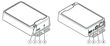
Product overview
Status LED indicator
Speaker LED
SD memory card slot
Control button
I/O connector
Audio-in connector
Speaker connector
Network connector
LED indicators
Status LED
Indication
Green
Steady for normal operation.
Amber
Steady during startup. Flashes during device software upgrade or reset to factory default.
Amber/Red
Flashes if network connection is unavailable or lost.
Red
Flashes slowly if upgrade failed.
Red/Green
Flashes fast when Locate device is selected.
SPK LED
Indication
Green
Steady green for normal operation. Flashes (two short green flashes and one long without light) when the impedance has not been calibrated.
Red
Flashes red when the overcurrent protection has been tripped.
SD card slot
NOTICE
Risk of damage to SD card. Don’t use sharp tools, metal objects, or excessive force when inserting or removing the SD card. Use your fingers to insert and remove the card.
Risk of data loss and corrupted recordings. Unmount the SD card from the device’s web interface before removing it. Don’t remove the SD card while the product is running.
microSD, microSDHC, and microSDXC Logos are trademarks of SD-3C LLC. microSD, microSDHC, microSDXC are trademarks or registered trademarks of SD-3C, LLC in the United States, other countries or both.
Buttons
Control button
Press the control button to perform an impedance test. Press and hold the control button until you hear tones from the speaker. See Test the impedance for more information.
Connectors
Network connector
RJ45 Ethernet connector with Power over Ethernet Plus (PoE+).
NOTICE
The product shall be connected using a shielded network cable (STP). All cables connecting the product to the network shall be intended for their specific use. Make sure that the network devices are installed in accordance with the manufacturer’s instructions. For information about regulatory requirements, see the Installation Guide at www.axis.com.
Audio connector
Audio in – 3.5 mm input for a mono microphone, or a line-in mono signal (left channel is used from a stereo signal).
1 Tip
2 Ring
3 Sleeve
Audio Input
Microphone/Line in
Microphone bias voltage
Ground
2-pin terminal block for speaker out.
Function
Pin
Notes
Speaker out (-)
1
Speaker out (+)
2
I/O connector
Use the I/O connector with external devices in combination with, for example, motion detection, event triggering, and alarm notifications. In addition to the 0 VDC reference point and power (12 V DC output), the I/O connector provides the interface to:
Digital input
For connecting devices that can toggle between an open and closed circuit, for example PIR sensors, door/window contacts, and glass break detectors.
Digital output
For connecting external devices such as relays and LEDs. Connected devices can be activated by the VAPIX® Application Programming Interface, through an event or from the device’s web interface.
4-pin terminal block
Function
Pin
Notes
Specifications
DC ground
1
0 VDC
DC output
2
Can be used to power auxiliary equipment. Note: This pin can only be used as power out.
12 VDC Max load = 50 mA
Configurable (Input or Output)
3–4
Digital input – Connect to pin 1 to activate, or leave floating (unconnected) to deactivate.
0 to max 30 VDC
Digital output – Internally connected to pin 1 (DC ground) when active, and floating (unconnected) when inactive. If used with an inductive load, e.g., a relay, connect a diode in parallel with the load, to protect against voltage transients.
0 to max 30 VDC, open drain, 100 mA
Example
DC ground
DC output 12 V, max 50mA
I/O configured as input
I/O configured as output
API commands
VAPIX® is Axis’ own open API (Application Programming Interface). You can control almost all functionality available in Axis devices through VAPIX®. To get access to the complete VAPIX® documentation, join Axis Developer Community at axis.com/developer-community
Enter the commands in a web browser, and replace <deviceIP> with the IP address or host name of your device.
Important
The API commands execute immediately. If you restore or reset your device all settings will be lost. For example action rules.
Example
Restart the device
Request
http://<deviceIP>/axis-cgi/restart.cgi
Example
Restore the device. The request returns most settings to default values, but keeps the IP number.
Request
http://<deviceIP>/axis-cgi/factorydefault.cgi
Example
Reset the device. The request returns all settings including IP number to default values.
Cybersecurity supports a successful product lifecycle with minimized risks. You can find in-depth information and documentation about our cybersecurity approach at axis.com/about-axis/cybersecurity. Follow the cybersecurity guidelines below to receive product security notifications from Axis and to configure your product for a secure lifecycle and decommissioning.
At Axis Trust Center, you can find information about how Axis implements security compliance, transparency, data protection, and privacy.
Subscribe to Axis security notification emails at axis.com/security-notification-service. We will send you information about vulnerabilities, corresponding security advisories, and other security-related matters for your Axis product.
Secure product lifecycle
Axis minimizes risks throughout the lifetime of our products through secure lifecycle management. Use our hardening guides at help.axis.com to more securely configure and operate your Axis products and to find information about:
Secure first-use
Axis products are pre-configured with high default protection to allow for secure initialization and encrypted communication from the very start.
Intended use and common configuration mistakes
Our guides provide information about the intended usage of Axis products, including common security-relevant misuse and configuration mistakes that should be avoided.
Managing vulnerabilities and supply chain transparency
A Software Bill of Material (SBOM) is published with every software release on axis.com to disclose vulnerabilities and improve supply chain transparency.
Decommissioning and the secure erasure of data
To securely decommission a product when it reaches the end of its lifecycle, reset it to factory default settings. This erases your configurations, stored data, and sensitive information.