Installation
Get started
Find the device on the network
To find Axis devices on the network and assign them IP addresses in Windows®, use AXIS IP Utility or AXIS Device Manager. Both applications are free and can be downloaded from axis.com/support.
For more information about how to find and assign IP addresses, go to How to assign an IP address and access your device.
Browser support
You can use the device with the following browsers:
ChromeTM | EdgeTM | Firefox® | Safari® | |
Windows® | ✓ | ✓ | * | * |
macOS® | ✓ | ✓ | * | * |
Linux® | ✓ | ✓ | * | * |
Other operating systems | * | * | * | * |
✓: Recommended
*: Supported with limitations
Open the device's web interface
Open a browser and type the IP address or host name of the Axis device.
If you don’t know the IP address, use AXIS IP Utility or AXIS Device Manager to find the device on the network.
Type the username and password. If you access the device for the first time, you must create an administrator account. See Create an administrator account.
For descriptions of all features and settings in the web interface of devices with AXIS OS, see AXIS OS web interface help.
Create an administrator account
The first time you log in to your device, you must create an administrator account.
Enter a username.
Enter a password. See Secure passwords.
Re-enter the password.
Accept the license agreement.
Click Add account.
The device has no default account. If you lose the password for your administrator account, you must reset the device. See Reset to factory default settings.
Secure passwords
Use HTTPS (which is enabled by default) to set your password or other sensitive configurations over the network. HTTPS enables secure and encrypted network connections, thereby protecting sensitive data, such as passwords.
The device password is the primary protection for your data and services. Axis devices do not impose a password policy as they may be used in various types of installations.
To protect your data we strongly recommend that you:
Use a password with at least 8 characters, preferably created by a password generator.
Don’t expose the password.
Change the password at a recurring interval, at least once a year.
Make sure that no one has tampered with the device software
- To make sure that the device has its original AXIS OS, or to take full control of the device after a security attack:
Reset to factory default settings. See Reset to factory default settings.
After the reset, secure boot guarantees the state of the device.
Configure and install the device.
Web interface overview
This video gives you an overview of the device’s web interface.
Configure your device
Basic settings
Set the capture mode
Go to Video > Installation > Capture mode.
Click Change.
Select a capture mode and click Save and restart.
See also .
Set the power line frequency
Go to Video > Installation > Power line frequency.
Select a power line frequency and click Save and restart.
Set the orientation
Go to Video > Installation > Rotate.
Select 0 , 90, 180 or 270 degrees.
See also .
Adjust the image
This section includes instructions about configuring your device. If you want to learn more about how certain features work, go to Learn more.
Adjust the focus faster with focus recall areas
To save the focus settings at a specific pan/tilt range, add a focus recall area. Each time the camera moves into that area it recalls the previously saved focus. It’s enough to cover half of the focus recall area in the live view.
- We recommend the focus recall feature in the following scenarios:
When there is a lot of manual operation in live view, for example with a joystick.
Where PTZ preset positions with manual focus are not efficient, for example movements where the focus setting changes continuously.
In low-light scenarios, where the autofocus is challenged by the lighting conditions.
- The focus recall overrides the camera’s autofocus at the specific pan/tilt range.
- A preset position overrides the focus setting saved in the focus recall area.
- The maximum number of focus recall areas is 20.
- Create a focus recall area
Pan, tilt, and zoom into the area where you would like to have focus.
As long as the focus recall button shows a plus , you can add a focus recall area in that position.
Adjust the focus.
Click the focus recall button.
- Delete a focus recall area
Pan, tilt, and zoom into the focus recall area you want to delete.
The focus recall button toggles to minus when the camera detects a focus recall area: .
Click the focus recall button.
Handle scenes with strong backlight
Dynamic range is the difference in light levels in an image. In some cases the difference between the darkest and the brightest areas can be significant. The result is often an image where either the dark or the bright areas are visible. Wide dynamic range (WDR) makes both dark and bright areas of the image visible.
Go to Video > Image > Wide dynamic range.
Use the Local contrast slider to adjust the amount of WDR.
If you still have problems, go to Exposure and adjust the Exposure zone to cover the area of interest.
Find out more about WDR and how to use it at axis.com/solutions/wide-dynamic-range-wdr.
Hide parts of the image with privacy masks
You can create one or several privacy masks to hide parts of the image.
Go to Video > Privacy masks.
Click .
Click the new mask and type a name.
Adjust the size and placement of the privacy mask according to your needs.
To change the color for all privacy masks, click Privacy masks and select a color.
See also Privacy masks
Show the pan or tilt position as a text overlay
You can show the pan or tilt position as an overlay in the image.
Go to Video > Overlays and click .
In the text field, type
#xto show the pan position.Type
#yto show the tilt position.Choose appearance, text size, and alignment.
Include the text overlay.
The current pan and tilt positions show up in the live view image and in the recording.
Adjust the camera view (PTZ)
Limit the pan, tilt, and zoom movements
If there are parts of the scene that you don’t want the camera to reach, you can limit the pan, tilt, and zoom movements. For example, you want to protect the privacy of residents in an apartment building, which is located close to a parking lot that you intend to monitor.
To limit the movements:
Go to PTZ > Limits.
Set the limits as needed.
Create a guard tour with preset positions
A guard tour displays the video stream from different preset positions either in a predetermined or random order, and for configurable periods of time.
Go to PTZ > Guard tours.
Click Guard tour.
Select Preset position and click Create.
Under General settings:
Enter a name for the guard tour and specify the pause length between each tour.
If you want the guard tour to go to the preset positions in a random order, turn on Play guard tour in random order.
Under Step settings:
Set the duration for the preset.
Set the move speed, which controls how fast to move to the next preset.
Go to Preset positions.
Select the preset positions that you want in your guard tour.
Drag them to the View order area, and click Done.
To schedule the guard tour, go to System > Events.
View and record video
This section includes instructions about configuring your device. To learn more about how streaming and storage works, go to Streaming and storage.
Set up network storage
- To store recordings on the network, you need to set up your network storage.
Go to System > Storage.
Click Add network storage under Network storage.
Type the IP address of the host server.
Type the name of the shared location on the host server under Network share.
Type the username and password.
Select the SMB version or leave it on Auto.
Select Add share without testing if you experience temporary connection issues, or if the share is not yet configured.
Click Add.
Record and watch video
- Record video directly from the camera
Go to Video > Stream.
To start a recording, click .
If you haven’t set up any storage, click and . For instructions on how to set up network storage, see Set up network storage
To stop recording, click again.
- Watch video
Go to Recordings.
Click for your recording in the list.
Reduce bandwidth and storage
Reducing the bandwidth can lead to loss of detail in the image.
Go to Video > Stream.
Click in the live view.
Select Video format AV1 if your device supports it. Otherwise select H.264.
Go to Video > Stream > General and increase Compression.
Go to Video > Stream > Zipstream and do one or more of the following:
- Note
The Zipstream settings are used for all video encodings except MJPEG.
Select the Zipstream Strength that you want to use.
Turn on Optimize for storage. This can only be used if the video management software supports B-frames.
Turn on Dynamic FPS.
Turn on Dynamic GOP and set a high Upper limit GOP length value.
Most web browsers don’t support H.265 decoding and because of this the device doesn’t support it in its web interface. Instead you can use a video management system or application that supports H.265 decoding.
Set up rules for events
You can create rules to make your device perform an action when certain events occur. A rule consists of conditions and actions. The conditions can be used to trigger the actions. For example, the device can start a recording or send an email when it detects motion, or show an overlay text while the device is recording.
To learn more, see Get started with rules for events.
Direct the camera to a preset position when the camera detects motion
This example explains how to set up the camera to go to a preset position when it detects motion in the image.
- Make sure that AXIS Object Analytics is running:
Go to Apps > AXIS Object Analytics.
Start the application if it is not already running.
Make sure you have set up the application according to your needs.
Add a preset position:
Go to PTZ and set where you want the camera to be directed by creating a preset position.
- Create a rule:
Go to System > Events and add a rule.
Type a name for the rule.
In the list of conditions, under Application, select Object Analytics.
In the list of actions, select Go to preset position.
Select the preset position you want the camera to go to.
Click Save.
Direct the camera and open the lock to a gate when someone is nearby
This example explains how to direct the camera and open a gate when someone wants to enter during daytime. This is done by connecting a PIR detector to the product’s input port and a switch relay to the product’s output port via the multicable.
Required hardware
Multicable (sold separately), see Multiconnector.
Mounted PIR detector
Switch relay connected to the gate lock, in this case the switch is normally closed (NC)
Connecting wires
Physical connection
Remove the plug from the camera’s multi-connector and connect the multicable.
Connect the wires from the PIR detector to the input pin, see Multiconnector.
Connect the wires from the switch to the output pin, see Multiconnector.
Configure I/O ports
You need to connect the switch relay to the camera from the camera’s web interface. First, configure the I/O ports:
Set the PIR detector to an input port
Go to System > Accessories > I/O ports.
Click to set the direction to input for port 1.
Give the input module a descriptive name, for example “PIR detector”.
If you want to trigger an event whenever the PIR detector senses motion, click to set the normal state to circuit open.
Set the switch relay to an output port
Click to set the direction to output for port 2.
Give the output module a descriptive name, for example “Gate switch”.
If you want to open the gate whenever an event is triggered, click to set the normal state to circuit closed.
Create the preset position
Go to PTZ > Preset positions.
Create the preset position that covers the entrance of the gate and name it, for example, “Gate entrance”.
Create rules
For the camera to open the gate when the PIR detector senses someone nearby, you need to create a rule in the camera:
Go to System > Events and add a rule.
Type a name for the rule, for example “Open gate”.
In the list of conditions, select PIR detector.
In the list of actions, select Toggle I/O once.
In the list of ports, select Gate switch.
Set state to Active.
Set the duration.
Click Save.
Create another rule with the name “Direct the camera to the gate".
Select the same input signal as before, but as action select the previously created “Gate entrance” preset position.
Click Save.
Record video when the camera detects loud noises
This example explains how to set up the camera to start recording to the SD card five seconds before it detects loud noise and to stop two minutes after.
- Turn on audio:
Set up the stream profile to include audio, see Add audio to your recording.
- Turn on audio detection:
Go to System > Detectors > Audio detection.
Adjust the sound level according to your needs.
- Create a rule:
Go to System > Events and add a rule.
Type a name for the rule.
In the list of conditions, under Audio, select Audio Detection.
In the list of actions, under Recordings, select Record video.
In the list of storage options, select SD_DISK.
Select the stream profile where audio has been turned on.
Set the prebuffer time to 5 seconds.
Set the postbuffer time to 2 minutes.
Click Save.
Zoom in on a specific area automatically with gatekeeper
This example explains how to use the gatekeeper functionality to make the camera zoom in automatically on the license plate of a car that passes through a gate. When the car has passed, the camera zooms out to the home position.
- Create the preset positions:
Go to PTZ > Preset positions.
Create the home position that includes the entrance of the gate.
Create the zoomed-in preset position so that it covers the area in the image where you assume that the license plate will appear.
- Set up motion detection:
Go to Apps and start and open AXIS Object Analytics.
Create an object in area scenario for vehicles, with an include area that covers the entrance of the gate.
- Create a rule:
Go to System > Events and add a rule.
Name the rule “Gatekeeper”.
In the list of conditions, under Application, select the Object Analytics scenario.
In the list of actions, under Preset positions, select Go to preset position.
Select a Video channel.
Select the Preset position.
To make the camera wait a while before it returns to the home position, set a time for Home timeout.
Click Save.
Record video when the camera detects impact
Shock detection allows the camera to detect tampering caused by vibrations or shock. Vibrations due to the environment or to an object can trigger an action depending on the shock sensitivity range, which can be set from 0 to 100. In this scenario, someone is throwing rocks at the camera after hours and you would like to get a video clip of the event.
- Turn on shock detection:
Go to System > Detectors > Shock detection.
Turn on shock detection, and adjust the shock sensitivity.
- Create a rule:
Go to System > Events > Rules and add a rule.
Type a name for the rule.
In the list of conditions, under Device status, select Shock detected.
Click + to add a second condition.
In the list of conditions, under Scheduled and recurring, select Schedule.
In the list of schedules, select After hours .
In the list of actions, under Recordings, select Record video while the rule is active.
Select where to save the recordings.
Select a Camera.
Set the prebuffer time to 5 seconds.
Set the postbuffer time to 50 seconds.
Click Save.
Audio
Add audio to your recording
- Turn on audio:
Go to Video > Stream > Audio and include audio.
If the device has more than one input source, select the correct one in Source.
Go to Audio > Device settings and turn on the correct input source.
- Edit the stream profile that is used for the recording:
Go to System > Stream profiles and select the stream profile.
Select Include audio and turn it on.
Click Save.
The web interface
To read about all the features and settings available in the web interface of devices with AXIS OS, go to AXIS OS web interface help.
Learn more
Privacy masks
A privacy mask is a user-defined area that prevents users from viewing a part of the monitored area. In the video stream, privacy masks appear as blocks of solid color or blurred image elements.
The privacy mask is relative to the pan, tilt, and zoom coordinates, so regardless of where you point the camera, the privacy mask covers the same place or object.
You’ll see the privacy mask on all snapshots, recorded video, and live streams.
You can use the VAPIX® application programming interface (API) to hide the privacy masks.
If you use multiple privacy masks it may affect the product’s performance.
You can create several privacy masks. Each mask can have 3 to 10 anchor points.
Overlays
Overlays are superimposed over the video stream. They are used to provide extra information during recordings, such as a timestamp, or during product installation and configuration. You can add either text or an image.
Pan, tilt, and zoom (PTZ)
Guard tours
A guard tour displays the video stream from different preset positions either in a predetermined or random order, and for configurable periods of time. Once started, a guard tour continues to run until stopped, even when there are no clients (web browsers) viewing the images.
Streaming and storage
Video compression formats
Decide which compression method to use based on your viewing requirements, and on the properties of your network. The available options are:
Motion JPEG
Motion JPEG, or MJPEG, is a digital video sequence that is made up of a series of individual JPEG images. These images are then displayed and updated at a rate sufficient to create a stream that shows constantly updated motion. For the viewer to perceive motion video the rate must be at least 16 image frames per second. Full motion video is perceived at 30 (NTSC) or 25 (PAL) frames per second.
The Motion JPEG stream uses considerable amounts of bandwidth, but provides excellent image quality and access to every image contained in the stream.
H.264 or MPEG-4 Part 10/AVC
H.264 is a licensed technology. The Axis product includes one H.264 viewing client license. To install additional unlicensed copies of the client is prohibited. To purchase additional licenses, contact your Axis reseller.
H.264 can, without compromising image quality, reduce the size of a digital video file by more than 80% compared to the Motion JPEG format and by as much as 50% compared to older MPEG formats. This means that less network bandwidth and storage space are required for a video file. Or seen another way, higher video quality can be achieved for a given bitrate.
H.265 or MPEG-H Part 2/HEVC
H.265 can, without compromising image quality, reduce the size of a digital video file by more than 25% compared to H.264.
- H.265 is licensed technology. The Axis product includes one H.265 viewing client license. Installing additional unlicensed copies of the client is prohibited. To purchase additional licenses, contact your Axis reseller.
- Most web browsers don’t support H.265 decoding and because of this the camera doesn’t support it in its web interface. Instead you can use a video management system or application supporting H.265 decoding.
How do Image, Stream, and Stream profile settings relate to each other?
The Image tab contains camera settings that affect all video streams from the product. If you change something in this tab, it immediately affects all video streams and recordings.
The Stream tab contains settings for video streams. You get these settings if you request a video stream from the product and don’t specify for example resolution, or frame rate. When you change the settings in the Stream tab, it doesn’t affect ongoing streams, but it will take effect when you start a new stream.
The Stream profiles settings override the settings from the Stream tab. If you request a stream with a specific stream profile, the stream contains the settings of that profile. If you request a stream without specifying a stream profile, or request a stream profile that doesn't exist in the product, the stream contains the settings from the Stream tab.
Bitrate control
Bitrate control helps you to manage the bandwidth consumption of your video stream.
Variable bitrate (VBR)
Variable bitrate allows the bandwidth consumption to vary depending on the level of activity in the scene. The more activity, the more bandwidth you need. With variable bitrate you are guaranteed constant image quality, but you need to make sure you have storage margins.
Maximum bitrate (MBR)
Maximum bitrate lets you set a target bitrate to handle bitrate limitations in your system. You might see a decline in image quality or frame rate as the instantaneous bitrate is kept below the specified target bitrate. You can choose to prioritize either image quality or frame rate. We recommend that you configure the target bitrate to a higher value than the expected bitrate. This gives you a margin in case there is a high level of activity in the scene.
- Target bitrate
Average bitrate (ABR)
With average bitrate, the bitrate is automatically adjusted over a longer period of time. This is so you can meet the specified target and provide the best video quality based on your available storage. Bitrate is higher in scenes with a lot of activity, compared to static scenes. You are more likely to get better image quality when in scenes with a lot of activity if you use the average bitrate option. You can define the total storage required to store the video stream for a specified amount of time (retention time) when image quality is adjusted to meet the specified target bitrate. Specify the average bitrate settings in one of the following ways:
To calculate the estimated storage need, set the target bitrate and the retention time.
To calculate the average bitrate, based on available storage and required retention time, use the target bitrate calculator.
- Target bitrate
- Actual average bitrate
- You can also turn on maximum bitrate and specify a target bitrate within the average bitrate option.
- Target bitrate
- Actual average bitrate
Analytics and apps
With analytics and apps you can get more out of your Axis device. AXIS Camera Application Platform (ACAP) is an open platform that makes it possible for third parties to develop analytics and other apps for Axis devices. Apps can be preinstalled on the device, available for download for free, or for a license fee.
To find the user manuals for Axis analytics and apps, go to help.axis.com.
- Several apps can run at the same time but some apps might not be compatible with each other. Certain combinations of apps might require too much processing power or memory resources when run in parallel. Verify that the apps work together before deployment.
Metadata visualization
Analytics metadata is available for moving objects in the scene. Supported object classes are visualized in the video stream through a bounding box surrounding the object, along with information about the object type and confidence level of the classification. To learn more about how to configure and consume analytics metadata, see AXIS Scene Metadata integration guide.
Specifications
Product overview
Make sure the dome is attached in operation mode, otherwise focus may be affected.
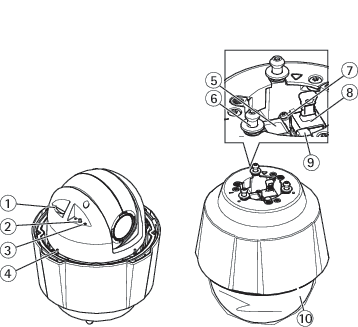
- SD memory card slot
- Control button
- Status LED indicator
- Power button
- Network connector (PoE+)
- Mounting screws (3)
- Ground screw
- Multi-connector with cover (Do not remove the cover unless an I/O-cable is connected)
- Hook for safety wire
- Dome
LED indicators
| Status LED | Indication |
| Unlit | Connection and normal operation. |
| Green | Shows steady green for 10 seconds for normal operation after startup completed. |
| Amber | Steady during startup. Flashes during device software upgrade or reset to factory default. |
| Amber/Red | Flashes amber/red if network connection is unavailable or lost. |
SD card slot
- Risk of damage to SD card. Don’t use sharp tools, metal objects, or excessive force when inserting or removing the SD card. Use your fingers to insert and remove the card.
- Risk of data loss and corrupted recordings. Unmount the SD card from the device’s web interface before removing it. Don’t remove the SD card while the product is running.
This device supports SD/SDHC/SDXC cards.
For SD card recommendations, see axis.com.
![]()
![]()
![]() SD, SDHC, and SDXC Logos are trademarks of SD-3C LLC. SD, SDHC and SDXC are trademarks or registered trademarks of SD-3C, LLC in the United States, other countries or both.
SD, SDHC, and SDXC Logos are trademarks of SD-3C LLC. SD, SDHC and SDXC are trademarks or registered trademarks of SD-3C, LLC in the United States, other countries or both.
Buttons
Control button
- The control button is used for:
Resetting the product to factory default settings. See Reset to factory default settings.
Power button
Press and hold the power button to temporarily power the product when the dome cover is removed.
The power button is also used with the control button to reset the camera to factory default settings. See Reset to factory default settings.
Connectors
Network connector
RJ45 Ethernet connector with Power over Ethernet Plus (PoE+).
Multiconnector
- Terminal connector for connecting external equipment:
Audio equipment
Input/Output (I/O) devices
AC/DC power supply
When connecting external equipment, a separately sold Axis Multicable C I/O Audio Power 1 m/ 5 m or a separately sold Axis 10-pin Push-pull System Connector is required in order to maintain the product’s IP rating. For more information, see Multicable connectors and Axis 10-pin push-pull system connector (sold separately).
Multicable connectors
- Camera multiconnector
- I/O terminal block
- Audio terminal block
- Power connector
The multicable provides the following connectors:
- Power connector
- 2-pin terminal block used for power input. The polarity of the cables does not matter. Use a Safety Extra Low Voltage (SELV) compliant limited power source (LPS) with either a rated output power limited to ≤100 W or a rated output current limited to ≤5 A.
- Audio connector
- 4–pin terminal block used for audio in and audio line out. This can be connected to a public address (PA) system or an active speaker with a built-in amplifier.
| Function | Pin | Notes |
| Audio In | 1 | Balanced or unbalanced input for a mono microphone or line signal |
| Audio Line Out | 3 | Can be connected to a public address (PA) system or an active speaker with a built-in amplifier |
| GND | 2, 4 | Ground |
- I/O terminal connector
- Use with external devices in combination with, for example, tampering alarms, motion detection, event triggering, and alarm notifications. In addition to the 0 V DC reference point and power (DC output), the I/O connector provides the interface to:
Digital output — For connecting external devices such as relays and LEDs. Connected devices can be activated by the VAPIX® Application Programming Interface or from the device’s web interface.
Digital input — For connecting external devices that can toggle between an open and closed circuit, for example PIR detectors, door/window contacts, and glass break detectors.
| Function | Pin | Notes | Specifications |
| 0 V DC (-) | 1 | 0 V DC | |
| DC output | 2 | Can be used to power auxiliary equipment. Note: This pin can only be used as power out. | 12 V DC Max load =50 mA |
| Configurable (Input or Output) | 3–6 | Digital input – Connect to pin 1 to activate, or leave floating (unconnected) to deactivate. | 0 to max 30 V DC |
| Digital output – Internally connected to pin 1 (DC ground) when active, and floating (unconnected) when inactive. If used with an inductive load, e.g. a relay, a diode must be connected in parallel with the load, for protection against voltage transients. | 0 to max 30 V DC, open drain, 100 mA |
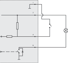
- 0 V DC (-)
- DC output 12 V, max 50 mA
- I/O configured as input
- I/O configured as output
Axis 10-pin push-pull system connector (sold separately)
When connecting external equipment to the Axis product, an Axis 10-pin Push-Pull System Connector (sold separately) is required in order to maintain the product’s IP rating.
Mounting the wires requires a crimp tool. To get detailed mounting instructions of the wires, go to axis.com/support.
Connect the 10-pin push-pull system connector to the product’s multi-connector. To locate the multi-connector go to .
10–pin push-pull system connector | |
| Function | Pin | Notes | Specifications |
| AC/DC Power input | 9, 10 | The input is polarity independent. Use a Safety Extra Low Voltage (SELV) compliant limited power source (LPS) with either a rated output power limited to ≤100 W or a rated output current limited to ≤5 A. | 24 V AC/DC |
| Configurable (Input or Output) | 3 – I/O 1 5 – I/O 2 6 – I/O 3 7 – I/O 4 | Digital input – Connect to pin 8 to activate, or leave floating (unconnected) to deactivate. | 0 to max 30 V DC |
| Digital output – Connected to pin 8 when activated, floating (unconnected) when deactivated. If used with an inductive load, e.g. a relay, a diode must be connected in parallel with the load, for protection against voltage transients. | 0 to max 30 V DC, open drain, 100 mA | ||
| DC Output | 2 | Can be used to power auxiliary equipment. Note: This pin can only be used as power out. | 12 V DC Max load = 50 mA |
| GND | 8 | Ground for audio and I/O | |
| Audio Line Out | 4 | Can be connected to a public address (PA) system or an active speaker with a built-in amplifier | |
| Audio In | 1 | Unbalanced input for a mono microphone or line signal |
Troubleshooting
Reset to factory default settings
Reset to factory default should be used with caution. A reset to factory default resets all settings, including the IP address, to the factory default values.
To reset the product to the factory default settings:
Press and hold the control button and the power button for 15–30 seconds until the status LED indicator flashes amber. See Product overview.
Release the control button but continue to hold down the power button until the status LED indicator turns green.
Release the power button and assemble the product.
The process is now complete. The product has been reset to the factory default settings. If no DHCP server is available on the network, the device IP address will default to one of the following:
Devices with AXIS OS 12.0 and later: Obtained from the link-local address subnet (169.254.0.0/16)
Devices with AXIS OS 11.11 and earlier: 192.168.0.90/24
Using the installation and management software tools to assign an IP address, set the password and access the video stream.
You can also reset parameters to factory default through the device’s web interface. Go to Maintenance > Factory default and click Default.
AXIS OS options
Axis offers device software management according to either the active track or the long-term support (LTS) tracks. Being on the active track means continuously getting access to all the latest product features, while the LTS tracks provide a fixed platform with periodic releases focused mainly on bug fixes and security updates.
Using AXIS OS from the active track is recommended if you want to access the newest features, or if you use Axis end-to-end system offerings. The LTS tracks are recommended if you use third-party integrations, which are not continuously validated against the latest active track. With LTS, the products can maintain cybersecurity without introducing any significant functional changes or affecting any existing integrations. For more detailed information about Axis device software strategy, go to axis.com/support/device-software.
Check the current AXIS OS version
AXIS OS determines the functionality of our devices. When you troubleshoot a problem, we recommend that you to start by checking the current AXIS OS version. The latest version might contain a correction that fixes your particular problem.
To check the current AXIS OS version:
Go to the device’s web interface > Status.
Under Device info, see the AXIS OS version.
Upgrade AXIS OS
- When you upgrade the device software, your preconfigured and customized settings are saved. Axis Communications AB can't guarantee that the settings are saved, even if the features are available in the new AXIS OS version.
- Starting from AXIS OS 12.6, you must install every LTS version between your device’s current version and the target version. For example, if the currently installed device software version is AXIS OS 11.2, you have to install the LTS version AXIS OS 11.11 before you can upgrade the device to AXIS OS 12.6. For more information, see AXIS OS Lifecycle guide: Upgrade path.
- Make sure the device remains connected to the power source throughout the upgrade process.
- Make sure the cover is attached during upgrade to avoid installation failure.
- When you upgrade the device with the latest AXIS OS version in the active track, the product receives the latest functionality available. Always read the upgrade instructions and release notes available with each new release before you upgrade. To find the latest AXIS OS version and the release notes, go to axis.com/support/device-software.
Download the AXIS OS file to your computer, available free of charge at axis.com/support/device-software.
Log in to the device as an administrator.
Go to Maintenance > AXIS OS upgrade and click Upgrade.
- When the upgrade has finished, the product restarts automatically.
You can use AXIS Device Manager to upgrade multiple devices at the same time. Find out more at axis.com/products/axis-device-manager.
Technical problems and possible solutions
Problems upgrading AXIS OS
AXIS OS upgrade failed If the upgrade fails, the device reloads the previous version. The most common reason is that the wrong AXIS OS file has been uploaded. Check that the name of the AXIS OS file corresponds to your device and try again. |
Problems after AXIS OS upgrade If you experience problems after the upgrade, roll back to the previously installed version from the Maintenance page. |
Problems setting the IP address
Can’t set the IP address
|
Problems accessing the device
Can’t log in when accessing the device from a browser When HTTPS is enabled, make sure that you use the correct protocol (HTTP or HTTPS) when you try to log in. You might need to manually type If you’ve lost the password for the root account, you must reset the device to the factory default settings. For instructions, see Reset to factory default settings. |
The IP address has been changed by DHCP IP addresses obtained from a DHCP server are dynamic and could change. If the IP address has been changed, use AXIS IP Utility or AXIS Device Manager to locate the device on the network. Identify the device using its model or serial number, or by the DNS name (if the name has been configured). If required, you can assign a static IP address manually. For instructions, go to axis.com/support. |
Certificate error when using IEEE 802.1X For authentication to work properly, the date and time settings in the Axis device must be synchronized with an NTP server. Go to System > Date and time. |
The browser isn’t supported For a list of recommended browsers, see Browser support. |
Can’t access the device externally To access the device externally, we recommend you to use one of the following applications for Windows®:
For instructions and download, go to axis.com/vms. |
Problems with streaming
Multicast H.264 only accessible by local clients Check if your router supports multicasting, or if you need to configure the router settings between the client and the device. You might need to increase the TTL (Time To Live) value. |
No multicast H.264 displayed in the client Check with your network administrator that the multicast addresses used by the Axis device are valid for your network. Check with your network administrator to see if there is a firewall that prevents viewing. |
Poor rendering of H.264 images Ensure that your graphics card uses the latest driver. You can usually download the latest drivers from the manufacturer’s website. |
Color saturation is different in H.264 and Motion JPEG Modify the settings for your graphics adapter. Check the adapter’s documentation for more information. |
Lower frame rate than expected
|
Can't select H.265 encoding in live view Web browsers don’t support H.265 decoding. Use a video management system or application that supports H.265 decoding. |
Problems with MQTT
Can’t connect over port 8883 with MQTT over SSL The firewall blocks traffic that uses port 8883 since it’s regarded insecure. In some cases the server/broker might not provide a specific port for MQTT communication. It might still be possible to use MQTT over a port normally used for HTTP/HTTPS traffic.
|
Problems with operating the device
Front heater and wiper aren’t working If the front heater or wiper are not turning on, confirm that the top cover is properly fastened to the bottom of the housing unit. |
If you can’t find what you’re looking for here, try the troubleshooting section at axis.com/support.
Performance considerations
When you set up your system, it’s important to consider how different settings and situations affect performance. Some factors affect bandwidth (bitrate), others affect frame rate, and some affect both.
The most important factors to consider:
High image resolution or lower compression levels result in images containing more data which in turn affects the bandwidth.
Rotating the image in the GUI can increase the product's CPU load.
Removing or attaching the cover will restart the camera.
Access by large numbers of Motion JPEG clients or unicast H.264/H.265/AV1 clients affects the bandwidth.
Simultaneous viewing of different streams (resolution, compression) by different clients affects both frame rate and bandwidth.
Use identical streams wherever possible to maintain a high frame rate. Stream profiles can be used to ensure that streams are identical.
Accessing video streams with different codecs simultaneously affects both frame rate and bandwidth. For optimal performance, use streams with the same codec.
Heavy usage of event settings affects the product’s CPU load which in turn affects the frame rate.
Using HTTPS may reduce frame rate, in particular if streaming Motion JPEG.
Heavy network utilization due to poor infrastructure affects the bandwidth.
Viewing on poorly performing client computers lowers perceived performance and affects frame rate.
Running multiple AXIS Camera Application Platform (ACAP) applications simultaneously may affect the frame rate and the general performance.
Cybersecurity
Cybersecurity supports a successful product lifecycle with minimized risks. You can find in-depth information and documentation about our cybersecurity approach at axis.com/about-axis/cybersecurity. Follow the cybersecurity guidelines below to receive product security notifications from Axis and to configure your product for a secure lifecycle and decommissioning.
At Axis Trust Center, you can find information about how Axis implements security compliance, transparency, data protection, and privacy.
Vulnerability management
Axis is a Common Vulnerability and Exposures (CVE) Numbering Authority (CNA). To minimize your risk of exposure, we follow industry standards when identifying and resolving vulnerabilities in our devices, software, and services. Refer to axis.com/vulnerability-management for information about our vulnerability management policy or to report a vulnerability.
Security notifications
Subscribe to Axis security notification emails at axis.com/security-notification-service. We will send you information about vulnerabilities, corresponding security advisories, and other security-related matters for your Axis product.
Secure product lifecycle
Axis minimizes risks throughout the lifetime of our products through secure lifecycle management. Use our hardening guides at help.axis.com to more securely configure and operate your Axis products and to find information about:
- Secure first-use
- Axis products are pre-configured with high default protection to allow for secure initialization and encrypted communication from the very start.
- Intended use and common configuration mistakes
- Our guides provide information about the intended usage of Axis products, including common security-relevant misuse and configuration mistakes that should be avoided.
- Managing vulnerabilities and supply chain transparency
- A Software Bill of Material (SBOM) is published with every software release on axis.com to disclose vulnerabilities and improve supply chain transparency.
- Decommissioning and the secure erasure of data
- To securely decommission a product when it reaches the end of its lifecycle, reset it to factory default settings. This erases your configurations, stored data, and sensitive information.