About
Welcome to the AXIS OS Knowledge base, a comprehensive repository designed to be the go-to resource for technical information about AXIS OS – the Linux-based operating system used in most of your Axis network devices. AXIS OS is purpose-built to live up to the most important criteria for network devices: high standards for cybersecurity, ease of integration, quality, and long-term value.
Cybersecurity
Device hardening
For information on how to harden AXIS OS devices, visit AXIS OS Hardening Guide. The hardening guide is written for, and can be applied to, all AXIS OS devices running an AXIS OS LTS or active track. Legacy products running version 4.xx and 5.xx are also in scope.
Identity and access management
Summary
Identity and Access Management comprises policies for ensuring that individuals and applications have access to system resources in the right context. For example, individuals should only interact with applications, and only applications should access devices. IAM ensures integrity over time, for example, that passwords are not leaked, and that access is revoked when no longer needed.
We recommend using Axis' device management applications, AXIS Device Manager or AXIS Device Manager Extend, to set up and manage unique service accounts for applications accessing devices. The following sections detail Axis' recommendations for identity and access management in video surveillance systems.
Introduction
Identity and Access Management (IAM) systems are responsible for managing identities, permissions, and access control within an organization. IAM makes sure that the correct individuals and applications have the correct level of access to the correct system resources. This is a fundamental cybersecurity measure for preventing unauthorized access. One of the main challenges is maintaining integrity over time. This includes ensuring that passwords and other secrets are not leaked, and that individuals and applications that should no longer have access actually have their access revoked.
Identity and access management typically involves authentication, authorization, and privileges.
Authentication. Verifying that an entity is who or what it claims to be.
Authorization. Controlling which entities are allowed to perform specific functions.
Privileges. Grouping of entities based on what they are authorized to do. Axis defines privileges as roles.
Throughout the document, the terms user account and service account are used. Both are registered and governed through IAM.
User account. A user account is used by a person to access applications.
Service account. A service account is a non-human account used by an application to access devices. Service accounts are used in machine-to-machine communication or when an application needs to access devices in a trusted and automated manner.
Best practices when working with service accounts
For maintaining integrity over time the following best practices of service account management are recommended.
Use Axis' device management applications, AXIS Device Manager or AXIS Device Manager Extend for service account management.
Set up unique service accounts for each application accessing devices, as recommended in the AXIS OS Hardening Guide.
Select the appropriate privileges for each service account.
Remove service accounts that are no longer in use.
Avoid persons accessing devices directly (if absolutely necessary, use a unique and temporary service account), the web interface can be disabled, as recommended in the AXIS OS Hardening Guide.
Ensure high password complexity to avoid account leakage – see recommendations from the AXIS OS Hardening Guide.
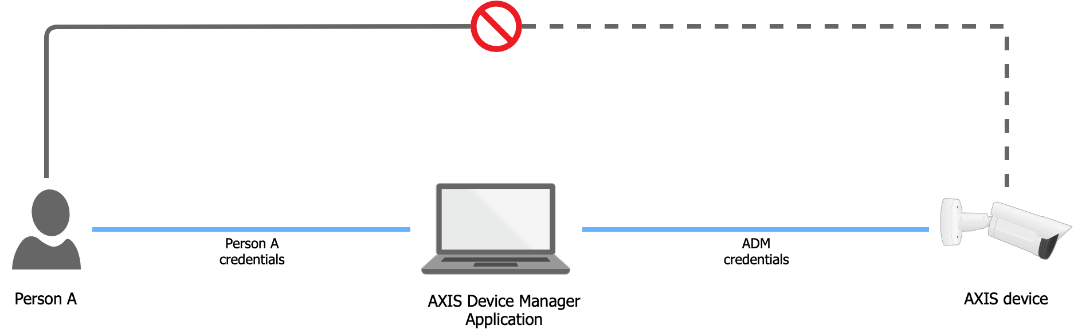
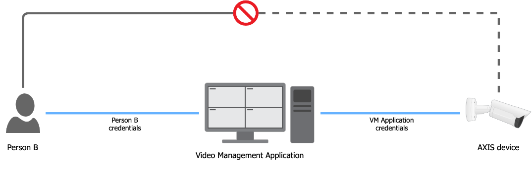
The diagrams below visualize the best practices of access management in the device.
| Scenario A |
 |
|
| Scenario B |
 |
|
The device is exposed to the following risks when using user accounts in the device:
Unauthorized personel accessing devices
Wrong level of authorization in different devices
Re-use of user account credentials prevents audit traceability
Poor scalability with increasing number of devices
Different sites and organizations can have different policies, including password policies, which the system should be set up to accommodate. Typically, each application should have its own credentials for devices. If the password is reused in devices, Axis recommends changing the password frequently.
Authorization and account privileges
Axis devices support the roles Administrator, Operator, and Viewer, with different authorization levels. Axis recommends setting up an administrator account for management applications that have access to the devices. This account should be unique for each application and should not be shared. Ideally, the password for this account should be generated by the management application itself and should remain unknown to individuals.
If direct access to devices is needed
Some configurations may not be natively supported by the application and may need to be done through the devices web interface. Axis recommends to access the Axis device web interface through the seamless access provided by Axis' device management applications.
If there are strong reasons for allowing direct access to devices, Axis recommends using temporary service account impersonalization with limited access. A new service account should be created on the device with the appropriate role for what needs to be done. Once direct access is no longer required, the service account should be deleted.
Device access
Legacy access procedure (default user with default password)
Historically, Axis devices in their factory default state have had their VAPIX and ONVIF interfaces activated for out-of-the-box access on the network for clients connecting to them. This meant that a client, such as an application or video management system, could access the Axis network device via anonymous ONVIF calls as well as the default VAPIX user "root" with the default password "pass", prior to having configured anything on the Axis network device itself.
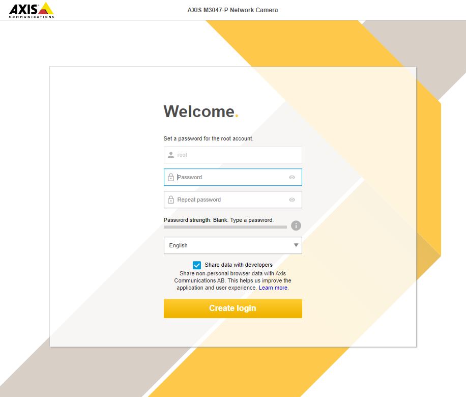
Updated access procedure (default user with no default password)
The VAPIX and ONVIF interfaces have been disabled and the "root" VAPIX user password is no longer set in the factory default state. This means that it’s no longer possible for a client to access or configure the device out-of-the-box without setting a password for the VAPIX user "root".
The update access procedure has been implemented in the following AXIS OS releases:
Version 5.51.6
Version 6.50.4 (2016 LTS)
Version 8.40.3 (2018 LTS)
Version 9.40.1 and higher
Furthermore, the updated procedure has been rolled out on individual product releases that are outside the scope of the above platform releases, such as:
1.65.x
1.8x.x
5.75.x
6.53.x
6.55.x
7.15.x
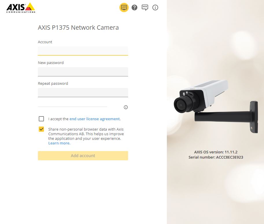
Modern access procedure (no default user)
As of AXIS OS 11.6 and higher, the default VAPIX user "root" has been removed from the Axis device in its factory default state and it is now possible to instead create a custom VAPIX user in the factory default state.
Anonymous interface calls
Interface calls that do not require authentication (=anonymous) are still allowed for device identification purposes. An Axis device can be identified in its factory default state by its HTTP response header which is set to "AXIS-Setup:vapix" when an VAPIX or ONVIF API call is made, as illustrated below:
HTTP/1.1 401
Unauthorized Date: Thu, 19 Sep 2019 18:15:20 GMT
Server: Apache/2.4.39 (Unix) OpenSSL/1.1.1c
Axis-Setup: vapix
Activate VAPIX and/or ONVIF interfaces
The VAPIX and/or ONVIF interfaces in the Axis device can be activated using the following methods:
The VAPIX interface is activated when an initial VAPIX user password is set, either via VAPIX System Settings API, as described in the VAPIX library or by using the Axis device's web interface during the installation process.
The ONVIF interface can only be activated after the VAPIX interface has been activated. After that, the ONVIF interface can be activated by creating an ONVIF user via the device's web interface.
AXIS OS version
Web interface configuration path
< 7.10
Setup > System Options > Security > ONVIF
≥ 7.10
Settings > System > ONVIF
≥ 10.9
System > ONVIF
In addition, an ONVIF user can also be created using the ONVIF Profile S specifications. An example of the API call to create an ONVIF user is described below:
POST /vapix/services HTTP/1.1
<SOAP-ENV:Envelope xmlns:wsdl="http://schemas.xmlsoap.org/wsdl/"
xmlns:xs="http://www.w3.org/2001/XMLSchema"
xmlns:tds="http://www.onvif.org/ver10/device/wsdl"
xmlns:xsi="http://www.w3.org/2001/XMLSchema-instance"
xmlns:xsd="http://www.w3.org/2001/XMLSchema"
xmlns:onvif="http://www.onvif.org/ver10/schema"
xmlns:tt="http://www.onvif.org/ver10/schema"
xmlns:SOAP-ENV="http://www.w3.org/2003/05/soap-envelope">
<SOAP-ENV:Body>
<tds:CreateUsers xmlns="http://www.onvif.org/ver10/device/wsdl">
<User>
<tt:Username>admintt:Username>admin>
<tt:Password>admintt:Password>admin>
<tt:UserLevel>Administratortt:UserLevel>Administrator>
</User>
</tds:CreateUsers>
</SOAP-ENV:Body></SOAP-ENV:Envelope>
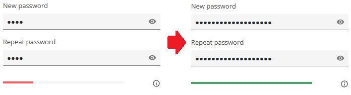
Password strength indicator
Axis devices with AXIS OS 7.20 or higher include a password strength indicator, which is visible when creating or modifying a user account password through the web interface. It indicates if the strength of the chosen password is considered weak, medium or strong and also provides advice on how to strengthen it. The indicator follows the ZXCVBN algorithm developed by Dropbox. More information about setting the device password is available in the AXIS OS Hardening Guide.
I forgot my password, what to do?
You cannot recover lost or forgotten access credentials to an Axis device. The device needs to be reset to its factory default settings in order to reconfigure it with new access credentials.
Device access logging
Successful and unsuccessful login attempts are logged in the Axis device’s log system depending on the network protocol in use. At all times, it is recommend to configure a remote syslog server to which the Axis device can send its syslogs. This ensures that logs are retained for a specified period and don’t get erased after e.g. a device reboot or factory default.
SSH
Successful | [ INFO ] sshd[17583]: Accepted password for root from 10.197.252.38 port 41988 ssh2 |
Unsuccessful | [ INFO ] sshd[17727]: Failed password for root from 10.197.252.38 port 41994 ssh2 |
| After 5 failed attempts | [ ERR ] sshd[17727]: error: maximum authentication attempts exceeded for root from 10.197.252.38 port 41994 ssh2 [preauth][ INFO ] sshd[17727]: Disconnecting authenticating user root 10.197.252.38 port 41994: Too many authentication failures [preauth] |
FTP
Successful | [ INFO ] vftpd[18263]: Accepted request from 172.27.0.3 50333[ INFO ] vftpd[18263]: User root logged in. |
Unsuccessful | [ INFO ] vftpd[18163]: Accepted request from 172.27.0.3 64936[ INFO ] vftpd[18163]: Incorrect username/password. User access from 172.27.0.3 denied.[ INFO ] vftpd[18163]: Client 172.27.0.3 disconnected. |
RTSP protocol
Successful | [ NOTICE ] monolith: RTSP UNKNOWN session h4fIznyTZNy16tLt created from 172.25.155.83 |
Unsuccessful | [ WARNING ] monolith: Rtsp login failed from 172.25.155.83 |
HTTP(S) protocol
Successful* | [ NOTICE ] httpd[22254]: root from 10.197.240.111 /axis-cgi/login.cgi GET 200 |
Unsuccessful** | [ NOTICE ] httpd[21459]: root from 10.197.240.111 failed to access /axis-cgi/usergroup.cgi.Password mismatch |
*Requires the Access Log parameter to be enabled from Plain Config > System.
**Only login attempts using the correct username will be logged. This log message is only available from AXIS OS 10.4 and later.
IP filtering***
Unsuccessful | IP_FILTER: IN=eth0 OUT= MAC=ff:ff:ff:ff:ff:ff:30:9c:23:e2:48:b5:08:00 SRC=172.25.201.50 DST=172.25.201.255 LEN=78 TOS=0x00 PREC=0x00 TTL=128 ID=60428 PROTO=UDP SPT=137 DPT=137 LEN=58IP_FILTER: IN=eth0 OUT= MAC=ff:ff:ff:ff:ff:ff:30:9c:23:e2:48:b5:08:00 SRC=172.25.201.50 DST=172.25.201.255 LEN=78 TOS=0x00 PREC=0x00 TTL=128 ID=60429 PROTO=UDP SPT=137 DPT=137 LEN=58 |
***IP filtering in Axis devices is network layer-2 Linux Kernel functionality that blocks network packages depending on the configured rules. No authentication is performed if an unsuited source IP address is trying to access the Axis device since the network transmission is blocked right at the layer-2 network while authentication is performed on higher level application layers. Corresponding logs of the IP filtering can be created when the VAPIX parameter is enabled in Plain Config > Network in the IP Filtering section.
PreventDosAttack****
Unsuccessful | AXIS OS 11.5 and lower | [ WARNING ] httpd[22254]: [evasive20:warn] [pid 22254:tid 1428104112] [client 172.25.201.116:42058] Blacklisting address 172.25.201.116: possible DoS attack. |
Unsuccessful | AXIS OS 11.6 and higher | [ WARNING ] httpd[22254]: [evasive20:warn] [pid 22254:tid 1428104112] [client 172.25.201.116:42058] Blocklisting address 172.25.201.116: possible DoS attack. |
****PreventDosAttack can be enabled from Plain Config > System and will only log unsuccessful login attempts and log when a source IP address is blocked.
User management configuration
As of AXIS OS 10.9, user configuration-related changes are logged and can be sent to a remote syslog server. In AXIS OS, VAPIX and ONVIF users are separated by having their own management interfaces and access rights. This table illustrates which log messages to expect when certain changes to the user management configuration are made:
| API interface | Use case | Log message |
| VAPIX | Add user | VAPIX user andre from IP-address 10.197.240.104 created VAPIX user benjamin with role Administrator |
| VAPIX | Change access group | VAPIX user susanna from IP-address 10.197.240.104 changed VAPIX user linda role from Administrator to Operator |
| VAPIX | Change password | VAPIX user root from IP-address 10.197.240.104 changed VAPIX user thomas password |
| VAPIX | Delete user | VAPIX user root from IP-address 10.197.240.104 deleted VAPIX user sebastian with role Operator |
| ONVIF | Add user | VAPIX user root from IP-address 10.197.240.104 created ONVIF user andre with role Administrator |
| ONVIF | Change access group | ONVIF user andre from IP-address 10.197.240.104 changed ONVIF user susanna role from Administrator to Operator |
| ONVIF | Change password | ONVIF user thomas from IP-address 10.197.240.104 changed ONVIF user andre password |
| ONVIF | Delete user | ONVIF user pernilla from IP-address 10.197.240.104 deleted ONVIF user sebastian with role Operator |
Audit log
Audit logs are used for cybersecurity-related purposes such as incident handling and helping to establish long-term monitoring of relevant events and actions. This feature requires AXIS OS 12.5 or later.
Important considerations and recommendations:
Audit logging is enabled automatically and cannot be turned off.
Audit logs cannot be removed, modified, or tampered with.
Audit logs remain available after a reboot or power cycle.
We recommend that you transfer audit logs to external systems for proper long-term storage, automated analysis, and notifications.
Audit logs are always saved on the Axis device, regardless of whether an external system is used. This serves as a failover mechanism in worst-case scenarios.
System architecture
There are several options and scenarios for using and consuming audit logs. AXIS OS audit is designed to integrate easily with various applications and systems.
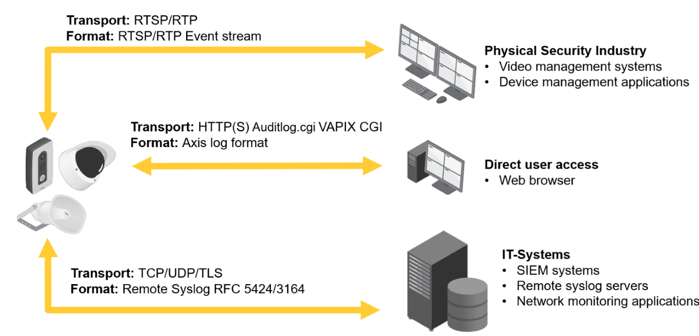
Direct user access
You can access the audit log through the Log section of the web interface, or by browsing to: https://ip-address/axis-cgi/admin/auditlog.cgi.
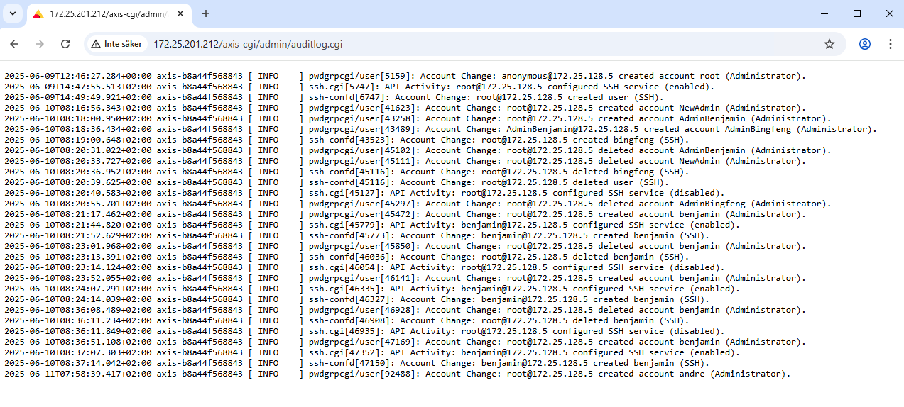
Applications can also use the auditlog.cgi
VAPIX CGI to download audit logs.
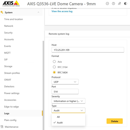
IT systems
Unlike regular device logs, audit logs are retained after the device is restarted. However, we recommend using the remote syslog functionality to enable centralized audit logging for monitoring and incident response based on relevant account activities and configuration changes on your Axis device. To enable audit logging through remote syslog, select Audit in the Remote system log settings
Audit log content
In general, the structure of most of our audit logs looks like this:
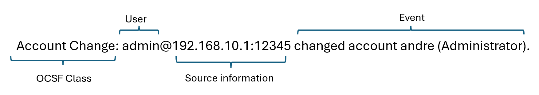
- OCSF Class: The audit log is categorized using Open Cybersecurity Schema Framework (OCSF) classes. Each OCSF class represents a specific type of event or data. The next section shows some examples.
User: who performed the action.
Source information: where the event came from, the source IP address and the port.
Event: what action was taken.
Not all examples are implemented in AXIS OS 12.5. New log messages and classes will be added in future updates.
OCSF Class: Authentication
Use case: Logs successful and failed authentication attempts, as well as logout events.
Authentication: admin@192.168.10.1:12345 Authentication failed (SSH).
Authentication: admin Logged out (SSH).
Authentication: admin@192.168.10.1:12345 Authentication successful (HTTP/S).
Authentication: admin@192.168.10.1:12345 Logged out (HTTP/S).
Authentication: admin@192.168.10.1:12345 Authentication successful (RTSP).
OCSF Class: Network Remediation Activity
Use case: Logs network security and firewall-related traffic information, primarily when incoming network connections are blocked.
Network Remediation Activity: Firewall blocked 192.168.10.1:80 from B8:A4:4F:28:1D:B4 (Rule 5)
OCSF Class: API Activity
Use case: Logs configuration changes such as parameter updates, ACAP installations, and AXIS OS upgrades.
API Activity: admin@192.168.10.1:12345 updated Network.DNSServer1 (192.168.0.110).
API Activity: admin@192.168.10.1:12345 updated Image.I0.Appearance.Compression (40).
API Activity: admin@192.168.10.1:12345 added ssh.v1.users ({"comment":"","password":"**Redacted**","username":"sshacount"}).
API Activity: admin@192.168.10.1:12345 started app: Axis Video Motion Detection 4 (vmd 4.5.14).
API Activity: admin@192.168.10.1:12345 updated shuttergain.setGain ({"source": 0,"property": "max","value": 65}).
OCSF Class: Account Change
Use case: Logs account-related configuration changes.
Account Change: admin@192.168.10.1:12345 changed account andre (Administrator).
Account Change: admin@192.168.10.1:12345 changed account andre (Password Update).
Account Change: admin@192.168.10.1:12345 created account test (SSH).
OCSF Class: Entity Management
Use case 1: Logs system-relevant events such as device restarts, factory resets, and similar actions.
Entity Management: Audit Log started.
Entity Management: Audit Log rotated (2025-09-10 11:09:15.981+02:00 - 2025-09-21 11:09:15.561+02:00 has been removed).
Entity Management: admin@192.168.10.1:12345 Upgrade started (12.31.32).
Entity Management: Upgrade completed (12.31.32).
Entity Management: admin@192.168.10.1:12345 Restart.
Entity Management: admin@192.168.10.1:12345 Factory default (hard).Entity Management: admin@192.168.10.1:12345 Factory default (soft).
Entity Management: admin@192.168.10.1:12345 Rollback (11.11.199).
Entity Management: admin@192.168.10.1:12345 Installed custom firmware certificate (axis-unlock-acap-devmode).
Use case 2: Logs relevant storage and recording events.
Entity Management: admin@192.168.10.1:1962 Exported recording (Recording_ID = 20251126_180156_770C_B8A44F28254E, After = 2025-11-26T17:02:54.171251Z, Before = 2025-11-26T17:10:38.000000Z, Disk_ID = Network share).
Entity Management: admin@192.168.10.1:19994 Deleted recording (Recording_ID = 20251126_171103_C634_B8A44F28254E, After = 2025-11-26T16:11:03.765374Z, Before = 2025-11-26T16:14:27.699085Z, Disk_ID = Network share).
Entity Management: admin@192.168.10.1:12345 Started recording (Recording_ID = 20250306_083730_4F14_B8A44F281DB4, Disk_ID = SD card).
OCSF Class: Network Activity
Use case: Logs video, audio, and metadata streaming events when clients connect to the device.
Network Activity: admin@192.168.10.1:1147 Requested JPEG image (Proto:HTTP,UserAgent:mozilla/5.0 (windows nt 10.0; win64; x64) applewebkit/537.36 (khtml, like gecko) chrome/142.0.0.0 safari/537.36).
Network Activity: admin@192.168.10.1:19526 Started streaming (Id:2,Proto:HTTP,Media:VIDEO,UserAgent:mozilla/5.0 (windows nt 10.0; win64; x64) applewebkit/537.36 (khtml, like gecko) chrome/142.0.0.0 safari/537.36).
Network Activity: Number of current active streams (1).
Network Activity: admin@192.168.10.1:19526 Stopped streaming (Id:2,Proto:HTTP,Media:VIDEO,UserAgent:mozilla/5.0 (windows nt 10.0; win64; x64) applewebkit/537.36 (khtml, like gecko) chrome/142.0.0.0 safari/537.36).
Network Activity: Number of current active streams (0).
Network Activity: Started streaming (Id:1,Proto:RTP/UDP,Media:VIDEO,Destination:239.241.34.89:50998).
OCSF Class: Base Event
Use case: Logs Remote Syslog audit test messages.
Base Event: This is an audit test message.
AXIS OS audit log is designed to record at least the latest 1,000 audit log events and to retain them subsequent to a system reboot or power cycle, but they are not retained following a system restore or a reset to factory default. The internal audit log mechanism conducts periodic reviews of the log files at 30 minute intervals. If the file size exceeds 300 KB, a new file is generated, with only the three most recent audit log files being preserved. Typically, the Axis device allocates 1 MB storage capacity for audit logging purposes. As illustrated in the preceding examples, the size of audit log events may vary depending on the specific event. Consequently, the maximum number of events that can be retained is inversely proportional to the size of the individual log records.
A typical log event is approximately 300–400 bytes in size, thereby enabling the device to retain approximately 2,600–3,300 events. However, for certain DeCaf API change logs, the size of each event may range from 500 to 600 bytes, thus reducing the device's log retention capacity to approximately 1,600–2,000 events. We recommend using a remote Syslog server to ensure that audit logs are securely transmitted off the local device, to reduce the risk of data loss due to limited local storage or device failure.
Authentication schemes
AXIS OS 11.11 and later versions support multiple authentication scheme configuration through virtual hosts. This enables hybrid setups where Basic, Digest or OAuth 2.0 OpenID Connect authentication schemes can be used for centralized Identity and Access Management (IAM) with Active Directory Federation Services (ADFS) and other Identity Provider (IdP) solutions.
Axis devices support the following authentication schemes through HTTP/HTTPS:
Basic
Digest
OAuth 2.0 OpenID Connect Authorization Code Flow
OAuth 2.0 OpenID Connect Client Credentials Grant
As of AXIS OS 12.8 it is possible to disable basic and/or digest authentication and only allow OAuth 2.0 authentication schemes.
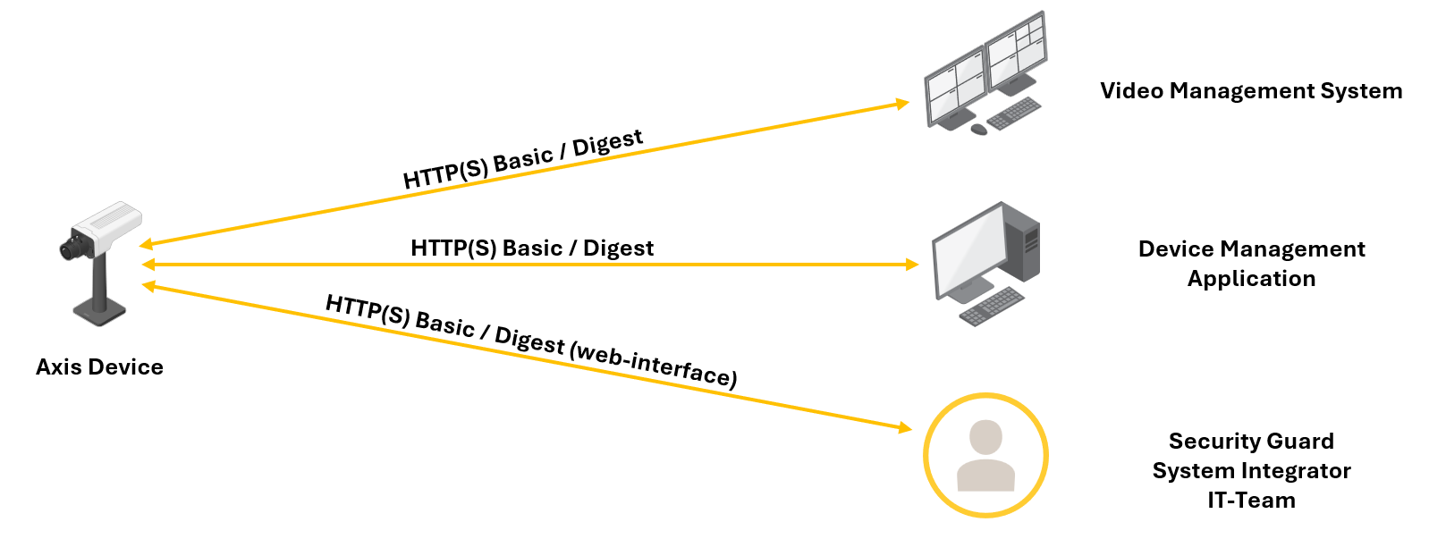
Legacy setup with HTTP(S) Basic/Digest only
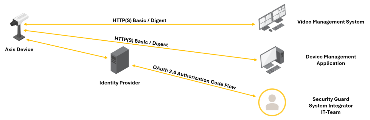
Hybrid setup with HTTP(S) Basic/Digest and OAuth 2.0 Authorization Code Flow
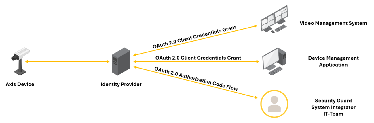
Fully adapted setup with OAuth 2.0 Client Credential Grant and OAuth 2.0 Authorization Code Flow
Configuration example with different authentication schemes on different ports
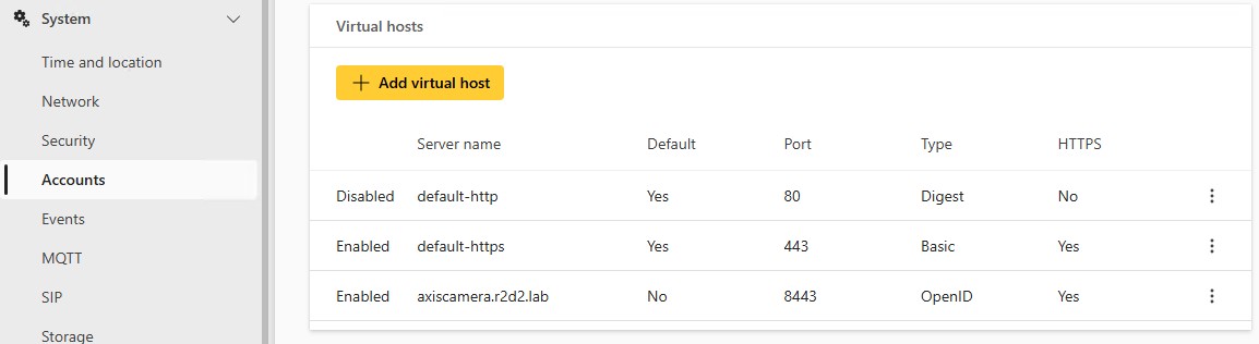
Name | Port | Authentication scheme | Comment |
default-http | 80 | HTTP Digest | Disabled in this example |
default-https | 443 | HTTP Basic | |
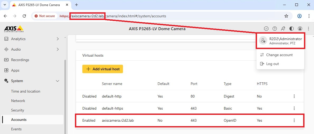
axiscamera.r2d2.lab | 8443 | OpenID |
|
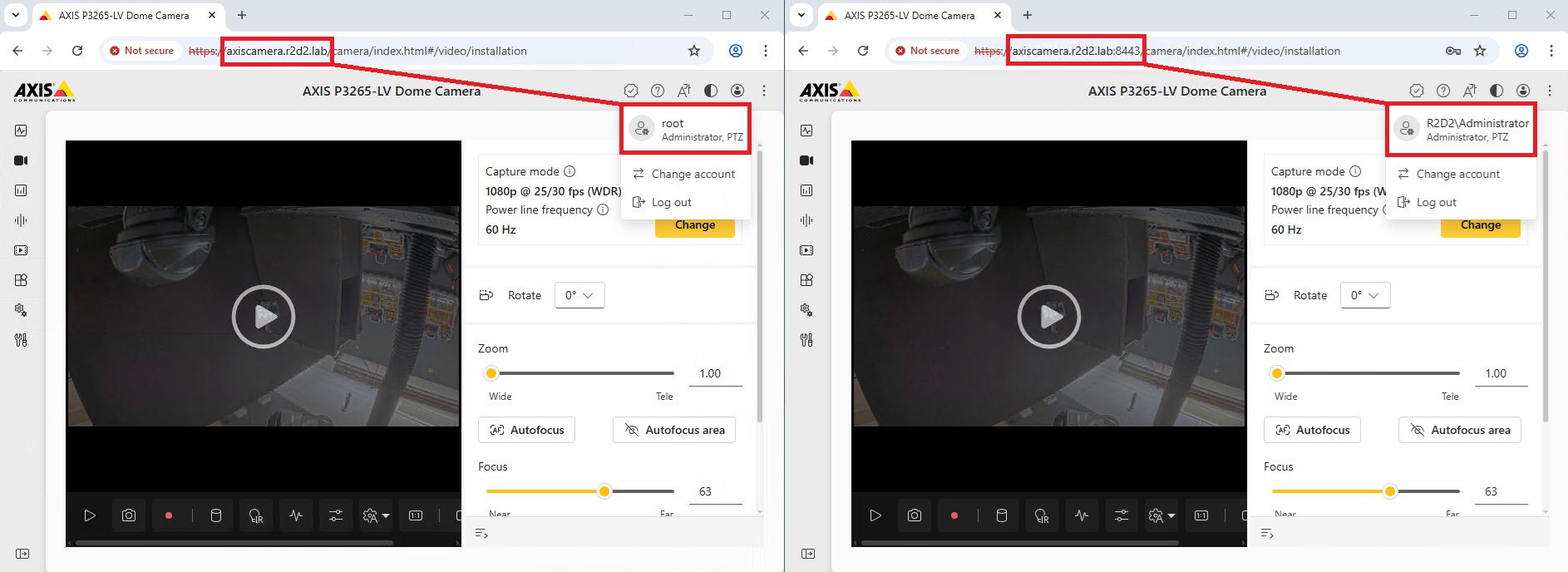
The authentication scheme the device accepts differs depending on which of the ports you attempt to access the Axis device on.
| Address | Authentication scheme |
| https://axiscamera.r2d2.lab:443 | HTTPS Basic |
| https://axiscamera.r2d2.lab:8443 | OAuth 2.0 OpenID Connect Authorization Code Flow |
Configuration example with different authentication schemes on the same port
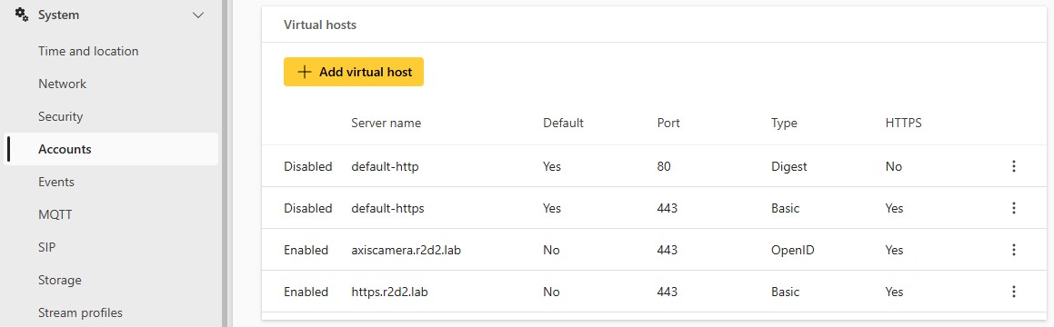
Name | Port | Authentication scheme | Comment |
default-http | 80 | HTTP Digest | Disabled in this example |
default-https | 443 | HTTPS Basic | Disabled in this example |
axiscamera.r2d2.lab | 443 | OpenID | |
https.r2d2.lab | 443 | HTTPS Basic |
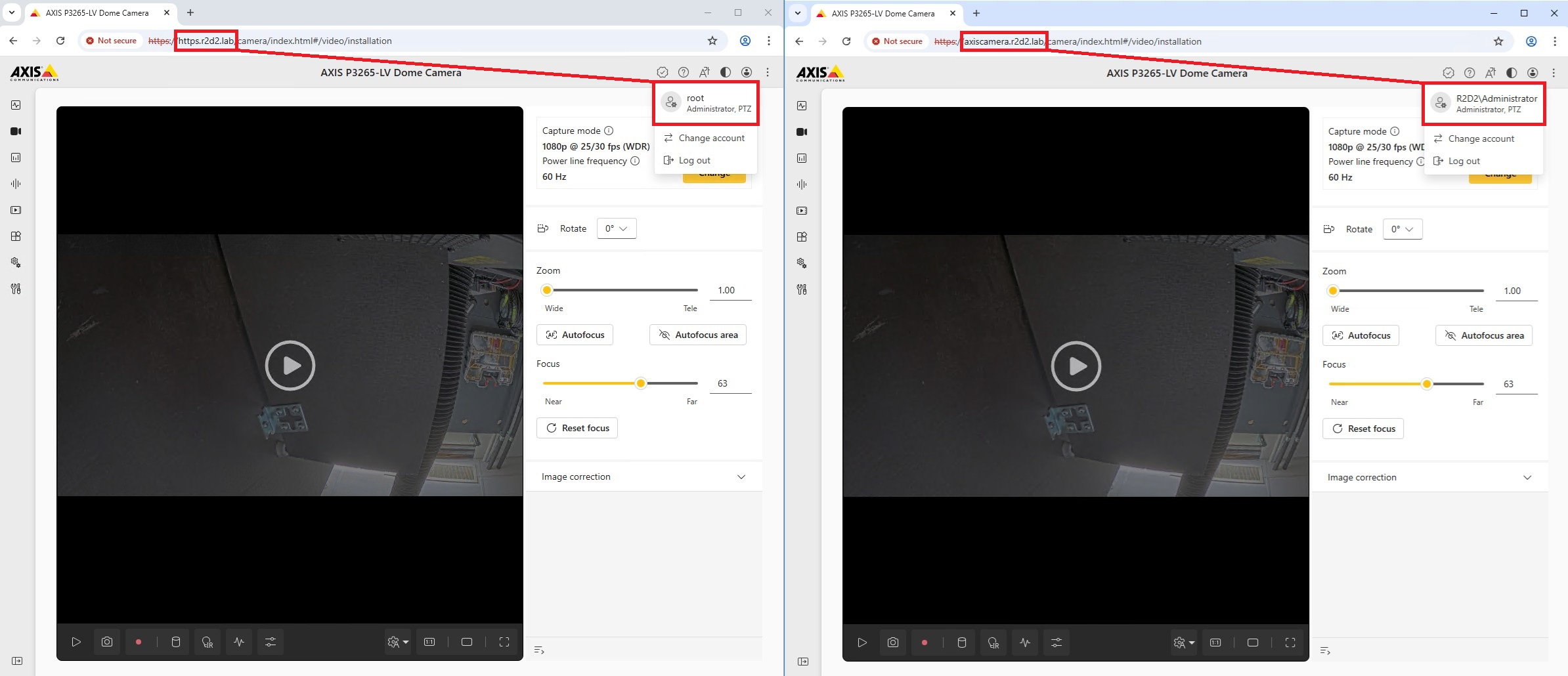
Because of the way virtual hosts work, the configured name will be used as the hostname to differentiate between the above two authentication schemes. In this example, we’ve chosen https & OpenID. The authentication scheme the device accepts differs depending on which of the two hostnames you use to access the device.
| Address | Authentication scheme |
https://https.r2d2.lab:443 | HTTPS Basic |
https://axiscamera.r2d2.lab:443 | OAuth 2.0 OpenID Connect Authorization Code Flow |
Note that this setup might require updates in your DNS infrastructure to ensure that both hostnames are correctly accessible and resolved.
Configuration example with only the OpenID authentication scheme enabled
Name | Port | Authentication scheme | Comment |
default-http | 80 | HTTP Digest | Disabled in this example |
default-https | 443 | HTTPS Basic | Disabled in this example |
axiscamera.r2d2.lab | 443 | OpenID |
|
Brute force delay protection
AXIS OS 7.30 or higher
Axis devices running AXIS OS 7.30 and higher can be configured to automatically block HTTP/HTTPS requests coming from a client in the network (IP address). For a certain amount of time, a defined number of authentications will fail. This feature can help protect the Axis device against brute-force attacks, or against network clients that unintentionally behave in a similar manner. The brute force delay protection can be configured in Plain config > System.
AXIS OS 11.5 or higher
With AXIS OS 11.5 or higher, brute force delay protection is enabled by default using configuration example 1 below.
Generally the lower the allowed page/site count is, the more secure the protection. Implementing brute force delay protection significantly increases the time required to guess a password, making brute-force attacks far less effective. Some indications can be found below. Note that configuring a strong password is always recommend.
| Condition | Total brute force time without delay protection enabled - 720 requests/sec* | Total brute force time configuration example 1 | Total brute force time configuration example 2 |
| 4 characters with lower case letters only | +- 11 minutes | +- 6 hours | +- 13 hours |
| 4 characters with upper and lower case letters, 0 to 9 | +- 6 hours | +- 205 hours | +- 410 hours |
| 5 characters with lower case letters only | +- 5 hours | +- 7 days | +- 14 days |
| 5 characters with upper and lower case letters, 0 to 9 | +- 14 days (+- 2 weeks) | +- 1.5 years | +- 3 years |
*Actual rate may vary and depends on product performance.
Trying to access the web interface from a network client previously identified as a threat would result in a HTTP 403 Forbidden response.
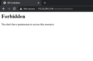
If this happens, the Axis device will also log the following in the system log:
AXIS OS 11.5 and lower | 2021-08-16T12:17:35.119+02:00 axis-accc8ed910b9 [ WARNING ] httpd[592]: [evasive20:warn] [client 172.25.201.116:41972] Blacklisting address 172.25.201.116: possible DoS attack. |
AXIS OS 11.6 and higher | 2021-08-16T12:17:35.119+02:00 axis-accc8ed910b9 [ WARNING ] httpd[592]: [evasive20:warn] [client 172.25.201.116:41972] Blocklisting address 172.25.201.116: possible DoS attack. |
Parameter description
| Parameter | Description |
| DOSBlockingPeriod | The blocking period is the amount of time (in seconds) a client will be blocked if added to the blocking list. During this period, all subsequent requests from the client will result in a 403 (Forbidden). |
| DOSPageCount | This is the threshold for the number of requests for the same page (or URI) per page interval. Once the threshold for that interval has been exceeded, the IP address of the client will be added to the blocking list. A page is considered to be, for example, http://ip-address/system/plainconfig. |
| DOSPageInterval | The interval for the page count threshold; defaults to 1 second intervals. |
| DOSSiteCount | This is the threshold for the total number of requests for any object by the same client on the same listener per site interval. Once the threshold for that interval has been exceeded, the IP address of the client will be added to the blocking list. A site is considered to be, for example, http://ip-address/ |
| DOSSiteInterval | The interval for the site count threshold; defaults to 1 second intervals. |
Configuration examples
Example 1: After 20 failed login attempts within one second, the client IP address is blocked for 10 seconds. This is the default configuration and offers flexible security where – to some extent – failed login attempts from well-known authorized clients are taken into account.
Example 2: After 10 failed login attempts within one second, the client IP address is blocked for 10 seconds. This configuration is recommended for very strict and high security systems where even a few failed login attempts will block a client.
Setting | Example 1 | Example 2 |
Activate Password Throttling | On | On |
DoS Blocking Period(sec) | 10 | 10 |
DoS Page Count(req/DoSPageInterval) | 20 | 10 |
DoS Page Interval(sec) | 1 | 1 |
DOS Site Count(req/DoSSiteInterval) | 20 | 10 |
DoS Site Interval(sec) | 1 | 1 |
Host-based firewall
Axis devices running AXIS OS 11.9 and higher have the host-based firewall feature, which replaces the legacy IP Address Filter. The host-based firewall regulates network traffic to Axis devices, adding an additional security layer to protect against unauthorized access and attacks.
The firewall uses policies and rules to control incoming traffic, and defines which packets (or frames) can pass through and which should be blocked. Below is an overview of the specific criteria supported based on the AXIS OS version installed on your device:
| Criteria | Available with version |
| IPv4/IPv6 address | 11.9 |
| TCP/UDP port | |
| IPv4/IPv6 address range | 12.5 |
| TCP/UDP port range | |
| MAC address | |
| Packet Type (unicast, multicast, broadcast) | |
| Packet rate limiting |
Policy: defines how the firewall should handle network traffic when it matches specific criteria in a rule:
Deny: discards the packets.
Allow: allows packets to pass through.
Default policy: defines how the firewall should handle packets that don’t match any criteria specified by the user:
Deny: discards all incoming traffic unless specifically allowed by a rule.
Allow: allows all incoming traffic unless specifically blocked by a rule.
Firewall rules execute from top to bottom, so their order matters. For example, you may want to allow clients to connect to the device via ports 80 and 443, except, for example, client 192.168.0.200. However, if the rules are in the wrong order, 192.168.0.200 could still connect to the device via ports 80 or 443. To prevent this, move the last rule (denying client 192.168.0.200) to the top.
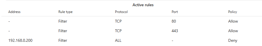
Plan your firewall rules carefully, as faulty configuration may block access to your devices. The host-based firewall includes a test feature that lets you test new rules for a set period before making them permanent.
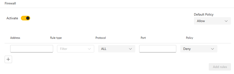
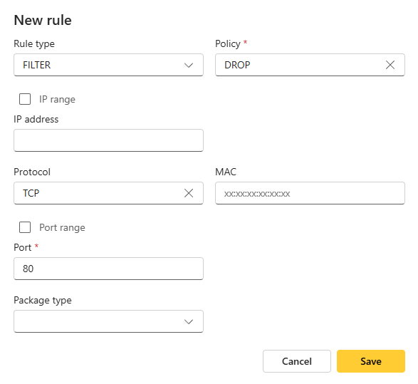
In the example below, we’ve added two rules to block clients from connecting to the device via HTTP (TCP 80) and SSH (TCP 22).
Configuration example
From AXIS OS 11.9 to 12.4:
Add the rules.

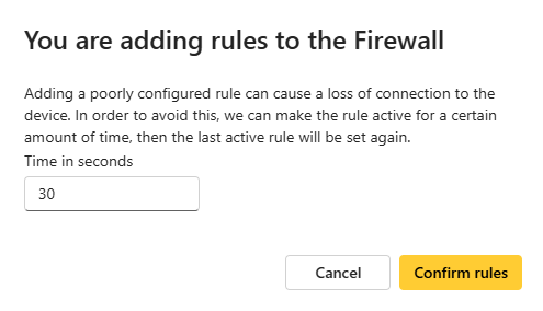
Set the timer to test the rules.
- Once you have edited the rules, click Add rule. A new window appears, prompting you to test the new rules. You can set a time (x seconds) to test the rules. To activate the rules immediately, you can set the timer to 0 to skip the test process.
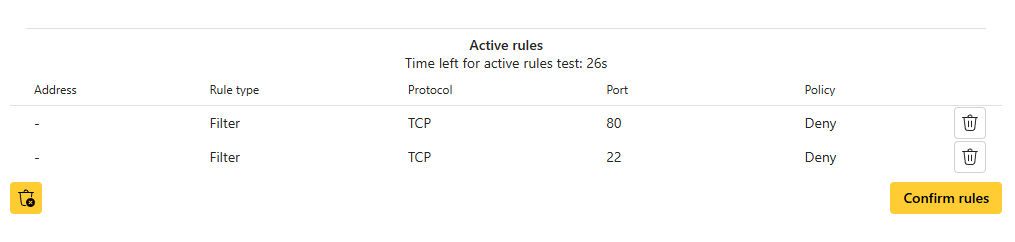
Test the rules during the timer period.
- The two rules are now temporarily active during the timer period. Verify that the rules work as expected. Once the timer period ends, the rules will appear under Pending rules.
Confirm the rules.
- If everything works as expected, click Confirm rules under Pending rules to activate them.
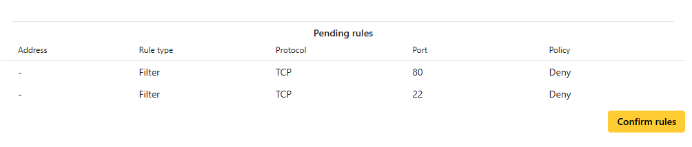
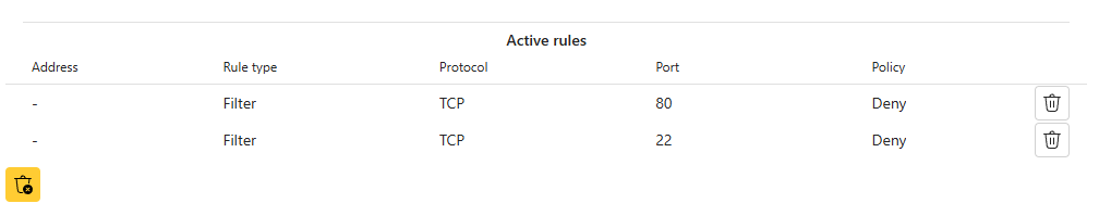
- Once confirmed, the rules will appear under Active rules.
AXIS OS 12.5 and higher:
Add the rules.
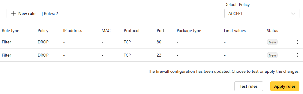
Test the rules.
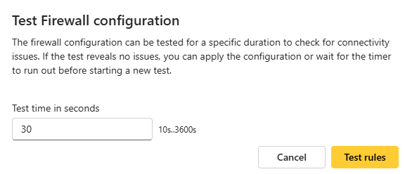
Click Test rules. A new window appears, prompting you to test the new rules. You can set a time (x seconds) to test the rules. To activate the rules immediately, you can set the timer to 0 to skip the test process.
Apply the rules.
Once the test timer period ends, the rules’ status will show as Tested. If everything works as expected, click Apply rules. Otherwise, click Rollback to return the firewall to its previous state before you tested the rules.
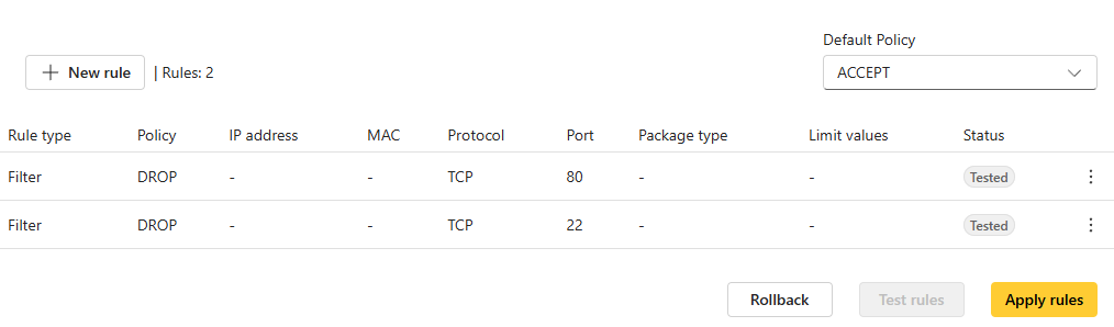
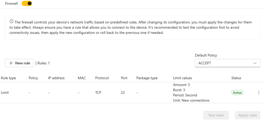
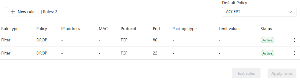
In the screenshot below, the rules have been applied and their status has changed to Active.
New connection rate limiting feature
The new connection rate limiting feature tracks new connections to the device and matches them at a limited rate using a token bucket filter. This feature is mainly used to avoid various denial-of-service attacks (DoS).
The rule type should be set to LIMIT to create a connection limit.
Amount: Maximum average matching rate: specified as a number, with an optional '/second', '/minute', '/hour', or '/day' suffix. This specifies the rate at which the bucket refills with tokens. 3/second means 3 tokens every second.
Burst: The maximum initial number of connections to match. This specifies the maximum number of tokens the bucket can hold. This number is refreshed based on the Amount value until the bucket reaches its upper limit.
There is also a user-configurable default rate limiting rule for new SSH connections.
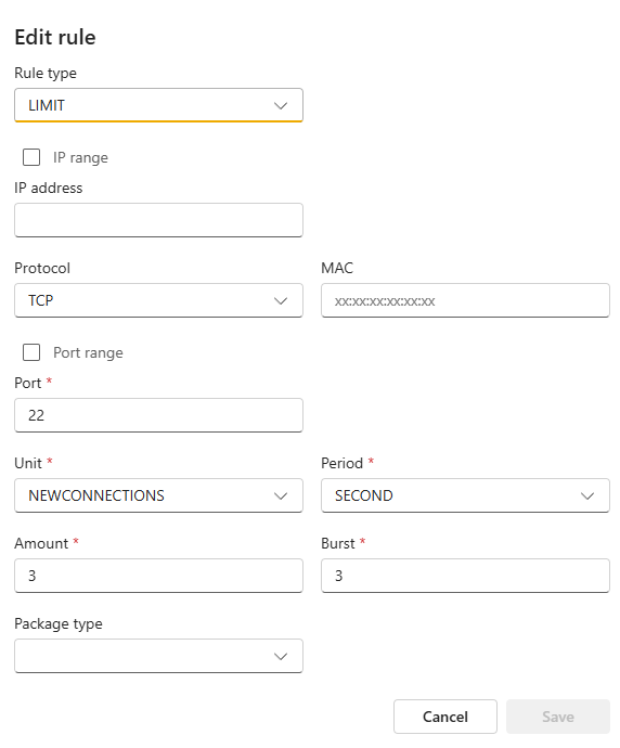
In the above example, Burst is set to 3, and Amount is set to 3/second by default. The first 3 SSH connections will be accepted. After this happens, it will take around 333ms before a new SSH connection is accepted. Meanwhile, if no SSH connection is matched every 333ms, one burst will be added back to the initial bucket. If no SSH connection occurs for 1 second, the burst will be fully recharged.
Product-specific rules
When you connect certain accessories to a product, the device automatically creates firewall rules tailored to them. These accessories rely on specific ports to communicate with the device. If the firewall blocks these ports, the accessories might not function as expected. The product-specific rules will overrule the user-configured rules. Note that these rules are not configurable by the user and cannot be seen through the device's web interface. You can only find these rules in the server report .
Limitations
The firewall doesn't currently support connection tracking. In the example NTP, the NTP client sends requests to servers on UDP port 123. The server then responds from source port 123 to a high ephemeral port on the client. Since the firewall doesn't support connection tracking or stateful tracking, it doesn't monitor the initial outgoing traffic from the device to the NTP server. As a result, the firewall drops the NTP server's response unless you explicitly allow the NTP server's IP address.
Signed OS
About signed OS
Signed OS is a feature that ensures that only verified and trusted device software is uploaded to and used in Axis devices. In this section you can read about technical details that will ensure that the correct update and downgrade paths are selected. For general information about the signed OS feature, see the Cybersecurity features in Axis products white paper.
Axis started to sign its device software as of AXIS OS 8.30.1. Until the release of AXIS OS 9.20.1, devices would still accept both unsigned and signed software, for backwards compatibility. As of AXIS OS 9.20.1, signed OS was fully activated and Axis devices would then only accept software signed by Axis. This means it is not possible to perform a rollback or downgrade to a version below AXIS OS 8.30.1, which is the version in which Axis initially started to sign device software.
Question: Can I downgrade my device from AXIS OS 9.10.1 to AXIS OS 8.40 LTS?
Answer: Yes, this will work.Question: My VMS requires me to maintain backwards compatibility. Can I downgrade my device from AXIS OS 9.20.1 to AXIS OS 8.20.1 or lower?
Answer: This downgrade will fail. The device will reject the unsigned version and will continue to run AXIS 9.20.1. You can however, do this downgrade in two steps, using AXIS OS 8.30.1 as a gateway. First downgrade from 9.20.1 to 8.30.1, and then from 8.30.1 to 8.20.1 or lower. Note that Axis does not generally encourage downgrades to older, unsupported AXIS OS versions.
Signed OS key lifecycle
Signature key pairs are generated on a dedicated offline key generation device. After generation, the private key is encrypted with two different asymmetric keys. One for secure import into a cluster of Thales Luna HSMs, and another for long-term offline backup outside the HSM at two separate secure locations.
The private key is provisioned into the HSM using an administrative role of the HSM that requires M of N authentication. At no point is the private key exposed in plain text during the import.
When Axis signs an AXIS OS image with said key, the signing request is processed by an application server that guards access to the HSM and which audits any use of the signing key. The application server can only be accessed from inside the Axis network and requires a signing-authorized account.
Revocation of an AXIS OS signing key entails issuing a bootloader update for all Axis devices using that key. As part of the update, the device’s anti-rollback mechanism is updated to block older bootloaders that still accept the revoked AXIS OS signing keys. Secure destruction of the signing keys requires physical destruction of the master backup key that exists in two copies.
Troubleshooting
How can you identify that an upgrade failed because of an unsigned OS? If a user tries to upload an unsigned version, one of the following messages is displayed in the device’s log files:
[ERR] fwmgr: Unknown firmware domain
[ERR] fwmgr: Image has no signature.
[ERR] fwmgr: No custom firmware certificate for camera group 'xxx'.
Signed ACAP applications
Axis takes proactive steps to implement ACAP application signing, aligning with industry best practices for secure software delivery. Additionally, it anticipates potential future enforcement through legislation, including the E.U. Cybersecurity Resilience Act, E.U. Radio Equipment Directive, and Executive Order 14028. Therefore, starting from AXIS OS 12.0 customers will only be able to install signed ACAP applications on Axis devices by default. Installation of unsigned ACAP applications will be possible only and only if a device is actively configured to accept unsigned ACAP applications. Configuring a device to accept unsigned ACAP applications will lower the device’s security, but it can be useful during development or if you develop and run your own ACAP application. Running unsigned ACAP applications is not recommended.
What are the benefits for end customers?
A signed ACAP indicates that Axis has a TIP-relationship with the partner who has developed the ACAP. By inspecting the ACAP, the end customer can see who the TIP-partner is. The partner name under the vendor tag is equivalent to the company name in Axis CRM records. Therefore, the signing process ensures the validation of the partner, traceability and accountability. This process enables the end customers to validate their ACAP applications.
What are the benefits in terms of cybersecurity?
The signing process ensures that the ACAP will only require Axis-approved access-rights and privileges when running on the Axis device. An ACAP that went through the signing process, will only run with limited, approved access rights on an Axis device. Furthermore, by signing the ACAP application, it is ensured that the content of the application is not tampered with from release to installation, hence it enables the secure software delivery.
Is Axis vetting the software quality, secure development practices or performing QA-testing on Signed ACAPs?
No, Axis does not take any responsibility for whether a TIP-partner ACAP that went through the signing process is QA-tested, or has been developed according to industry best-practices secure development processes. This responsibility lies entirely on the TIP-partner that is providing an ACAP application.
Who do we allow to have their ACAPs signed?
Only TIP partners are allowed to do so. This indicates that Axis has conducted a vetting process for its partners.
Will Axis provide ACAP signing capabilities for non-TIP partners as well?
For non-TIP partners that require signing capabilities, we will also perform a vetting process. Please use this link to request access.
How does the ACAP signing technically work?
During the ACAP application signing process, a cryptographic signature is added at the end of the application package. The signature is verified by the Axis device when installing the ACAP application as part of the overall secure software delivery architecture.
When will Axis enforce mandatory ACAP signing?
In alignment with secure software delivery practices, Axis will accept only and only Signed ACAP applications without the possibility to disable this security control on its devices. Axis aims to achieve this in the next generation of the AXIS OS operating system, which is planned to be AXIS OS 13.0 in H2 2026 and onwards.
Cryptographic support
A secure keystore is generally referred to as a dedicated hardware crypto computing module that offers protection of cryptographic operations, certificates, and keys. Axis products that support AXIS Edge Vault feature up to two secure keystores with corresponding security certification, either Common Criteria CC EAL6+ and/or CC EAL4+ / FIPS 140-2 level 2 certification according to the Federal Information Processing Standard, which could be a regulatory requirement for certain customers and use cases. Both secure keystores offer the same level of protection in terms of cryptographic operations, certificates, and keys. Additionally, some system-on-chips include a so-called Trusted Execution Environment (TEE). Depending on the installation requirements, the TEE might be a good choice due to lower latency for cryptographic operations.
The table below provides an overview of the cryptographic features of keystores found in Axis devices.
Cryptographic feature | Trusted Platform Module 2.0 (CC EAL4+, FIPS 140-2 level 2) | Secure element (CC EAL6+, FIPS 140-3 level 3) | Trusted Execution Environment (SoC TEE) | Software(1) |
Dedicated hardware protection of cryptographic operations, certificates and keys | ✓ | ✓ | ✓ | |
Strongest security | ✓ | ✓ | ||
Fastest performance | ✓ | ✓ | ||
Recommended for long-lived keys/certificate | ✓ | ✓ | ||
Recommended for short-lived keys/certificates | ✓ | ✓ | ||
X.509 certificates in format .PEM, .DER, .CER and .CRT with PKCS#1 formatted private keys | ✓ | ✓ | ✓ | ✓ |
PKCS#12 certificate/private key container in .p12 or .pfx format(2) | ✓ | ✓ | ✓ | ✓ |
RSA-cryptographic support | ✓ | ✓ | ✓ | ✓ |
| ECC-cryptographic support | ✓(3) | ✓(4) | ✓(4) | ✓(4) |
Hash algorithms SHA-224/256/384/512 | SHA-224/256 | SHA-224/256/384/512 | SHA-224/256/384/512 | SHA-224/256/384/512 |
RSA-crypto private key size uploadable | 2048 | 4096 | 4096 | 4096 |
ECC-crypto private key size uploadable | ECC NIST P-256 | ECC NIST P-256, ECC NIST P-384, ECC NIST P-521 | ECC NIST P-256, ECC NIST P-384, ECC NIST P-521 | ECC NIST P-256, ECC NIST P-384, ECC NIST P-521 |
RSA-crypto private key size uploadable | 2048 | 2048 4096 | 2048 3072 4096 | |
RSA-crypto private key size for self-signed certificate or certificate signing request(5) | 2048 | 4096 | 4096 | 4096 |
ECC-crypto private key size for self-signed certificate or certificate signing request(6) | ECC NIST P-256 | ECC NIST P-256, ECC NIST P-384, ECC NIST P-521 | ECC NIST P-256, ECC NIST P-384, ECC NIST P-521 | ECC NIST P-256, ECC NIST P-384, ECC NIST P-521 |
Legacy for products without any hardware protected secure keystore.
Support from AXIS OS 5.50 and higher, Max size of .PFX and .P12 certificate/private key container are limited to 102400 bytes except for devices running AXIS OS 9.20 and lower where only a maximum file size of 10240 bytes is supported.
The support for ECC was added in AXIS OS 10.10 excluding the following products which need to receive an software update manually: HWID 79C: AXIS Q3527-LVE, HWID 7DA: AXIS Q6074, HWID 7D9: AXIS Q6074-E, HWID 7B1: AXIS Q6075, HWID 7B0: AXIS Q6075-E, HWID 7B2: AXIS Q6075-C, HWID 7B3: AXIS Q6075-S, HWID 7FA: AXIS Q6075-SE and HWID 7C7: AXIS Q9216-SLV.
ECC cryptography support for Axis devices without TPM module has been added from AXIS OS 10.1 and higher.
Max key bit size of private key generated by the Axis device when creating a self-signed certificate (SSC) or issuing a certificate signing request (CSR). During the very first boot, the Axis device will generate a self-signed certificate automatically, which prior to AXIS OS 10.1 had a private key bit size of 1536-bit. Starting with AXIS OS 10.1 and higher, the size is 2048-bit.
Support from AXIS OS 11.6 or higher.
FIPS mode
The Federal Information Processing Standard (FIPS) Publication 140-2 is a U.S. government standard that defines security requirements for cryptographic modules in information technology products.
Starting with AXIS OS 12.4, you can select FIPS mode as a Crypto policy option, enabling the use of an OpenSSL-based certified cryptographic module (Axis Cryptographic Module, #4621). The FIPS mode ensures all cryptographic operations comply with FIPS 140-2 Level 1 standards. These operations encompass key generation, key exchange, digital signature authentication, encryption, and decryption.
Benefits
Sets system-wide security to level 2
Older protocols like SSLv3, TLS 1.0, and TLS 1.1 are disallowed. Only TLS 1.2 and TLS 1.3 can be used.
RSA keys must be at least 2048 bits, and ECC keys must be at least 256 bits.
AES with key lengths 128, 192, and 256 bits are allowed. The mode is limited to GCM.
Enables strong ciphers that are allowed and needed by AXIS OS and the applications. For exmaple, ciphers from the CHACHA20–POLY1305 family are removed as they are not FIPS-approved.
SHA-1 is not allowed for signature generation.
MD5 for digest authentication is not allowed.
Crypto policy for HTTPS server and 802.1x authentication
The following applications in AXIS OS are FIPS 140 compliant when FIPS mode is selected.
| Application | Settings applied with FIPS mode selected | |
| HTTPS server | TLS 1.2 ciphers | ECDHE-ECDSA-AES128-GCM-SHA256 ECDHE-RSA-AES128-GCM-SHA256 ECDHE-ECDSA-AES256-GCM-SHA384 ECDHE-RSA-AES256-GCM-SHA384 |
| TLS 1.3 ciphers | TLS_AES_128_GCM_SHA256 TLS_AES_256_GCM_SHA384 | |
| Key Exchange | Prime256v1 | |
| Authentication | Basic | |
| 802.1x Wired connection | Authentication mode | EAP-TLS/ MACsec (Dynamic CAK) Configured ciphers:
|
Considerations
FIPS mode is not activated by default, so even if a device can be FIPS compliant, it does not run FIPS mode by default.
FIPS mode only applies to the applications listed above. However, it does not strictly enforce it. For example, in FIPS mode, selecting and using non-FIPS-compliant services such as “IEEE 802.1x PEAP-MSCHAPv2” for 802.1x authentication is still possible.
It is recommended to thoroughly test FIPS mode with 3rd party systems to ensure sufficient compatibility and connectivity.
When FIPS mode is enabled, installing certificates via a PKCS#12 (.pfx) file is not accepted. Please install certificates via a separate .pem certificate file and key file.
IEEE 802.1ae MACsec (Static CAK/ Pre-shared Key) mode is FIPS compliant.
CV25 chipset products are not currently supported
Before activating FIPS mode, ensure that the TLS certificates used by applications meet the following requirements:
RSA key sizes must be at least 2048 bits.
ECC key sizes must be at least 256 bits (for example, NIST P-256, P-384, P-521).
To activate the FIPS mode, go to System > Security > Cryptographic policy and select FIPS- Policy to comply with FIPS 140-2. The device must be restarted for the changes to take effect.
Certificate management
Default device certificate
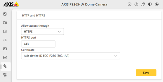
Axis devices contain a certificate to allow for encrypted HTTPS and other secure connections in order to provide the possibility to access the device securely and proceed with the initial configuration of the device. Depending on the hardware capabilities of the Axis product and which AXIS OS version it is running, different default configuration applies.
Self-Signed Certificate
Axis products with support for TPM module or Software keystore only generate a self-signed certificate during first-boot up. Axis devices come with a pre-installed self-signed certificate in order to provide the possibility to access the device via encrypted HTTPS connection and proceed with the initial setup of the device. Since the first-boot certificate is self-signed by the device, it is not suitable for providing authentication or authenticity against networks and applications. Therefore, Axis recommends removing the self-signed certificate from the device and replace it with a server certificate that is trusted in your organization when HTTPS connection is the preferred type of connection to the device.
Axis device ID (IEEE 802.1AR)
Axis devices equipped with Axis Edge Vault are provisioned with an Axis device ID. The Axis device ID conforms with the IEEE 802.1AR standard and can be verified using the Axis device ID certificate chain. ou can download and find more information about the Axis device ID certificate chain in our Public Key Infrastructure Repository. Remember to verify the downloaded certificates against the provided sha256 hash before using the Axis device ID CA certificates as a trust anchor.
Using Axis device ID in production
The IEEE 802.1AR standard for secure device identity is part of IEEE's efforts to improve security, particularly in network environments, by providing a way to uniquely identify devices. This standard enables the creation of device ID certificates, which serve as a means of authenticating network devices based on their distinct hardware characteristics. The Axis device ID complies with the IEEE 802.1AR standard.
Customers often ask whether to use the Axis device ID in production beyond the initial secure connection and onboarding. To help you make an informed decision, we’ve outlined the following benefits and drawbacks:
Benefits
Unique device identity: Provides a secure, unique identifier for each Axis device that’s tied to the device's serial number.
Device-based trust: By binding a certificate to the hardware, the network inherently trusts the device rather than solely relying on other software-based identifiers.
Hard to spoof: The Axis device identity is tied to the device's hardware keystore, which makes it highly resistant to tampering.
Out-of-box: The Axis device ID certificate is created and signed by Axis during the manufacturing process.
Zero-trust-capable: The Axis device ID certificate is pre-configured for HTTPS, IEEE 802.1X network authentication, and IEEE 802.1AE MACsec network encryption for secure device onboarding and zero-trust networking in the factory defaulted state.
Standardization: The Axis device ID is an IDevID (Initial Device Identifier), as standardized in IEEE 802.1AR, which is widely used for device authentication.
Drawbacks
Long-term validity: The Axis device ID certificate remains valid until the year 9999. The IEEE 802.1AR standard does not define how device ID certificate rotation should be handled.
Key usage: The primary purpose of the Axis device ID certificate is to authenticate the device's identity. As there are no specific key usage restrictions defined in the certificate extension, it can be utilized for both client and server certificates interchangeably.
Not changeable: The Axis device ID comes in certain cryptographies such as ECC-P256 and RSA-4096, which cannot be changed. Customers must accept these properties if they choose to use the Axis device ID in production.
Decommissioning: The Axis device ID certificate remains after factory default, while other certificates provisioned by the customer are removed.
Issuance authority: The Axis device ID is issued by Axis Communications, meaning that customers need to explicitly trust Axis Communications’ Public Key Infrastructure (PKI).
Certificate revocation: Currently, Axis doesn’t maintain a publicly accessible Certification Revocation List (CRL).
The Axis device ID certificate is extremely helpful when your primary concern is device-level authentication in a trusted network environment. One of its key benefits is facilitating secure initial device onboarding. Following successful initial authentication, we strongly advise uploading customer-specific, production-grade certificates to the device to support IEEE 802.1X, HTTPS, and other applications, thereby enhancing overall security and compliance.
CA certificates
CA certificates are certificates used by the Axis device to validate/verify the authenticity of other servers in the network. This means that CA certificates that are going to be uploaded in the CA certificate section of the Axis device need to fulfill one of the following:
X509v3 CA certificate with basicConstraints extension CA:TRUE*
X509 v1 self-signed certificate
The keyUsage attribute extension with bit keyCertSign set but without basicConstraints
Netscape Certificate Type extension saying that it is CA certificate
*The CA:TRUE or CA:FALSE attribute also decides whether the CA certificate is allowed to sign other certificates.
Installing a concatenate certificate file that contains the whole certificate chain is not currently supported. You should install the intermediate CA certificate and CA certificate separately.
Certificate signing request (CSR)
A certificate signing request (CSR) can be created from an already existing certificate in the Axis device. The certificate request in PEM format can be sent to a certificate authority (CA) for signing/verifying. After the signed certificate is returned from the CA, it needs to be uploaded on the Axis device and be compared/verified with the original certificate request. If all information is correct, the certificate upload will end successfully. However, if system changes occur between the time the CSR was issued and the certificate was uploaded, the process can be interrupted. Possible reasons why a certificate upload would fail are:
The Axis device has been factory defaulted in the meantime
The certificate used for the signing request has been removed or changed in the Axis device
Certificate browser warnings
Why do Axis products include self-signed certificates or IEEE 802.1AR identity certificates from factory?
IT-security and industry best practice is to provide secure, encrypted HTTPS communication in IoT devices from factory. Providing Axis devices with these certificates and having HTTPS enabled from the factory ensures that secure and encrypted communication can be used from the very first moment of communication, e.g. for HTTPS access.
Why do modern browsers flag self-signed certificates and IEEE 802.1AR identity certificates as “Not Secure”?
Modern browsers verify HTTPS connections using certificates signed by trusted Certificate Authorities (CAs), as well as performing additional checks, such as on the expiry date, and a verification of the Common Name in the certificate to see if it matches the actual URL address.
Unfortunately, web browsers cannot verify a self-signed certificate generated during the first boot up by the Axis device, and the same applies to the IEEE 802.1AR Secure Device Identity certificate (Axis Device ID) loaded into the Axis device during production. This is why web browsers show warnings like “Your connection is not private.”
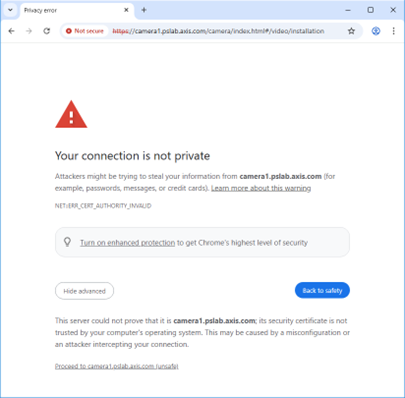
It is important to understand that the network connection is still encrypted and secure. The browser’s warning simply implies that the certificate could not be completely verified, which is why most browsers offer an additional manual step, asking the user if they wish to continue with the network connection.
Why are these certificates not trusted?
A trusted HTTPS certificate must be issued by a recognized CA. Self-signed certificates are created by the device itself, meaning the browser cannot confirm the device’s authenticity. Axis uses self-signed certificates solely for initial secure access when no PKI is available.
Most Axis products nowadays instead provide an IEEE 802.1AR-conformant secure device identity (Axis Device ID), which offers a verifiable certificate chain. The browser, however, will still show a warning, as other certificate verification steps cannot be completed successfully. For use in a production network, pre-loaded certificates should be replaced with a customer-selected, trusted CA-signed certificate.
What is the technical reason?
Even with a valid CA-signed certificate such as the Axis device ID, browsers will still reject it if the hostname/IP address used to access the device (browser URL) doesn’t match the certificate’s Common Name identity fields. Modern browsers require matching values in the Subject Alternative Name (SAN), not just the Common Name (CN). The reason behind this is that TLS certificates in the context of browser verification were designed to work specifically for users accessing websites – IoT devices were never taken into consideration and no standardized solution for how browsers could more accurately verify IoT device certificates was planned.
For example, accessing an Axis device using: https://camera01.axis.com requires the certificate to include:
SAN: camera01.axis.com (and any IP/DNS entries used)
CN: camera01.axis.com
If the certificate contains a different name (e.g. axis-device.local) or if SAN entries are missing, the browser will show a warning for “Common name invalid”. This is common for IoT devices because they often use a dynamic IP address, have multiple hostnames, or they might be accessed via an IP address that requires IP address SAN entries.
An IEEE 802.1AR-conformant secure device identity certificate that most Axis products use nowadays looks like this:
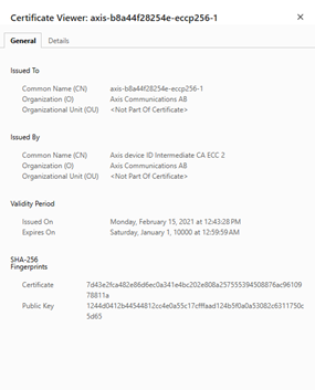
Note the Common Name “axis-b8a44f281db4-eccp256-1”. If the Axis device is configured to use that certificate for HTTPS connections and the device has the IP-address 192.168.0.101, this results in a mismatch in the used URL vs the Common Name (CN) in the certificate, which would result in the browser showing a warning message.
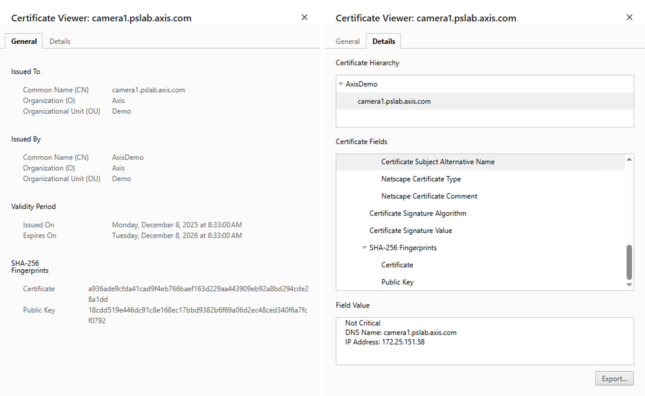
Apart from the Common Name (CN) verification, other certificate attributes are also checked and verified, which could also result in a browser warning when these are not correctly configured. To be considered valid, an IoT device certificate should have the following attributes/information correctly included in their certificate:
A trusted certificate chain that can be verified by a CA
A SAN entry matching the hostname or IP address used
The validity period (certificate start and expiry date)
Correct key usage (including Server Authentication)
Self-signed certificates typically fail the chain-of-trust check and often the hostname match, which leads to browser warnings.
AXIS IP Utility pre-installs the Axis Device ID certificate chain and allows users to access the device’s web interface without additional browser warnings.
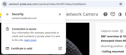
What is a good example of a customer-owned PKI?
The configuration below illustrates an Axis device using a sample customer-owned PKI certificate, along with the corresponding configuration, including a DNS-name configuration that passes all TLS/certificate verifications that a typical browser would perform. Important to note is that the IP address of the Axis device maps correctly to a configured DNS name used by the browser to access the device. Furthermore, this DNS name matches the Common Name (CN) and Subject Alternative Name (SAN) in the actual certificate presented by the Axis device.
Default HTTP(S) headers
AXIS OS by default has the following most common security-related HTTP(S) headers enabled to increase overall minimum cybersecurity in factory defaulted state. The custom HTTP header VAPIX API can be used to configure further HTTP(S) headers. For more information, see the Vapix Library.
AXIS OS 10.1 and higher
With AXIS OS 10.1 or higher, the below default HTTP(S) headers have been introduced to increase overall minimum cybersecurity level:
| Header | Values | Description |
| X-Frame-Options | SAMEORIGIN | This specifies that the page can only be embedded in a frame on the same domain as the page itself. |
| X-Content-Type-Options | nosniff | This value instructs the browser to not interpret files with an unknown MIME type as a different content type. For example, if a server sends an HTML file with a .jpg extension, the browser will not treat it as an image but instead will display it as text. |
| X-XSS-Protection | 1; mode=block | This value instructs the browser to enable its built-in XSS protection feature. |
AXIS OS 11.5 — 11.11
With AXIS OS 11.5 —11.11, a Content-Security-Policy (CSP) HTTP(S) response header is added in addition to specify a policy that tells the browser which sources of content can be trusted for the Axis device. This header can be used to protect against various types of attacks, including cross-site scripting (XSS) and data injection attacks.
When a browser receives a web page, it checks the CSP header to determine which sources of content are allowed to be loaded for that page. If any content is attempted to be loaded from a source that is not on the list, the browser will block it.
| Directive | Values | Description |
| default-src | 'self' | This specifies the default sources from which resources are allowed to be loaded if not explicitly specified. |
| frame-ancestors | 'self' | This specifies the sources from which frames or iframes can be loaded on the page. |
| connect-src | 'self' https://*.google-analytics.com https://*.analytics.google.com https://*.googletagmanager.com https://*.axis.com mediastream: blob: | This specifies the sources to which the page can make network requests. |
| script-src | 'self' 'unsafe-inline' 'unsafe-eval' https://www.googletagmanager.com https://*.google-analytics.com https://ssl.google-analytics.com https://*.axis.com | This specifies the sources from which JavaScript code can be loaded and executed on the page. |
| style-src | ’self'' ’unsafe-inline' | This specifies the sources from which styles can be loaded and applied on the page. |
| img-src | 'self' https://*.analytics.google.com https://www.googletagmanager.com https://*.axis.com data: blob: | This directive guards the loading of images (for example using the <img> HTML tag). |
| media-src | 'self' mediastream: blob: | This specifies the sources from which audio and video can be loaded on the page |
| object-src | 'none' | This specifies valid sources for the <object>, <embed>, and <applet> elements. |
In addition to the CSP, a Referrer-Policy header is added. HTTP requests may include the optional Referrer header, which indicates the origin or web page URL the request was made from. The Referrer-Policy header defines what data is made available in the Referrer header.
| Header | Values | Description | ||||||||||||||||||||||||||||||||||||||||||||||||||||||||||||||||||||||||||||||||||||||||||||||||||||||||||||||||||||||||
| Referrer-Policy | strict-origin-when-cross-origin | With this policy, only the origin is sent in the Referrer header of cross-origin requests. While offering more privacy it also prevents leaks of private data that may be accessible from other parts of the full URL such as the path and query string. | ||||||||||||||||||||||||||||||||||||||||||||||||||||||||||||||||||||||||||||||||||||||||||||||||||||||||||||||||||||||||
AXIS OS 12.0 and higher
With AXIS OS 12.0 and higher, the default Content-Security-Policy (CSP) HTTP(S) response header has been updated.
| Directive | Values | Description | ||||||||||||||||||||||||||||||||||||||||||||||||||||||||||||||||||||||||||||||||||||||||||||||||||||||||||||||||||||||||||||||||||||||||||
| default-src | 'self’ | This specifies the default sources from which resources are allowed to be loaded if not explicitly specified. | ||||||||||||||||||||||||||||||||||||||||||||||||||||||||||||||||||||||||||||||||||||||||||||||||||||||||||||||||||||||||||||||||||||||||||
| frame-ancestors | 'self’ | This specifies the sources from which frames or iframes can be loaded on the page. | ||||||||||||||||||||||||||||||||||||||||||||||||||||||||||||||||||||||||||||||||||||||||||||||||||||||||||||||||||||||||||||||||||||||||||
| connect-src | ‘self’ https://*.google-analytics.com https://*.analytics.google.com https://*.googletagmanager.com https://*.axis.com mediastream: blob: | This specifies the sources to which the page can make network requests. | ||||||||||||||||||||||||||||||||||||||||||||||||||||||||||||||||||||||||||||||||||||||||||||||||||||||||||||||||||||||||||||||||||||||||||
| script-src | ‘self’ https://www.googletagmanager.com https://*.google-analytics.com https://ssl.google-analytics.com https://*.axis.com | This specifies the sources from which JavaScript code can be loaded and executed on the page. | ||||||||||||||||||||||||||||||||||||||||||||||||||||||||||||||||||||||||||||||||||||||||||||||||||||||||||||||||||||||||||||||||||||||||||
| style-src | ’self’ ’unsafe-inline' | This specifies the sources from which styles can be loaded and applied on the page. | ||||||||||||||||||||||||||||||||||||||||||||||||||||||||||||||||||||||||||||||||||||||||||||||||||||||||||||||||||||||||||||||||||||||||||
| img-src | 'self' https://*.analytics.google.com https://www.googletagmanager.com https://*.axis.com data: blob: | This directive guards the loading of images (for example using the <img> HTML tag). | ||||||||||||||||||||||||||||||||||||||||||||||||||||||||||||||||||||||||||||||||||||||||||||||||||||||||||||||||||||||||||||||||||||||||||
| media-src | ‘self’ mediastream: blob: | This specifies the sources from which audio and video can be loaded on the page | ||||||||||||||||||||||||||||||||||||||||||||||||||||||||||||||||||||||||||||||||||||||||||||||||||||||||||||||||||||||||||||||||||||||||||
| object-src | ’none’ | This specifies valid sources for the <object>, <embed>, and <applet> elements. | ||||||||||||||||||||||||||||||||||||||||||||||||||||||||||||||||||||||||||||||||||||||||||||||||||||||||||||||||||||||||||||||||||||||||||
Decommissioning
When decommissioning an Axis device, a factory default should be performed. After the factory default, most data is erased by overwriting/sanitization. For more information, go to AXIS OS Hardening Guide.
Software Composition
Open source library support
AXIS OS-based network products use a variety of open source libraries. Therefore, it is critical that changes to these libraries are reflected in AXIS OS. Libraries are updated in the AXIS OS Active and LTS tracks in conjunction with the release. If there are no software restrictions, they are also updated in the PSS track.
If an open source library becomes end-of-life (EOL) by the upstream community, Axis aims to replace the library in a timely manner or provide support in a different way depending on its use within the AXIS OS-based network product. An example is listed below.
OpenSSL is used for cryptographic operations. The currently used OpenSSL 1.1.1 version is a long-term support (LTS) release which has reached its EOL during September 2023 as announced by the OpenSSL foundation.
From AXIS OS 11.6.89 and onwards, the newest OpenSSL 3.0 library (LTS) is supported in addition to the current OpenSSL 1.1.1, which will be deprecated but still usable.
Axis plans to remove OpenSSL 1.1.1 support in AXIS OS 12 after LTS 2024.
To support AXIS OS LTS tracks, Axis has a support contract agreement with the OpenSSL foundation for continued patching of OpenSSL 1.1.1.
ACAP related information
Starting from ACAP SDK version 4.14, we're integrating the latest openSSL Version 3 into the Native ACAP SDK.
Please read more in the release notes and explore API examples on GitHub for details.
What needs to be done:
If any Axis-owned ACAP relies on the OpenSSL 1.1.1 runtime dependency provided by the platform, it requires refactoring and rebuilding with OpenSSL 3 libraries. We recommend utilizing the latest ACAP SDK (4.14) to ensure compatibility with the correct library version.
Software Bill of Materials
A Software Bill of Materials (SBOM) is an inventory of all components included in the software. It has become an increasingly important and common part of software development lifecycle and processes. It allows IT Operations and Security staff to determine which third-party or open-source software is packaged with your software. Having an SBOM is important when it comes to securing your IT systems and protecting user data.
Why do Axis publish an SBOM?
Axis works actively with the principles of openness and building trust through transparency, the SBOM is a valued addition to these principles. It provides our customers with the information necessary to know whether or not the products we have provided may be vulnerable to cyber attacks.
For which AXIS OS versions?
Axis will provide an SBOM for all AXIS OS releases on active track starting with release 11.2.
What is included?
The Axis SBOM contains information about Axis-Proprietary components and Opensource software used to assemble AXIS OS.
What is excluded and why?
Due to current licensing/legal limitations we cannot provide information about third-party proprietary software. Our aim is to cover all the third-party components as legally possible if third-party vendors agree. Furthermore, some components like the Linux Kernel needs to be enriched further for more granular sub-components.
Where can I find the SBOM?
The SBOM is located together with the AXIS OS version it is based on. AXIS OS can be found in the product support or at the download page.
What format and why?
The Axis SBOM is produced in accordance with the CycloneDX SBOM specification. This format seems to be the most usable in other systems and strives to be a minimalist format easy to work with. Advantages of this format can be found here.
What is the difference between a SBOM and the Third party software licenses document?
The Third party software licenses document is meant to list all legal agreements and licenses with third parties related to any intellectual property that allows us to use, market and incorporate this into our products.
What about SBOM for other AXIS software?
This is a start, and we are looking into how SBOM is applicable to other software from Axis.
Where can I find more information about SBOM in general?
The National Telecommunications and Information Administration provides more educational information about SBOM.
How can I use the SBOM to analyze the software?
The Axis SBOM contains information about Axis-Proprietary and Opensource software used to assemble AXIS OS. The Axis SBOM can be used by third party vulnerability scanners to highlight known vulnerabilities in software packages. A vulnerability that applies to a certain module or feature in a software package needs to be loaded and used by the Axis device. Vulnerabilities in modules that are not loaded are not relevant but may still be flagged by the vulnerability scanner or SBOM information. For more information on how to work with the result of a security scanner see: AXIS OS Vulnerability Scanner Guide.
Media streaming
Video streaming in Axis products
The purpose of this section is to encourage and enable partners, system integrators and end users to consider their individual setup when configuring general video streaming settings in Axis devices in order to ensure optimal performance and user experience.
General considerations
Axis video capable devices deliver a video stream according to the desired requirements of the system it is used in and according to the specifications of the Axis device itself. The following information provides a foundation and understanding of how video streaming in Axis devices works and what settings to consider.
About video streaming clients
The Axis device as such recognizes several types of clients that it encodes and distributes video streams to. The clients can be categorized as internal and external, and they are served with video streams as they are requested. See examples below for each category:
Internal clients
Action rule for (S)FTP/HTTP(S) MJPEG image upload
Action rule for (S)FTP/HTTP(S) video clip upload
Action rule for recording videos to SD card and network share
Continuous recording to SD card or network share
(Analytics) ACAPs that request video stream or MJPEG images
External clients
Viewing video in web interface
Viewing video via secure remote access
Live view and recording to AXIS Companion
Live view and recording to AXIS Camera Station
Live view and recording to 3rd party video management system
Unique encoded streams
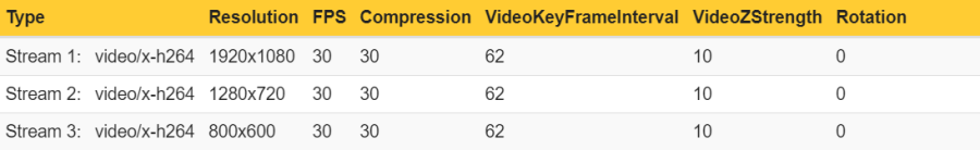
The number of unique encoded streams tells us how many different video streams an Axis device is encoding. This information can be obtained in the server report of devices with version 5.70 or higher in the section Snapshot of the current (caching) streams. For devices with AXIS OS version 10.7 or higher, this information is available in the section Snapshot of all running streams. The number of unique encoded streams are affected by stream properties, as will be shown in the examples below. Note that the illustrations are taken from a graphical user interface to better illustrate the use case.
Example 1: In this example, the Axis device is encoding a total number of three unique encoded video streams. The video streams differ in one stream property - resolution - and since the resolution is different, the Axis device needs to encode each video stream separately.
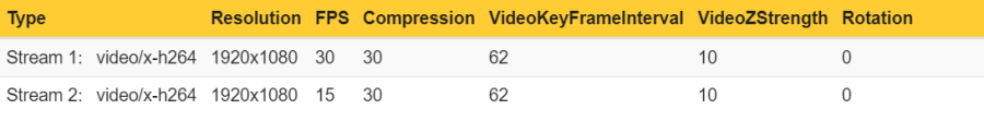
Example 2: In this example, the Axis device is encoding a total number of two unique encoded video streams. The video streams differ in one stream property - frame rate (fps) - and since the frame rate is different, the Axis device needs to encode each video stream separately.
Conclusion: Axis devices need to encode video streams according to their stream properties. If stream properties, such as fps, compression, VideoKeyFrameInterval (GOP), etc. differ from one requested video stream to another, the Axis device is forced to encode separate video streams. This may have an impact on video streaming performance and generally it is recommended to optimize the setup towards the least amount of video streams possible.
Note: From AXIS OS 10.8 and onwards a single unique encoded video stream can be distributed to a maximum of eight physical network clients at the same time. If more physical network clients need to pull the same video stream, we suggest implementing multicast video streaming instead, or to have additional clients request another unique encoded video stream.
Distributed streams
The number of distributed video streams refers to the number of actual physical network clients in the network and the number of video streams that they are requesting. For example, it would be possible to video stream from AXIS Camera Station and from the web interface of the Axis device from the same physical network client.
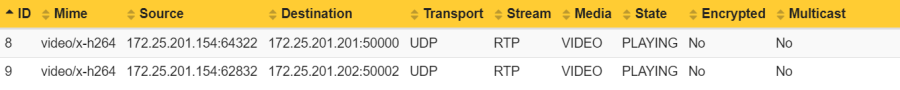
This information can be obtained in the server report of devices with version 9.80 and higher in the section Snapshots of the current outgoing RTP streams. This section lists the number of distributed streams in relation to their destination IP address. The distributed stream is declared as a ratio of Number of video streams:Number of physical network clients.
Example 1: In this example, the number of distributed streams is 2:2 because the Axis device streams in total two video streams to two physical network clients.
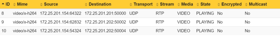
Example 2: In this example, the number of distributed streams is 3:2 because the Axis device streams in total three video streams to two physical network clients. Observe that the Physical network client 1 is requesting the Unique encoded stream 1 twice.
Conclusion: An Axis device can stream a single or many video streams to either the same or many physical network clients. A physical network client is defined by the number of video streams it is requesting and its destination IP address in the network.
Note: From AXIS OS 10.8 and onwards a single unique encoded video stream can be distributed to a maximum of eight physical network clients at the same time. If more physical network clients need to pull the same video stream, we suggest implementing multicast video streaming instead, or to have additional clients request another unique encoded video stream.
Unique encoded streams and distributed streams
With the information above, we can now explain the relation between the number of unique encoded streams in relation to the number of distributed streams to physical network clients.
Example 1: In this example, two physical network clients are requesting a unique encoded stream each. This results in a distributed stream to each physical network client.
Example 2: In this example, the Axis device is encoding two unique streams and distributes them to three physical network clients.
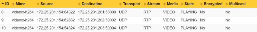
Example 3: In this example, the Axis device is encoding a single unique stream and distributes it to two physical network clients via multicast. Observe that this setup would result in a single distributed stream only as the two physical network clients will receive the stream from the multicast address. So, multicast has the advantage of consuming less network bandwidth compared to example 4 below.


Example 4: In this example, the Axis device is encoding a single unique stream and distributes it to two physical network clients via unicast instead. Compared to example 3, this setup would require the Axis device to consume more network bandwidth as the unique stream has to be distributed twice.
Maximum number of clients
Another important setting is the maximum number of clients (=viewers) that can receive a video stream. The number is set to 10 or 20 in all Axis devices and is depending on the configuration and performance capabilities of the device.
This means that either the Axis device is delivering a single video stream to 10 or 20 different physical clients in the network, or the Axis device is delivering 10 or 20 different video streams to one client in the network. The number of receiving video clients (physical and software instances) is the main limit. This configuration can be obtained by reading out the following VAPIX parameter: https://ip-address/axis-cgi/param.cgi?action=list&group=Image.MaxViewers
In practice, the maximum number should never be reached at any point. If an increasing number of clients need to access the video stream, it is recommended to make use of e.g. multicast.
Video, audio and metadata
In Maximum number of clients, we learned that there is a limit to how many video streams a device can deliver as a maximum, and we explained this with the number of video streams. In addition to video streams, Axis devices can also deliver audio and metadata streams. While the purpose of video and audio streams is self-explanatory, the purpose of metadata might not be. With a metadata stream, an application or VMS can listen to the Axis device’s event stream and both react on it and create its own events and actions in return.
Below is an example of an Axis device that is currently streaming one of each stream type to a single physical network client. Observe which stream type is streamed under Media.
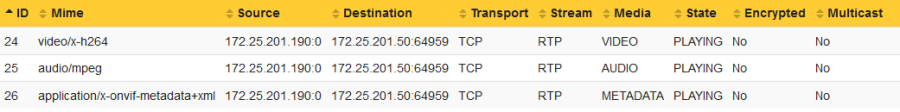
To summarize, the maximum number of clients is applied to video, audio and metadata streams separately, meaning that if the parameter MaxViewers is configured to 20, the Axis device can deliver 20 x video, 20 x audio and 20 x metadata streams in total.
Performance considerations and maximum bitrate
Performance considerations
While it’s possible for an Axis device to encode multiple video streams simultaneously, this will at some point have an impact on the performance if “too many” unique video streams are encoded. In the example illustration below, you can observe that the Axis device can deliver five unique video streams in full frame rate of 30 fps. In case a sixth unique video stream needs to be encoded, the performance of the product will be exceeded, causing the Axis device to deliver all of the requested video streams equally in reduced frame rate. In case of exceeding the performance of the product, the Axis device will not prioritize any of the video streams to be delivered in full fps, instead it will distribute the performance bottleneck across all video streams.
Note that the above example is an oversimplified illustration and the number of concurrent video streams an Axis device can deliver in full frame rate is heavily dependent on a lot of factors, such as requested frame rate, resolution, compression, bitrate and many more. It’s recommended to test the device against the desired behavior in an environment that is exact, or close to, the environment the device is installed in.
Maximum video stream bitrate
A typical H.264 video stream in 1080p and 30 fps will have a bitrate of approximately 1 Mbit/s to 10 Mbit/s depending on scene, lighting conditions, movement and many other factors. In order to avoid network bottlenecks and congestion of the underlying network infrastructure which the Axis device is connected to, the maximum bitrate of a video stream is hard-capped and cannot exceed 50 Mbit/s per video stream in total.
Video source buffer configuration
In addition to the above information, the below listed Axis devices have additional video buffer configurations that must be considered. These devices have a limited number of statically configured so called video source buffers. The number of video source buffers depends on the device.
For single-sensor products the video source buffer can deliver at least one unique video stream, and for multi-sensor products the video source buffer can deliver at least four unique video streams. So, Axis devices containing video source buffer configurations are limited by the amount of unique video streams they can provide.
Products released before 2022
In Axis devices released before 2022, there are a maximum of four video source buffers.
Main source buffer: The main source buffer is statically configured to the device’s maximum default resolution and can only deliver a unique video stream in that specific resolution. This is indicated by the "fixed" term.
2nd source buffer: The 2nd source buffer is a low resolution video buffer suitable for applications that rely on a lower sized resolution, such as (analytics) ACAP’s or motion jpeg image. This buffer provides variations of possible resolutions.
3rd source buffer: The 3rd source buffer is a high resolution video buffer providing either the device’s maximum resolution, or a resolution close to it. In addition to that, HDMI capable devices allocate the 3rd source buffer HDMI video streaming when enabled. This buffer provides variations of possible resolutions.
4th source buffer: The 4th source buffer is a high resolution buffer providing either the device’s maximum resolution or a resolution close to it. This buffer provides variations of possible resolutions.
Products released in 2022 and onwards
In Axis devices released in 2022 and onwards, there are at least four video source buffers available for encoded video such as H26X and MJPEG. HDMI will not affect the available number of source buffers for encoded video. ACAPs (typically analytics applications) that fetches YUV will not affect the available number of source buffers for encoded video.
Fixed source buffer (Main): The fixed source buffer is statically configured to the device’s maximum default resolution and can only deliver a unique video stream in that specific resolution. This is indicated by the "fixed" term.
2nd source buffer: The 2nd source buffer is a low resolution video buffer suitable for applications that rely on a lower sized resolution motion JPEG image. This buffer provides variations of possible resolutions.
Nth source buffer: The Nth source buffer is a high resolution video buffer. This buffer provides variations of possible resolutions.
Example illustration
| Axis device | Main source buffer | 2nd source buffer | 3rd source buffer | 4th source buffer |
| AXIS Q6125-LE | Fixed 1920x1080 | 320x240 to 720x576 | 320x240 to 1920x1080 | 320x240 to 1280x960 |
In summary, this device can deliver 2 x unique video streams in max 1920x1080 resolution — one in max 1280x960 and one in 720x576. As described in Unique encoded streams, the information in the server report can help identifying which of the video source buffers that are already used and saturated, and which are still available.
Example 1: In this example, the Axis device is delivering the following unique video streams which means the Main, 3rd and 4th video source buffers are in use. Requesting e.g. another unique video stream in 1920x1080 resolution with fps = 15 would fail because no video source buffer is available to deliver this request.
Example 2: In this example, the Axis device is delivering the following unique video streams which means the Main and 3rd video source buffer are in use. Requesting e.g. another unique video stream in 1920x1080 resolution with fps = 15 would fail because no video source buffer is available to deliver this request. Requesting a unique video stream buffer in 800x600 resolution can however be delivered by the 4th source buffer.
Axis device specifics
Below are all Axis devices and their video source buffer configurations listed:
| Axis device | Main source buffer | 2nd source buffer | 3rd source buffer | 4th source buffer |
| AXIS I8116-E | Fixed 2592x1944 | 320x240 to 640x480***** | 320x240 to 1920x1080***** | 320x240 to 1920x1080***** |
| AXIS M1025 AXIS M3005-V AXIS M3025-VE | Fixed 1920x1080 | 320x240 to 720x576 | 320x240 to 1920x1080 | 320x240 to 1280x720 |
| AXIS M1004-W AXIS M1014 AXIS M1034-W AXIS M3004-V AXIS M3024-LVE | Fixed 1280x800 | 320x240 to 720x576 | 320x240 to 1440x900 | 320x240 to 1280x720 |
| AXIS M1013 AXIS M1033-W AXIS M1143-L | Fixed 800x600 | 320x240 to 720x576 | 320x240 to 800x600 | 320x240 to 800x600 |
| AXIS M3046-V 2.4 mm | Fixed 2688x1520 Fixed 2560x1440 | 320x240 to 720x576 | HDMI: 1080p 320x240 to 1920x1080 | 320x240 to 1280x720 |
| AXIS M1045-LW AXIS M1065-L/-LW AXIS M3045-V/-WV | Fixed 1920x1080 | 320x240 to 720x576 | HDMI: 1080p 320x240 to 1920x1080 | 320x240 to 1280x720 |
| AXIS M3044-V/-WV | Fixed 1280x720 | 320x240 to 720x576 | No HDMI 320x240 to 1280x720 | 320x240 to 1280x720 |
| AXIS M2026-LE AXIS M2026-LE Mk II AXIS M3106-L/-LVE AXIS M3106-L/-LVE Mk II | Fixed 2688x1520 | 320x240 to 720x576 | No HDMI 320x240 to 1920x1080 | 320x240 to 1280x960 |
| AXIS M3046-V 1.8 mm | Fixed 2304x1296 (16:9) Fixed 2016x1512 (4:3) | 320x240 to 720x576 | HDMI: 1080p 320x240 to 1920x1080 | 320x240 to 1280x960 |
| AXIS M4206-V/-LV | Fixed 2048x1536 | 320x240 to 720x576 | HDMI: 1080p 320x240 to 1920x1080 | 320x240 to 1280x960 |
| AXIS M4215-V/-LV | Fixed 1920x1080 | 320x240 to 640x360***** | 320x240 to 1920x1080***** | 320x240 to 1920x1080***** |
| AXIS M4216-V/-LV | Fixed 2304x1728 (4:3) | 320x240 to 640x480***** | 320x240 to 1920x1080***** | 320x240 to 1920x1080***** |
| Fixed 2304x1296 (16:9) | 320x240 to 640x360***** | 320x240 to 1920x1080***** | 320x240 to 1920x1080***** | |
| AXIS M3016 AXIS M3066-V AXIS M3206-LVE | Fixed 2304x1728 Fixed 2304x1296 | 320x240 to 720x576 | HDMI: 1080p 320x240 to 1920x1080 | 320x240 to 1280x960 |
| AXIS M3015 AXIS M3065-V AXIS M3075-V AXIS M3205-LVE AXIS Q9216-SLVE | Fixed 1920x1080 | 320x240 to 720x576 | HDMI: 1080p 320x240 to 1920x1080 | 320x240 to 1280x960 |
| AXIS M3064-V | Fixed 1280x720 | 320x240 to 720x576 | No HDMI 320x240 to 1280x720 | 320x240 to 1280x720 |
| AXIS M3047-P* | Fixed 2048x2048 | 480x480 to 720x720 | HDMI: 720p 480x480 to 2048x2048 | 480x480 to 720x720 |
| AXIS M3048-P* | Fixed 2880x2880 | 480x480 to 720x720 | HDMI: 720p 480x480 to 2880x2880 | 480x480 to 720x720 |
| AXIS Q6125-LE | Fixed 1920x1080 | 320x240 to 720x576 | 320x240 to 1920x1080 | 320x240 to 1280x960 |
| AXIS P1428-E** AXIS Q6128-E** | Fixed 3840x2160 | 240x135 to 640x480 | 480x270 to 1280x720 | 240x135 to 1920x1080 |
| AXIS Q6010-E*** AXIS Q6100-E*** | Fixed 2592x1944 | 320x240 to 1280x960 | 320x240 to 1920x1080 | Not available |
| AXIS P3719-PLE**** | Fixed 2560x1440 | Fixed 640x360 | 640x360 to 1920x1080 | Fixed 2560x1440 |
| AXIS M2035-LE | Fixed 1920x1080 | 320x240 to 640x360***** | 320x240 to 1920x1080***** | 320x240 to 1920x1080***** |
| AXIS M2036-LE | Fixed 2304x1728 (4:3) | 320x240 to 640x480***** | 320x240 to 1600x1200***** | 320x240 to 1600x1200***** |
| Fixed 2688x1512 (16:9) | 320x240 to 640x360***** | 320x240 to 1920x1080***** | 320x240 to 1920x1080***** | |
| AXIS M3085-V | Fixed 1920x1080 | 320x240 to 640x360***** | 320x240 to 1920x1080***** | 320x240 to 1920x1080***** |
| AXIS M3086-V | Fixed 2688x1512 (16:9) | 320x240 to 640x360***** | 320x240 to 1920x1080***** | 320x240 to 1920x1080***** |
| Fixed 2304x1728 (4:3) | 320x240 to 640x360***** | 320x240 to 1920x1080***** | 320x240 to 1920x1080***** | |
| AXIS M3088–V | Fixed 3840x2160 | 320x240 to 640x360***** | 320x240 to 1920x1080***** | 320x240 to 1920x1080***** |
| AXIS M1055-L | Fixed 1920x1080 | 320x240 to 640x360***** | 320x240 to 1920x1080***** | 320x240 to 1920x1080***** |
| AXIS M1075-L | Fixed 1920x1080 | 320x240 to 640x360***** | 320x240 to 1920x1080***** | 320x240 to 1920x1080***** |
| AXIS P3905–R Mk III | Fixed 1920x1080 Fixed 1280x720 | 320x240 to 720x576 | 320x240 to 1920x1080 320x240 to 1280x720 | 320x240 to 1280x960 320x240 to 1280x720 |
| AXIS M3905–R | Fixed 1920x1080 Fixed 1280x720 | 320x240 to 720x576 | 320x240 to 1920x1080 320x240 to 1280x720 | 320x240 to 1280x960 320x240 to 1280x720 |
* The resolutions are only for fisheye overview and differ for other dewarped view modes. When pulling view area 1 & 2 with the same resolution on AXIS M3047-P and AXIS M3048-P, this will work either by using the highest resolution (1920x1440) or with lower resolutions like 640x480 and 480x360.
** Each source buffer can deliver two video streams in the corresponding resolution. Example: either 4x1080p in total with 2x1080p delivered from the main source buffer and 2x1080p delivered from the 4th source buffer, or 2x4K delivered from the main source buffer and 2x1080p delivered from the 4th source buffer.
*** The device is a multi-sensor device with 4 physical sensors, which translates to each buffer being able to deliver one video stream per physical sensor. Example: 1 x video stream in 2592x1944 resolution per sensor on AXIS Q6010-E makes it a total of 4 video streams on the main source buffer.
**** The 4th source buffer is allocated for quad-view only, so this means that the 4th source buffer cannot be utilized further even if quad-view is not used.
***** These video source buffers are capable of providing two unique video streams per buffer instead of just a single one.
Troubleshooting
You may refer to each device's release notes for all the supported resolutions. You will also notice the following line in the release notes for devices with hardware limitations: "5.40.5:L35026 Number of different configured video streams are limited by hardware".
A typical first hand indication that the Axis device cannot provide additional unique video streams as the video source buffers are already exceeded is the "503 Service Unavailable" error message in the web interface of the Axis device.
Other applications, like AXIS Companion or AXIS Camera Station, would show the user a "Camera error". The Server report and included log messages of Axis devices are an excellent tool to debug this kind of scenarios.
Below you can find a list of some common log messages that would appear in case the video source buffer is saturated and the Axis device is not being able to deliver a requested unique video stream
Troubleshooting example 1: In this example, requesting a unique video stream has failed due to there simply not being any video source buffer available to facilitate another unique 1024x768 video stream. The log messages indicate which source buffer is already occupied and which is still available to use at the time when the new unique video stream is requested.
<INFO> Jan 4 11:22:03 axis-00408cdc12b7 /usr/bin/ambad[960]: Unable to find available stream configuration for resolution 1024x768
<INFO> Jan 4 11:22:03 axis-00408cdc12b7 /usr/bin/ambad[960]: buffer[0]: fixed 1920x1080, current 1920x1080
<INFO> Jan 4 11:22:03 axis-00408cdc12b7 /usr/bin/ambad[960]: buffer[1]: max 720x576, current 0x0
<INFO> Jan 4 11:22:03 axis-00408cdc12b7 /usr/bin/ambad[960]: buffer[2]: max 1920x1080, current 1280x960
<INFO> Jan 4 11:22:03 axis-00408cdc12b7 /usr/bin/ambad[960]: buffer[3]: max 1280x720, current 0x0
<INFO> Jan 4 11:22:03 axis-00408cdc12b7 /usr/bin/ambad[960]: Failed to allocate a source buffer
Troubleshooting example 2: Like in the example above, requesting a unique video stream has failed due to there not being any video source buffer available to facilitate another unique 800x600 video stream.
<INFO> Jan 4 11:22:03 axis-0040 /usr/bin/ambad[960]: Unable to find available stream configuration for resolution 800x600
<INFO> Dec 30 21:15:36 axis408 /usr/bin/ambad[1051]: buffer[0]: fixed 800x600, current 800x600
<INFO> Dec 30 21:15:36 axis408 /usr/bin/ambad[1051]: buffer[1]: max 720x576, current 0x0
<INFO> Dec 30 21:15:36 axis408 /usr/bin/ambad[1051]: buffer[2]: max 800x600, current 800x600
<INFO> Dec 30 21:15:36 axis408 /usr/bin/ambad[1051]: buffer[3]: max 800x600, current 800x600
<INFO> Dec 30 21:15:36 axis408 /usr/bin/ambad[1051]: Failed to allocate a source buffer
Troubleshooting example 3: Axis devices with newer AXIS OS versions print their log message in a slightly different manner, as seen in this example.
[ INFO    ] /usr/bin/ambad[1035]: Failed to allocate a source buffer (1280x720, channel 1): No matching buffer available
[ INFO    ] /usr/bin/ambad[1035]: stream[1]: encoding [ 1920x1080, 25/1 fps, buffer_id 2, state active, channel 1 ]
[ INFO    ] /usr/bin/ambad[1035]: stream[2]: encoding [ 640x480, 25/1 fps, buffer_id 3, state active, channel 1 ]
[ INFO    ] /usr/bin/ambad[1035]: stream[3]: encoding [ 320x240, 25/1 fps, buffer_id 1, state active, channel 1 ]
[ WARNING ] monolith: Failed to allocate 1280x720 H264 stream on channel 1: Failed to allocate stream resources: Failed to add stream
[ ERR     ] monolith[925]: Could not set caching pipeline to playing.
Recommendations
The following general recommendations can be given to reduce complexity, configuration time and to optimize the video streaming setup of Axis devices:
Make use of stream profiles to package streams and their configuration in a simple way to optimize stream and configuration handling
Action rules that upload MJPEG images or video clips should utilize user-configured stream profiles
Use the same stream settings (=stream profile) for live view and recording if possible
Have in mind that action rules allocate a video source buffer once the action rule is activated. This means that even though the Axis device is supposed to send an image to an FTP server once a day, it will result in the video source buffer being allocated for the entire day
Have in mind that (Analytics) ACAPs such as AXIS Video Motion Detection or 3rd party ACAPs may consume a low resolution buffer for detection, such as 320x240
Have in mind that the “Adaptive Resolution/Streaming” feature enabled per default when accessing the Axis device’s web interface will request a unique video stream tailored to the actual resolution size of the physical display of the user. This might consume a video source buffer by itself
Avoid having anonymous viewers enabled. Besides the aspect of cybersecurity, having anonymous viewers enabled allows the uncontrolled access to an Axis device and may exceed the video source buffer configurations
Avoid questionable setups such as requesting two unique video streams in the same resolution, framerate but with different compression, like 30 and 35. The difference in image quality is negligible compared to the cost of consuming a video source buffer
Digital PTZ limits with Ambarella
When using digital PTZ in a camera with an Ambarella chip, there are certain limitations that are good to be aware of.
The maximum width of a video stream that DPTZ can be used with depends on which Ambarella chip is used (see the product’s datasheet for the chip specification).
Ambarella CV25 - Max width 1920
Ambarella CV75 - Max width 1920
Ambarella S5L - Max width 1920
Ambarella S6Lm - Max width 1280
Digital PTZ is related to view areas. The view area can be of any size, but if it is smaller than the full resolution of the sensor, it must be streamed with a width of 1920 pixels (1280 for S6Lm) or less. Streams with a greater width will show the full (uncropped) image. This also results in DPTZ not working with streams with higher resolutions.
A log message showing this limitation can look like this:
[ WARNING ] vdo[431]: Stream resolution 3840x2160 is too big to support DPTZ
Video latency
The time from an actual event happens until it's displayed on the client's screen is called latency. The latency includes processing of the image in the camera, transmission over the network, and decompression on the client. More information about latency can be found here. In some circumstances, it is desired to keep this latency as low as possible. To reduce the processing time on the camera, there are a few possibilities. Note that these settings will affect all video streams.
Choose a capture mode with higher frame rate. In high frame rate capture modes, the processing is usually performed faster than in low frame rate capture modes.
Enable LowLatencyMode (Settings > Plain config > Select group: ImageSource > ImageSource / I0 / Sensor > Low latency mode: on). In this mode, the amount of image processing is reduced to lower the latency. The drawback is that the images will become noisier, especially in low light conditions and around moving object. This will reduce the latency up to 30 - 200 milliseconds depending on camera model and settings. Depending on the Axis device, this feature is available on AXIS OS 9.80.1 or higher.
Multicast video streaming
Streaming video using multicast allows different video clients located in the network to access a single video stream which the Axis device distributes to a specific multicast address and port. One of the benefits of using multicast as a transport method for video streaming is that the Axis device keeps its system and resource consumption low by only sending a single or dual video stream to a specific address in the network. It is also an efficient way of using the network infrastructure since many different video clients can retrieve the video stream from the multicast address instead of each video client pulling a separate video stream from the Axis device. The way multicast is served, distributed and received in the network can actually minimize the bandwidth consumption of the network infrastructure and all its involved clients as such. Just imagine the difference this can make in a system with more than 5.000 Axis devices in operation.
Axis devices support a variety of ways to stream video in a multicast scenario. In the following sections we will go through multicast from a streaming perspective and not take into account the general mechanics of multicast and how it is routed through the network, or the basics of the different forms of multicast.
Any-source multicast (ASM)
Independently of the desired transport method – i.e. multicast or unicast – the initial RTSP protocol communication that is required to properly initialize the video client and Axis device is very similar, except that the video client in multicast-mode specifies this instead of the unicast scenario.
We will go through the details of a typical RTSP build-up step-by-step below. For more details, see the actual network traces in Multicast in detail.
Step 1: video client
The video client initiates the RTSP DESCRIBE and signals to the Axis device to prepare video streaming with the specified streaming parameters given in the RTSP URL and to share its corresponding Session Description Protocol (SDP) file, which includes information about how to decode the video stream.
DESCRIBE rtsp://172.25.201.100:554/axis-media/media.amp?videocodec=h265&audio=0&resolution=1920x1080&camera=1&compression=30&fps=30 RTSP/1.0
CSeq: 2
User-Agent: OmnicastRTSPClient/1.0
Accept: application/sdp
Authorization: Digest username="root", realm="AXIS_ACCC8ED910B9", nonce="00000450Y2804646c4d9f7d3175fa496417b9c4e7aa39a2", uri="rtsp://172.25.201.100:554/axis-media/media.amp?videocodec=h265&audio=0&resolution=1920x1080&camera=1&compression=30&fps=30", response="7a2e2dcad7618b36479ec76e252bc1c3"
Step 2: Axis device
The Axis device validates the request and shares the corresponding SDP file with the video client. Note that in any-source multicast mode, no multicast-specific network parameters are shared. In source-specific multicast mode (SSM), this is different.
RTSP/1.0 200 OK
CSeq: 2
Content-Type: application/sdp
Content-Base: rtsp://172.25.201.100:554/axis-media/media.amp/
Server: GStreamer RTSP server
Date: Thu, 11 Feb 2021 06:51:12 GMT
Content-Length: 1063

v=0
o=- 17136744296195211872 1 IN IP4 172.25.201.100
s=Session streamed with GStreamer
i=rtsp-server
t=0 0
a=tool:GStreamer
a=type:broadcast
a=range:npt=now-
a=control:rtsp://172.25.201.100:554/axis-media/media.amp?videocodec=h265&audio=0&resolution=1920x1080&camera=1&compression=30&fps=30
m=video 0 RTP/AVP 96
c=IN IP4 0.0.0.0
b=AS:50000
a=rtpmap:96 H265/90000
a=framerate:30
a=fmtp:96 sprop-vps=QAEMAf//AUAAAAMAgAAAAwAAAwCcEJAk;sprop-sps=QgEBAUAAAAMAgAAAAwAAAwCcoAPAgBEHy55CbkSg8quTgoKC8IAAAAMAgAAAAwKE;sprop-pps=RAHANzwEbJA=
a=ts-refclk:local
a=mediaclk:sender
a=recvonly
a=control:rtsp://172.25.201.100:554/axis-media/media.amp/stream=0?videocodec=h265&adui=0&resolution=1920x1080&camera=1&compression=30&fps=30
a=transform:1.000000,0.000000,0.000000;0.000000,1.000000,0.000000;0.000000,0.000000,1.000000
Step 3: video client
The video client then goes ahead and defines the appropriate transport method as multicast, the multicast IP address, streaming ports and the TTL. This is the important step in the RTSP build-up where the video client actually can specify the desired transport method. Note that in order for the Axis device to accept video client-specific multicast network parameters, the VAPIX parameter RTSP Allow Client Transport Settings in Plain Config > Network has to be enabled. If this parameter is not set, the Axis device might ignore these parameters and offer their own configuration set in Plain Config > Network > R0.
SETUP rtsp://172.25.201.100:554/axis-media/media.amp/stream=0?videocodec=h265&audio=0&resolution=1920x1080&camera=1&compression=30&fps=30 RTSP/1.0
CSeq: 3
User-Agent: OmnicastRTSPClient/1.0
Transport: RTP/AVP;multicast;destination=224.16.17.51;port=47806-47807;ttl=64
Authorization: Digest username="root", realm="AXIS_ACCC8ED910B9", nonce="00000450Y2804646c4d9f7d3175fa496417b9c4e7aa39a2", uri="rtsp://172.25.201.100:554/axis-media/media.amp/stream=0?videocodec=h265&audio=0&resolution=1920x1080&camera=1&compression=30&fps=30", response="48cf0f723aca20f6530e79ecb966ec0a"
Step 4: Axis device
The Axis device in return validates the request and if successful, it answers with the exact same network parameters back to the video client to prepare the upcoming session.
RTSP/1.0 200 OK
CSeq: 3
Transport: RTP/AVP;multicast;destination=224.16.17.51;ttl=64;port=47806-47807;mode="PLAY"
Server: GStreamer RTSP server
Session: f2imQtCHhuoH2FbW;timeout=60
Date: Thu, 11 Feb 2021 06:51:12 GMT
Step 5: video client
The video client then finally signals to the Axis device via RTSP PLAY to start video streaming as agreed based on the network and video streaming parameters that have been handshaked previously.
PLAY rtsp://172.25.201.100:554/axis-media/media.amp?videocodec=h265&audio=0&resolution=1920x1080&camera=1&compression=30&fps=30 RTSP/1.0
CSeq: 4
Session: f2imQtCHhuoH2FbW
User-Agent: OmnicastRTSPClient/1.0
Range: npt=0.000-
Authorization: Digest username="root", realm="AXIS_ACCC8ED910B9", nonce="00000450Y2804646c4d9f7d3175fa496417b9c4e7aa39a2", uri="rtsp://172.25.201.100:554/axis-media/media.amp?videocodec=h265&audio=0&resolution=1920x1080&camera=1&compression=30&fps=30", response="d015b378a8a1000c964d6c48d1883d1f"
Step 6: Axis device
The Axis device acknowledges the request by sending an RTSP OK and provides the video client with information about how the video stream will be momentarily available at the defined multicast network parameters. In order to signal the start of the video stream to the video client, the Axis device specifies the sequence number of the first RTP package and the initial RTP timestamp so that the client expects and processes the correct start of the video stream.
RTSP/1.0 200 OK
CSeq: 4
RTP-Info: url=rtsp://172.25.201.100:554/axis-media/media.amp/stream=0?videocodec=h265&audio=0&resolution=1920x1080&camera=1&compression=30&fps=30;seq=24067;rtptime=417717697
Range: npt=now-
Server: GStreamer RTSP server
Session: f2imQtCHhuoH2FbW;timeout=60
Date: Thu, 11 Feb 2021 06:51:12 GMT
Optional client transport setting handling Step 3: video client Step 4: Axis device |
Source-specific multicast (SSM)
While in any-source multicast (ASM) the multicast network parameters are handshaked after sharing the Session Description Protocol (SDP) file during the initial RTSP build-up, this is not the case in the source-specific multicast mode. In SSM, the multicast network parameters are pre-configured in the Axis device and shared with the requesting video client when the SDP file is shared. The benefit of this is that the requesting video client can join a multicast group and only filter for the multicast traffic the video client is interested in. This can be done by applying a source-specific filter when joining the multicast group.
A typical scenario where SSM would be beneficial is when multiple Axis devices would stream video to the same multicast address but would use different ports. A video client connecting via any-source multicast would receive the multicast traffic from all streaming devices, while a video client requesting source-specific multicast would be able to filter out unwanted traffic. On top of that, SSM allows for reliable planning of multicast routing/path-forwarding since it is known how multicast is switched and routed through the network.
Source-specific multicast requires pre-configuration on the Axis device to configure the desired multicast network parameters. You can find information on how to configure an Axis device for source-specific multicast in the VAPIX Library but is also illustrated below. There is no specific setting to enable or disable source-specific multicast as such, but the source-specific multicast network parameters that need to be defined in advance can be configured from Plain Config > Network for each individual video source. Below is a typical example configuration:
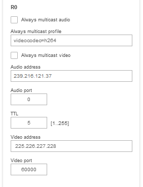
Step 1: video client
Compared to the any-source multicast mode, SSM mode requires a different streaming URL for signaling to the Axis device that source-specific multicast is wanted.
DESCRIBE rtsp://172.25.201.100:554/axis-media/ssm/media.amp?camera=1 RTSP/1.0
CSeq: 4
Authorization: Digest username="root", realm="AXIS_ACCC8ED910B9", nonce="000006c7Y356087c783187c3a95be0ca315f5fa0cd57ddc", uri="rtsp://172.25.201.100:554/axis-media/ssm/media.amp?camera=1", response="3226806a8c988f0d473df291e8c7ffb8"
User-Agent: LibVLC/3.0.11 (LIVE555 Streaming Media v2016.11.28)
Accept: application/sdp
Step 2: Axis device
The SDP file that is shared between the Axis device and the requesting video client includes the source-specific multicast network parameters which the video client has to learn in order to join the multicast group accordingly and filter for the correct traffic.
RTSP/1.0 200 OK
CSeq: 4
Content-Type: application/sdp
Content-Base: rtsp://172.25.201.100:554/axis-media/ssm/media.amp/
Server: GStreamer RTSP server
Date: Thu, 11 Feb 2021 07:01:42 GMT
Content-Length: 749

v=0
o=- 9871677480407248934 1 IN IP4 172.25.201.100
s=Session streamed with GStreamer
i=rtsp-server
c=IN IP4 225.226.227.228/5
t=0 0
a=tool:GStreamer
a=type:broadcast
a=range:npt=now-
a=control:rtsp://172.25.201.100:554/axis-media/ssm/media.amp?camera=1
a=source-filter: incl IN IP4 225.226.227.228 172.25.201.100
m=video 60000 RTP/AVP 96
b=AS:50000
a=rtpmap:96 H264/90000
a=fmtp:96 packetization-mode=1;profile-level-id=640029;sprop-parameter-sets=Z2QAKa0AxSAeAIn5ZuAgIDSDxIio,aO48sA==
a=ts-refclk:local
a=mediaclk:sender
a=recvonly
a=control:rtsp://172.25.201.100:554/axis-media/ssm/media.amp/stream=0?camera=1
a=framerate:30.000000
a=transform:1.000000,0.000000,0.000000;0.000000,1.000000,0.000000;0.000000,0.000000,1.000000
Step 3: video client
Since the video client knows the multicast network parameters that will be used in advance, the client can include them in the RTSP SETUP request.
SETUP rtsp://172.25.201.100:554/axis-media/ssm/media.amp/stream=0?camera=1 RTSP/1.0
CSeq: 5
Authorization: Digest username="root", realm="AXIS_ACCC8ED910B9", nonce="000006c7Y356087c783187c3a95be0ca315f5fa0cd57ddc", uri="rtsp://172.25.201.100:554/axis-media/ssm/media.amp/", response="89e1cf3338144d096723df0b10864cab"
User-Agent: LibVLC/3.0.11 (LIVE555 Streaming Media v2016.11.28)
Transport: RTP/AVP;multicast;port=60000-60001
Step 4: Axis device
The Axis device validates and responds with the correct multicast network parameter according to the pre-configuration done in R0.
RTSP/1.0 200 OK
CSeq: 5
Transport: RTP/AVP;multicast;destination=225.226.227.228;ttl=5;port=60000-60001;mode="PLAY"
Server: GStreamer RTSP server
Session: 06yirClN7xQCtW8q;timeout=60
Date: Thu, 11 Feb 2021 07:01:42 GMT
Step 5: video client
The requesting video client then signals to the Axis device to start video streaming to the agreed streaming and network parameters.
PLAY rtsp://172.25.201.100:554/axis-media/ssm/media.amp?camera=1 RTSP/1.0
CSeq: 6
Authorization: Digest username="root", realm="AXIS_ACCC8ED910B9", nonce="000006c7Y356087c783187c3a95be0ca315f5fa0cd57ddc", uri="rtsp://172.25.201.100:554/axis-media/ssm/media.amp/", response="c19526013f73f3db72cd4fca98ec1c40"
User-Agent: LibVLC/3.0.11 (LIVE555 Streaming Media v2016.11.28)
Session: 06yirClN7xQCtW8q
Range: npt=0.000-
Step 6: Axis device
The Axis device acknowledges the request by sending an RTSP OK and provides the video client with info on how the video stream will be momentarily available at the defined multicast network parameters. In order to signal the start of the video stream to the video client, the Axis device specifies the sequence number of the first RTP package and the initial rtp timestamp so that the client expects and processes the correct start of the video stream.
RTSP/1.0 200 OK
CSeq: 6
RTP-Info: url=rtsp://172.25.201.100:554/axis-media/ssm/media.amp/stream=0?camera=1;seq=21707;rtptime=3563678630
Range: npt=now-
Server: GStreamer RTSP server
Session: 06yirClN7xQCtW8q;timeout=60
Date: Thu, 11 Feb 2021 07:01:42 GMT
Always multicast
Always multicast is not a network multicast mode but a specific adaption to video clients that are not capable of performing a proper RTSP and/or multicast setup in either of the ways described previously (i.e. via ASM or SSM). In always multicast mode, the Axis device is statically configured to stream video to a specific multicast address and port, and also to start streaming to it directly, regardless if there are video clients in the network that are actually requesting video from that particular Axis device or not. On top of that, RTSP is not used to connect, instead the requesting video client will make a HTTP call to retrieve the Session Description Protocol (SDP) file in order to understand and make the connection to the multicast address and port where the video stream is connected. Always multicast can be configured in Axis devices in Plain Config > Network for each individual video source.
Example 1: The device will only stream video to the multicast address 224.225.226.227 and video port 50000. If video port 0 would be entered here, the Axis device would select the next possible port which has been defined in the RTP > End Port and Start Port configuration.
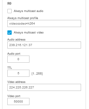
Example 2: The device will stream video to the multicast address 224.225.226.227 to port 50000, and audio to multicast address 239.216.121.37 to port 51000. Observe that it is also possible to adjust the video streaming parameters in the always multicast profile. If other streaming parameters should be used, e.g. a framerate of 15 frames per second and compression of 15, then the field can be adjusted in the following way: videocodec=h264&fps=15&compression=15. Otherwise the current configured default stream settings will be used.
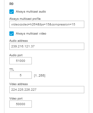
Once the above settings are saved, the Axis device will start streaming to the configured multicast address and port immediately regardless if there are clients requesting the video stream or not. The client can access this multicast stream via the SDP file, which determines the video stream settings so that the video client learns how to play the video. The SDP file can be accessed using http://ip-address/axis-cgi/alwaysmulti.sdp?camera=1 where camera=1 is mapped to R0. An example of such an SDP file can be found via alwaysmulti.sdp. Below is a network trace example illustrating the procedure.
Step 1: video client
The video client has requested the SDP file from the Axis device. Observe that no streaming parameters or multicast network parameters are mentioned by the client, hence this configuration must be performed on the Axis device prior to making the request as described in the previous examples.
GET /axis-cgi/alwaysmulti.sdp?camera=1 HTTP/1.1
Host: 172.25.201.100
Accept: */*
Accept-Language: en_US
Authorization: Basic cm9vdDpwYXNz
User-Agent: VLC/3.0.11 LibVLC/3.0.11
Range: bytes=0-
Step 2: Axis device
The Axis device looks up the current configuration in R0 and then initializes and sends the SDP file to the requesting video client. This is done in order to pass on the required information so that the video client can access the already ongoing multicast stream at the pre-configured multicast address and port. No further unicast communication is exchanged at this point, the video client will switch over to the specified multicast network parameters in order to access the stream.
HTTP/1.1 200 OK
Date: Thu, 11 Feb 2021 06:14:25 GMT
Server: Apache/2.4.46 (Unix) OpenSSL/1.1.1g
Cache-Control: no-cache, no-store, max-age=0
Pragma: no-cache
Expires: Thu, 01 Dec 1994 16:00:00 GMT
X-Content-Type-Options: nosniff
X-Frame-Options: SAMEORIGIN
X-XSS-Protection: 1; mode=block
Transfer-Encoding: chunked
Content-Type: application/sdp

v=0
o=- 1188340656180883 1 IN IP4 172.25.201.100
s=Session streamed with GStreamer
i=rtsp-server
t=0 0
a=tool:GStreamer
a=type:broadcast
a=control:*
a=range:npt=now-
m=video 50000 RTP/AVP 96
c=IN IP4 224.225.226.227/5
b=AS:50000
a=rtpmap:96 H264/90000
a=fmtp:96 packetization-mode=1;profile-level-id=640029;sprop-parameter-sets=Z2QAKa0AxSAeAIn5ZuAgIDSDxIio,aO48sA==
a=control:stream=0
a=ts-refclk:local
a=mediaclk:sender
a=framerate:30.000000
a=transform:1.000000,0.000000,0.000000;0.000000,1.000000,0.000000;0.000000,0.000000,1.000000
Multicast in detail
| Example network trace | Multicast address | Multicast port | Video client | Video client IP address | Axis device IP address |
| FFMPEG_Any_Source_Multicast.pcapng | 224.225.226.227 | 50000 | FFMPEG | 172.25.201.50 | 172.25.201.100 |
| VLC_Any-Source_Multicast.pcapng | 224.225.226.227 | 50000 | VLC* | 172.25.201.50 | 172.25.201.100 |
| Genetec_Any_Source_Multicast.pcapng | 224.16.17.51 | 47806 | Genetec | 172.25.201.51 | 172.25.201.100 |
| Milestone_Any_Source_Multicast.pcapng | 224.16.17.51 | 47806 | Milestone | 172.25.201.52 | 172.25.201.100 |
| VLC_Source_Specific_Multicast.pcapng | 225.226.227.228 | 60000 | VLC | 172.25.201.50 | 172.25.201.100 |
| FFMPEG_Always_Multicast_Direct_SDP_File_Play.pcapng | 224.225.226.227 | 50000 | FFMPEG** | 172.25.201.50 | 172.25.201.100 |
| VLC_Always_Multicast_Direct_SDP_File_Play.pcapng | 224.225.226.227 | 50000 | VLC** | 172.25.201.50 | 172.25.201.100 |
| VLC_Always_Multicast_HTTP_SDP_Play.pcapng | 224.225.226.227 | 50000 | VLC*** | 172.25.201.50 | 172.25.201.100 |
*In VLC, you may need to enable "Force multicast RTP via RTSP" in the RTP/RTSP/SDP demuxer settings under Advanced Preferences.
**In order for FFMPEG and VLC to access and retrieve the SDP file via HTTP-authentication, the HTTP-basic authentication has to be configured in Plain Config > Network > Authentication policy.
***These examples illustrate how a video client is capable of connecting to the multicast stream just by using the file SDP alone without making any further connection to the Axis device. Assuming that no configuration change is made on the Axis device, the user is only required to download the SDP file once and then one could use the SDP to start playing the video. VLC and FFMPEG are exmaples of clients that are capable of doing so.
Multicast network overview
A typical multicast scenario consists of three parts: the source, the multicast network infrastructure, and the receivers.
The Axis device is the source which sends out the streams to the multicast address. The multicast address is agreed between the clients and the device during the negotiation. The network infrastructure must be configured by network professionals. A multicast routing protocol (like PIM) needs to be running between the routers, and the IGMP protocol needs to be running between the last-hop router and the receiving clients. Additionally, IGMP snooping needs to be enabled on the layer 2 switches to avoid multicast traffic being flooded.
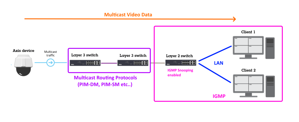
Multicast in a switched network
A network where traffic is served within a certain VLAN and IP address network is called a switched network since no layer-3 IP routing is needed. Let's start with the basic setup and assume that the network switches have not been configured properly for handling multicast traffic. What you would see is similar to the illustration below, a switched network consisting of a handful of switches with client computers and Axis devices. From all of the clients, only Client 2 is interested and requests a multicast video stream from the Axis device. Since the network switches are not configured properly at this point, the multicast traffic, which is only supposed to flow from the Axis device over the traversing switches to Client 2, will be flooded to all switches and clients in the network, regardless if they are interested in receiving the traffic or not.
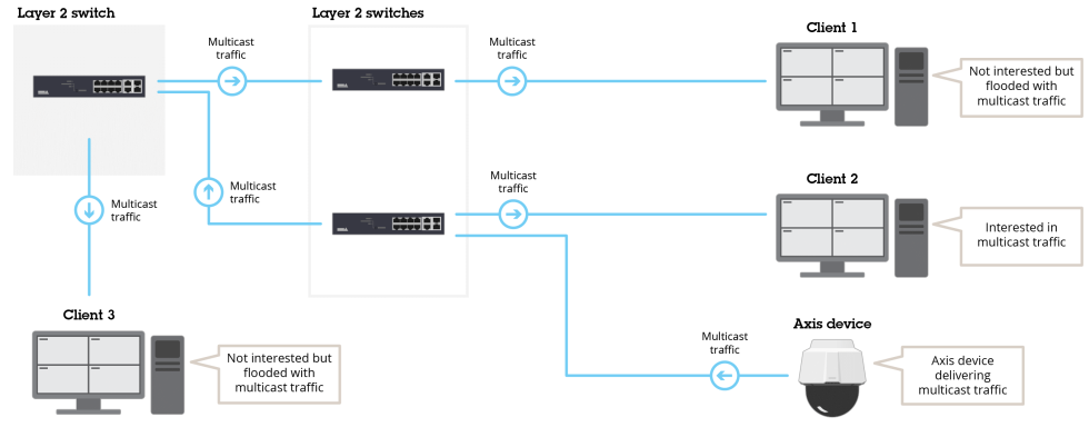
Let's look at the same network when properly configured with IGMP (Internet Group Management Protocol) enabled. IGMP is a protocol that helps the network infrastructure learn and understand who is delivering multicast traffic to which destination in order to avoid multicast flooding to non-interested clients. To configure the network to avoid multicast flooding, it is enough to configure the main switch - i.e. Layer 2 switch - for IGMP in the following example configuration:
Global configuration
ip igmp snooping querier address 172.25.201.10
ip igmp snooping querier query-interval 15
ip igmp snooping querier
By doing this, the Layer 2 switch will be sending out IGMP queries to the connected network devices in order to find out which ones are interested in receiving and sending multicast packages.
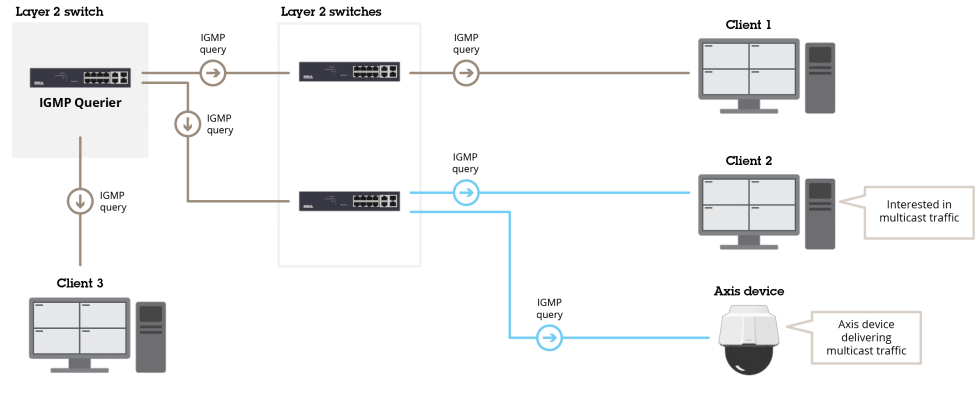
The network devices will respond with "join" messages in order to signal their participation in multicast-related traffic.
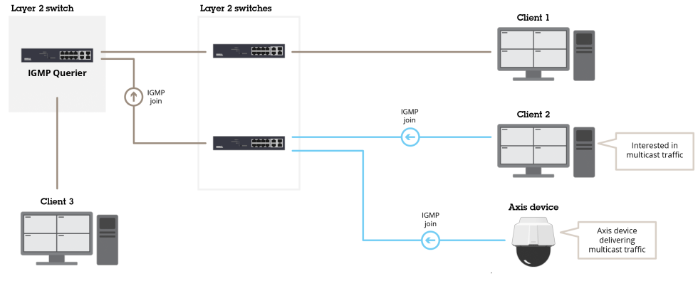
The network switches will listen and learn from this traffic in order to properly switch network packages to their appropriate destinations. In the illustration below, only Client 2 is requesting video from the Axis device via multicast.
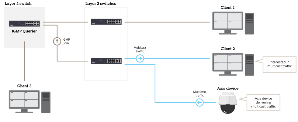
With the correct configuration in place, the network switches are now capable of switching packages as well across switches. In the illustration below, we have switched the clients, so that Client 1 requests a multicast video stream from the same Axis device that previously served Client 2. The result will be proper switched network traffic across the network to the correct destination.
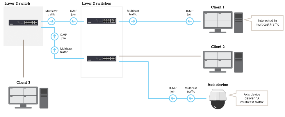
Multicast in a routed network
Multicast in a routed network does not differ essentially from a switched scenario in regards to how multicast traffic is handled. A network where clients exchange network traffic across different VLANs and IP networks is called a routed network since layer-3 IP routing techniques are needed to deliver the network traffic across. Let's re-use the same network topology as we did in the switched network scenario. The only - but important - difference is that Client 1 is placed in a different VLAN and IP address network compared to Client 2 and 3 as well as the Axis device. We assume that we have already performed the same IGMP configuration as mentioned earlier. For reference, see below:
Global configuration
ip igmp snooping querier address 172.25.201.10
ip igmp snooping querier query-interval 15
ip igmp snooping querier
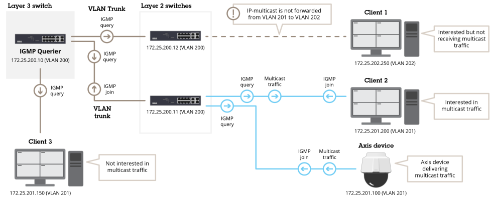
As you can see, Client 2 is already requesting video from the Axis device using multicast and since we have applied the correct IGMP configuration to the Layer 3 switch, this setup works flawlessly. But Client 1 from the other IP network also wants to receive a video via multicast, which is not working since multicast is not routed across different IP networks by design. So in order to allow multicast traffic to be routed across layer-3 networks we have to enable IP-multicast routing and use a protocol such as Protocol Independent Multicast (PIM). The most basic and simple use case would be to make use of the passive mode of PIM, as illustrated below in the suggested configuration:
Global configuration
ip multicast-routing
Configuration VLAN 201
interface Vlan201
description LAN1 clients
ip address 172.25.201.10 255.255.255.0
ip pim passive
!
Configuration VLAN 202
interface Vlan202
description LAN2 clients
ip address 172.25.202.10 255.255.255.0
ip pim passive
!
With this configuration applied, multicast is properly routed across different networks. From the Axis device located in VLAN 201 to Client 1 that is located in VLAN 202.
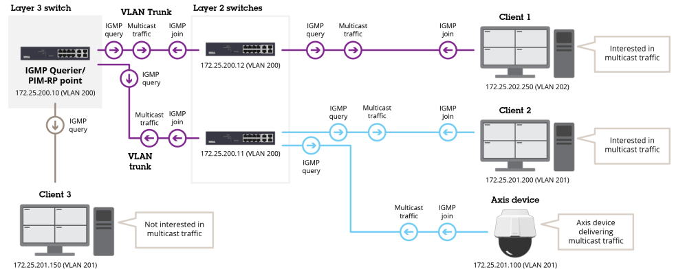
Video streaming rotation
In this section we will take a closer look at the VAPIX and ONVIF image rotation configuration when it comes to video streaming, which is handled differently depending on AXIS OS version.
AXIS OS 8.50 and higher
After support for ONVIF Profile T was added, the handling of image rotation in Axis devices has been completely separated between VAPIX and ONVIF. This means that both protocols have dedicated parameters for image rotation configuration, and that the image rotation parameter for one protocol does not affect the other and vice-versa. For VAPIX this is configured via the image rotation parameter Image.I0.Appearance.Rotation, either in the image settings in the web interface, or directly via VAPIX HTTP request. For ONVIF it's configured in the ONVIF media stream profiles in the web interface, or directly via the script editor for legacy devices in the configuration file: /etc/ws/onvif/media/media.conf.
Exception: The above is not true for Axis devices with support for ImageSource.I0.SourceRotation=yes. On these devices, the image rotation parameter is set globally via VAPIX and ONVIF will adapt to it accordingly.
AXIS OS 8.40 and lower
Configuring the image rotation parameter Image.I0.Appearance.Rotation via the image settings in the web interface or directly via VAPIX HTTP request will affect both VAPIX and ONVIF video streams. ONVIF video streams will adapt to the same image rotation configured via VAPIX, unless specified otherwise in the ONVIF stream profile settings.
Example configurations
VAPIX configuration of image rotation from the device web interface:
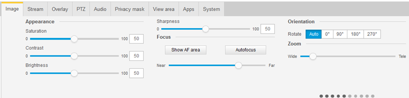
ONVIF configuration of image rotation from the device web interface:
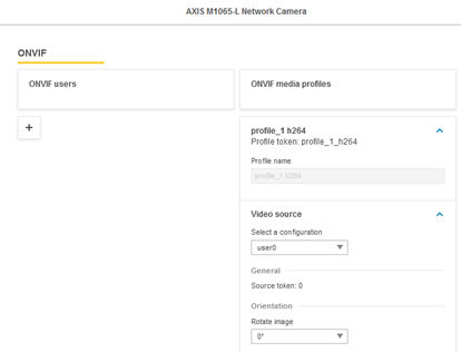
ONVIF configuration of the image rotation via script editor:
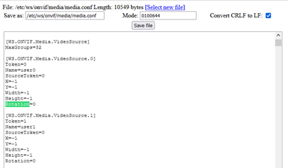
Streaming timestamps
In this section you can read about different ways to receive timestamp information when streaming video and downloading single images from Axis devices. This metadata information can be used for processing in business applications, e.g. when receiving metadata about how many persons in a store went through a certain area. It can also be used in other use cases where time-synchronisation towards 3rd party video clients is needed
H.264/MJPEG and RTP timestamps
The following network trace can be used for testing what is described below.
RTP timestamps can be found in the payload of RTP packages and function as a monotonic timestamp that can be used to identify a specific frame of the video stream. Based on the clock rate that is computed during the video stream build-up, the RTP timestamp is expected to increase incrementally from one frame to another.
The clock rate depends on the image frequency of the video stream. In this example, the video stream consists of 30 frames per second, which means the computed clock rate will be 3000. This in turn means that the monotonic RTP timestamp will increase by 3000 upon every new I-Frame or P-Frame as you can see in the following two screenshots.
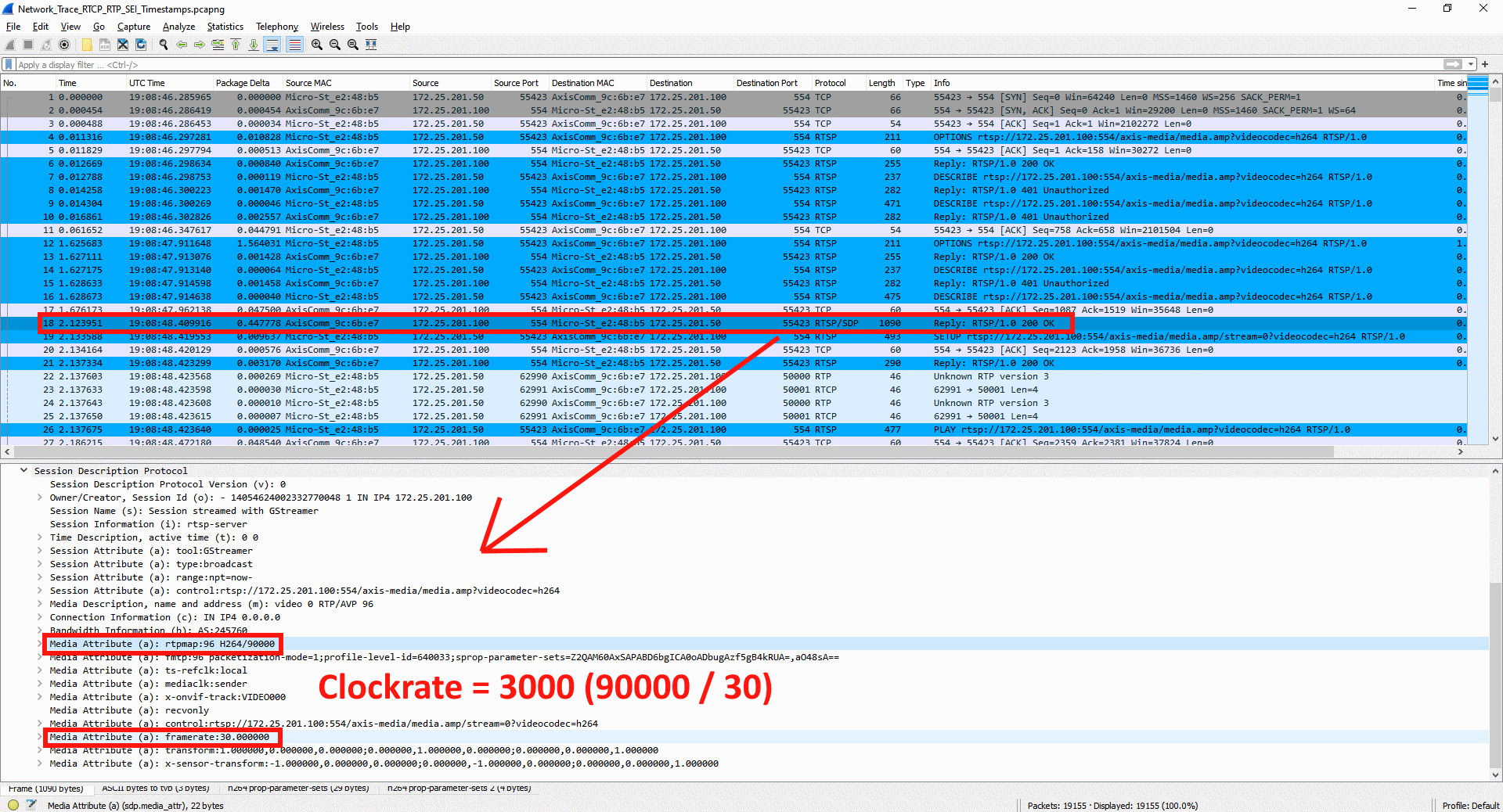
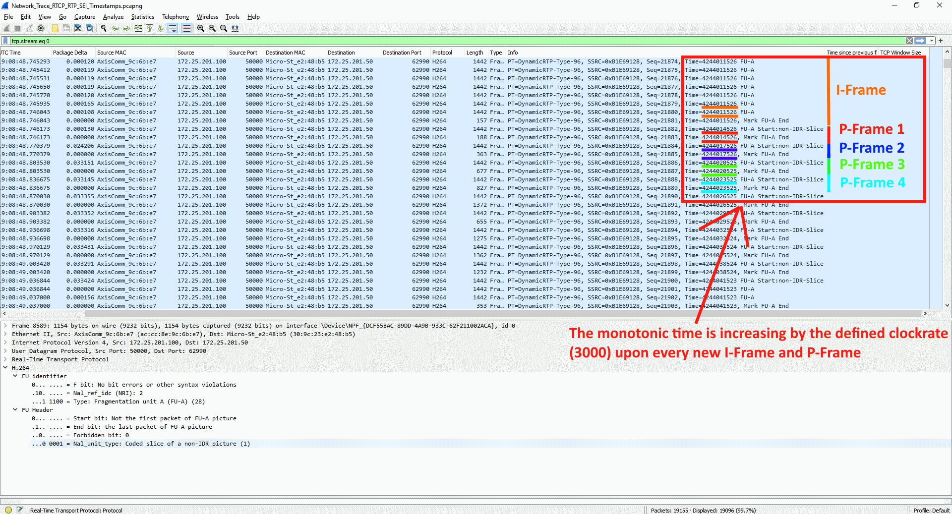
When the video stream starts, the Axis device will let the external video client know about the initial RTP timestamp of the first frame (I-Frame), as you can see below. This allows the receiving video client to identify e.g. missing frames and can be used for RTP timestamp drift measurement while the video stream is ongoing.
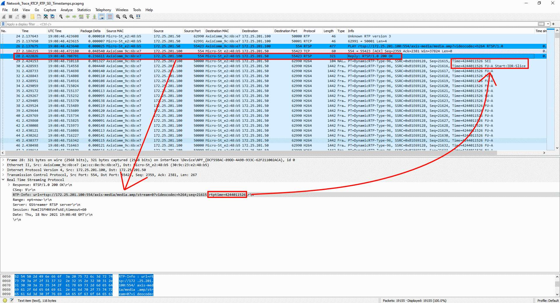
An I-Frame and/or P-Frame can consist of several RTP packages. As you can see, all packages that belong to the same I-Frame have the same unique timestamp, while each of the following P-Frames have their own timestamp corresponding to the clock rate. So for each unique I-Frame or P-Frame, the RTP timestamp increases incrementally.
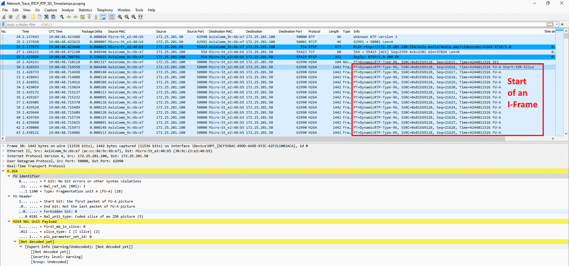
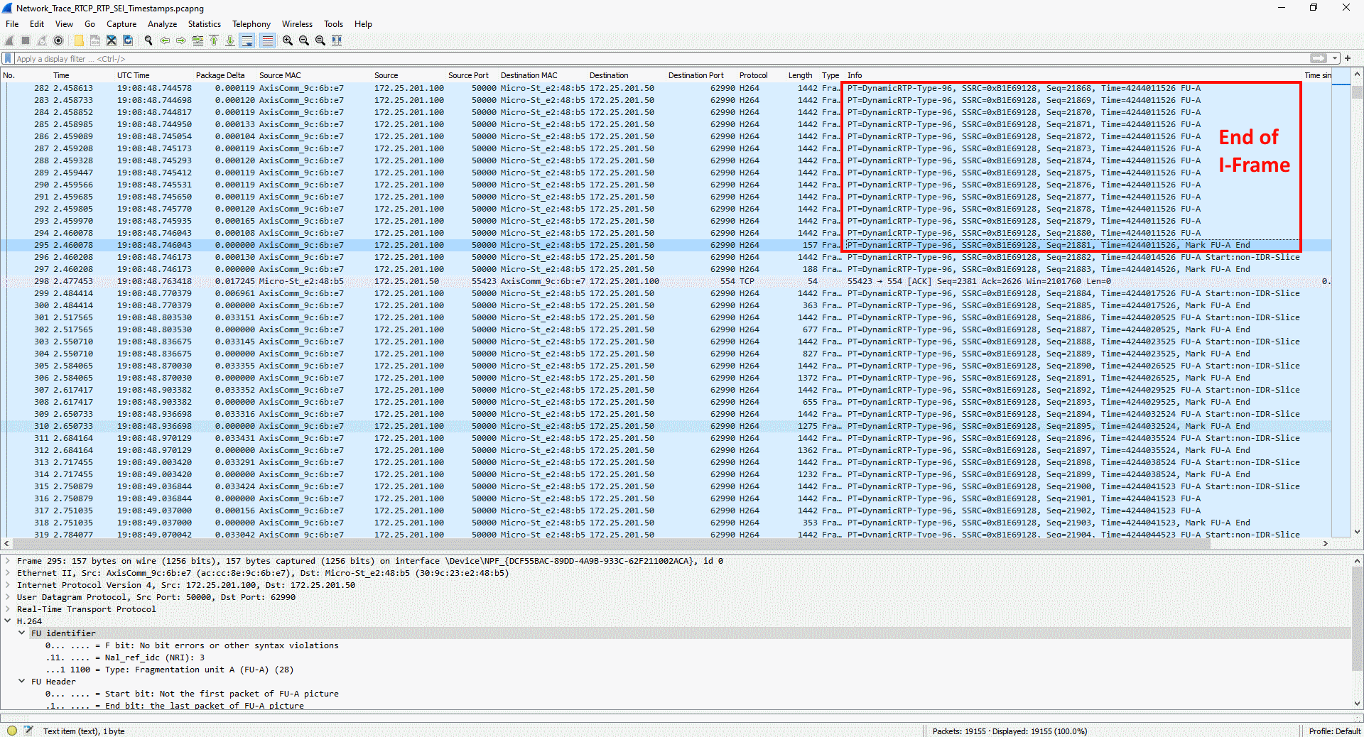
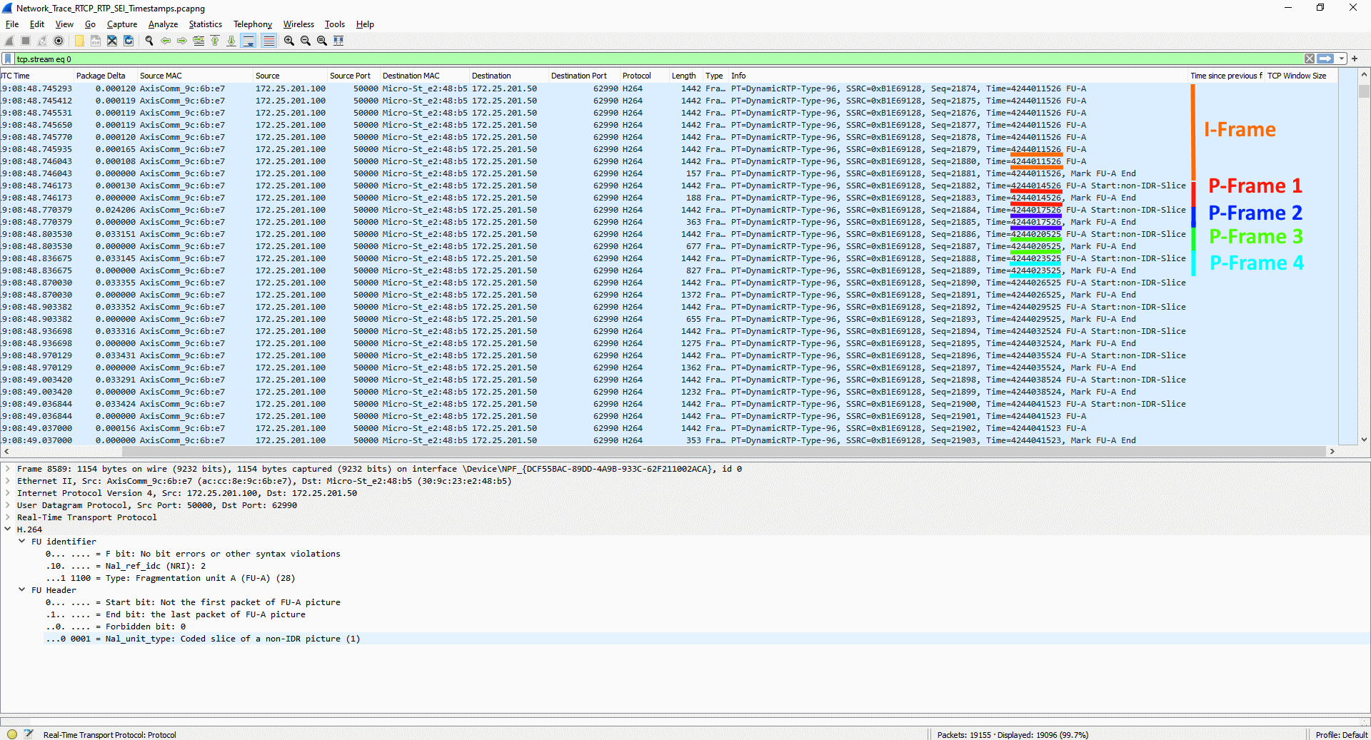
RTCP NTP timestamps
The following network trace can be used for testing what is described below.
If RTCP communication takes place between an Axis device and a video client, so called RTCP sender and receiver reports are exchanged. These reports include important information about the clock-sync within an ongoing RTSP/RTP stream. The Axis device, being the sender of the video, sends the RTCP sender report where the current RTP stream time and the current NTP timestamp in UTC are included.
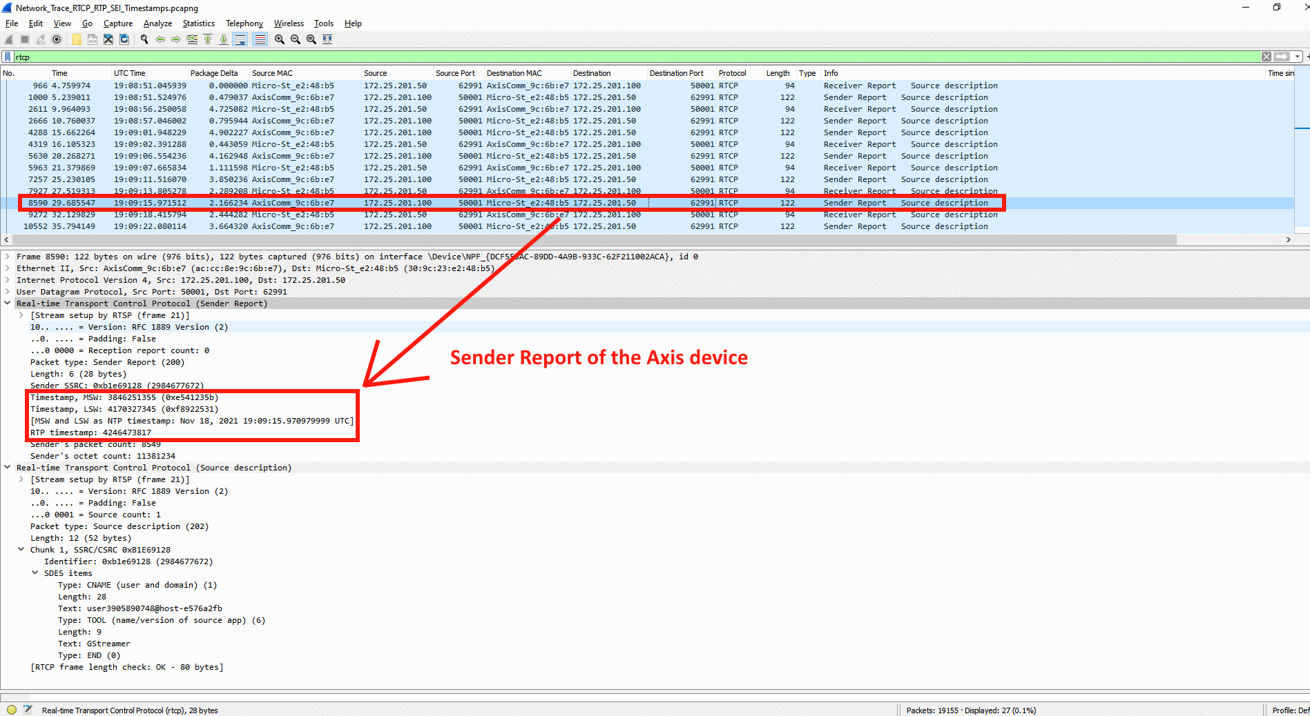
The receiving video client on the other hand exchanges the so called RTCP receiver report with the Axis device to reply to the information previously sent, and to allow for mutual time-synchronisation checks and compensation for time drift between the Axis device and the video client itself. RTCP sender and receiver reports are exchanged every couple of seconds of an ongoing video stream.
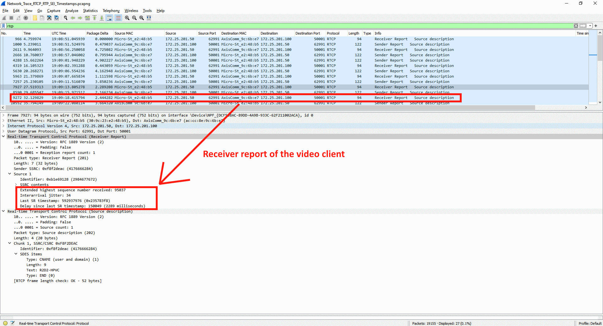
SEI timestamps
The following network trace can be used for testing what is described below.
The so called SEI frame is available when this VAPIX parameter is enabled: Image.I0.MPEG.UserDataEnabled=yes. Here Image.I0 corresponds to the default video source, and if multiple video sources are available, the parameter needs to be enabled for each video source.
SEI frames are sent from the Axis device right before every I-Frame and include useful timestamp information. As described in the VAPIX library, SEI frames include timestamp information in Linux Epoch time down to 1/100ms accuracy in HEX format.
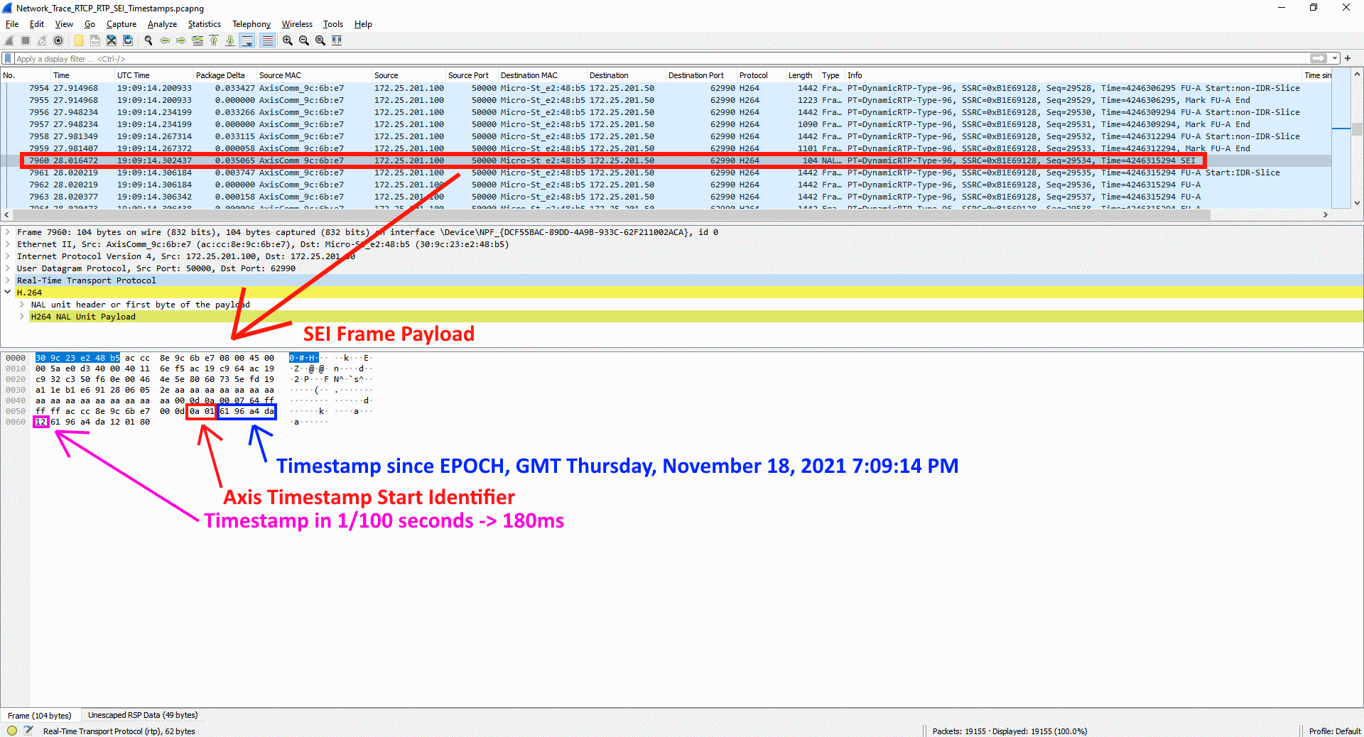
For debugging purposes we recommend using the following online converters:
Image timestamps
A single image can be downloaded from the Axis device using the following VAPIX request: http://ip-address/axis-cgi/jpg/image.cgi. The received JPEG image from the Axis device provides valuable timestamp information from either the JPEG header itself or from the EXIF header data, depending on the AXIS OS version of the Axis device.
AXIS OS 8.40 and higher
From AXIS OS 8.40, the EXIF header data can be used to obtain timestamp information as you can see in the screenshot below. For debugging purposes, a simple windows application such as JPEGSnoop or EXIF in Linux OS can be used to obtain the information provided from the EXIF header. Go to the following source for more information about JPEG and EXIF timestamp header information: Exif 2 specification.
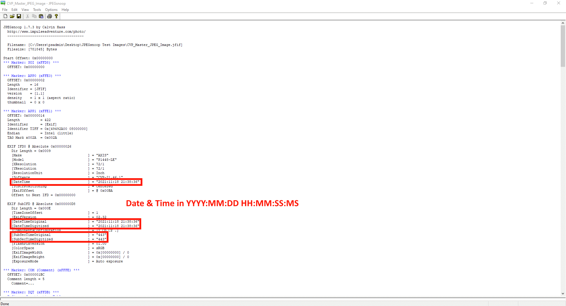
AXIS OS 6.50 and lower
Since the EXIF header data is not available in older AXIS OS versions, the plain JPEG comment header can be used to receive timestamp information. An application such as the HxD editor can be used to obtain the timestamp information in HEX-format, which in turn can be converted to human readable time format using a Linux EPOCH time converter, e.g. https://www.epochconverter.com/hex. For the 1/100 seconds information, a simple Hex to decimal converter can be used, e.g. https://www.rapidtables.com/convert/number/hex-to-decimal.html.
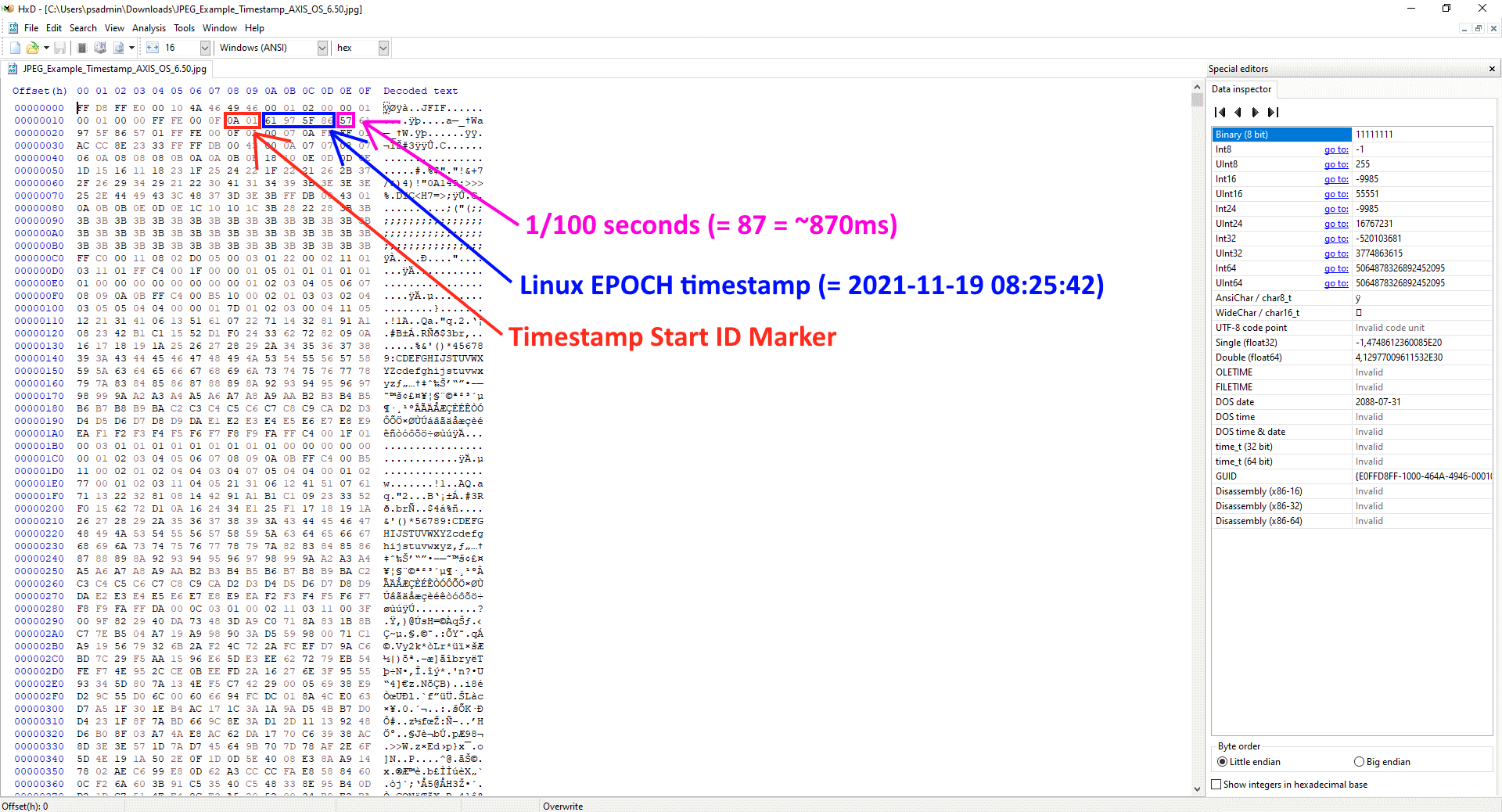
These sample images can be used for testing:
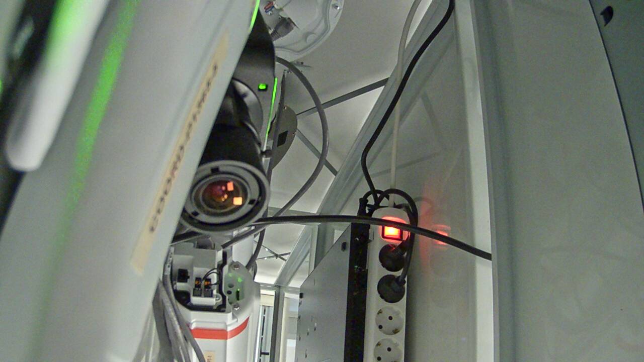
Metadata via RTSP
Generally speaking, metadata in Axis devices consists of three different types: event, PTZ, and analytics. The metadata is encapsulated in an RTP/TCP stream that can be requested from the Axis device. We discuss the different types of metadata in the sections below. See also the white paper Unlocking the power of scene metadata.
Event and PTZ metadata
As of AXIS OS 5.40, Axis devices have been capable of sending event and PTZ metadata to a receiving 3rd party application, such as a video management system. The event and PTZ metadata is sent only when the state of the Axis device changes, meaning that the data stream is not constant. Some common examples of event metadata are the manual trigger, virtual inputs, and storage-related triggers. For mechanical PTZ cameras, the metadata includes positioning data as well as information on when a PTZ preset is reached or when the device moves.
Analytics metadata
Analytics-related metadata has been available since AXIS OS 9.50. Unlike the event and PTZ metadata stream described above, analytics metadata is streamed constantly from the Axis device to receiving clients, even if nothing happens in the scene. Typical examples of analytics metadata are motion or object detection coming from Axis analytics applications (ACAPs) such as AXIS Video Motion Detection. As of AXIS OS 10.10, AXIS Object Analytics changed from using the Axis Object Analytics engine to AXIS Analytics Scene Description. For more information, click here. You can also find out more about AXIS Object Analytics here.
A sample network trace that illustrates how metadata information is transferred can be downloaded here. You can use Wireshark to search for specific metadata events within the RTP/TCP stream, as illustrated in the screenshot below.
In the following sections you can read more about how to get started and perform further testing.
Receiving metadata via RTSP
Metadata information can be fetched from an Axis device by opening an RTSP stream that uses the TCP transport protocol. The AXIS Metadata Monitor can be used as a simple test tool to request metadata from an Axis device. You can download AXIS Metadata Monitor here and install it on a computer in order to connect to an Axis device in your network. Below is a sample list of RTSP requests for receiving metadata events from an Axis device.
| RTSP request | Description |
|---|---|
| rtsp://ip-address/axis-media/media.amp?event=on&video=0 | Event metadata excluding video stream. |
| rtsp://ip-address/axis-media/media.amp?event=on&analytics=polygon&video=0 | Event and video analytics metadata excluding video stream. |
| rtsp://ip-address/axis-media/media.amp?event=on&analytics=polygon&ptz=all&video=0 | Event, video analytics and PTZ metadata excluding video stream. |
| rtsp://ip-address/axis-media/media.amp?event=on | Event metadata including video stream. |
| rtsp://ip-address/axis-media/media.amp?event=on&video=1&audio=1 | Event metadata including video and audio stream. |
| rtsp://ip-address/axis-media/media.amp?event=on&video=0&audio=1 | Event metadata excluding video, but including audio stream. |
| rtsp://ip-address/axis-media/media.amp?event=on&video=0&eventtopic=axis:CameraApplicationPlatform/VMD/Camera1ProfileANY | Event metadata excluding video and filtering only for AXIS Video Motion Detection (VMD) alarms. |
| rtsp://ip-address/axis-media/media.amp?event=on&video=0&eventtopic=onvif:Device/axis:IO/VirtualPort | Event metadata excluding video and filtering only for the manual trigger event. |
Additional parameters such as camera=2 to camera=9 can be added to the above requests to e.g. receive metadata events from a different video channel. This is useful when the Axis device supports more than one video source or if different view areas are configured. In the example below we use AXIS Metadata Monitor to connect to an Axis device by using one of the RTSP requests above together with the IP address of the Axis device and its access credentials.
As you can see, the Axis device is responding to the RTSP request with all its currently available metadata information and states. A simple way of testing incoming metadata events is to toggle the manual triggers in the web interface.
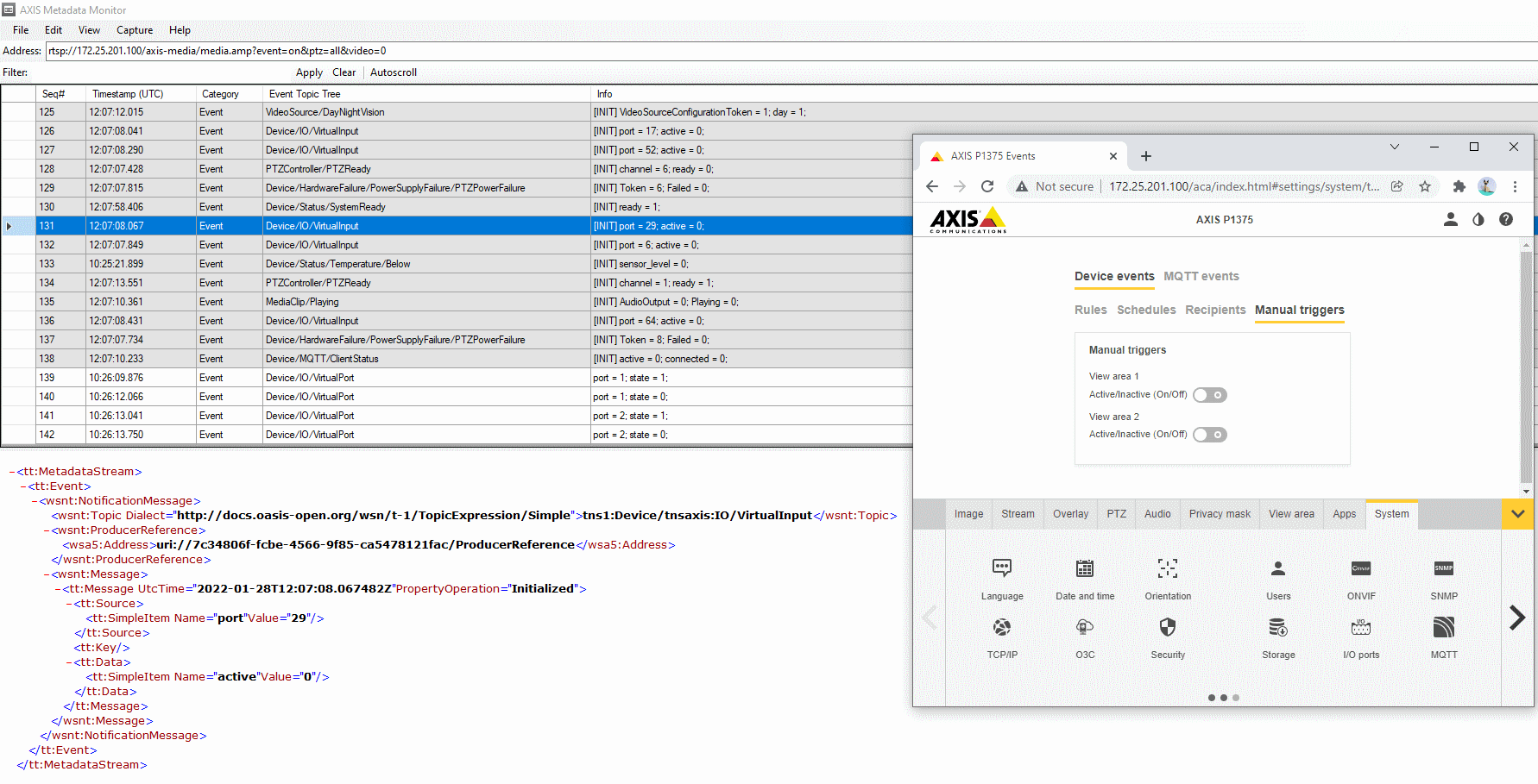
Another option would be to use one of the pre-installed Axis analytics applications (ACAPs), such as AXIS Video Motion Detection, to trigger a test alarm or motion in front of the Axis device in order to get motion detection/analytics based metadata events.
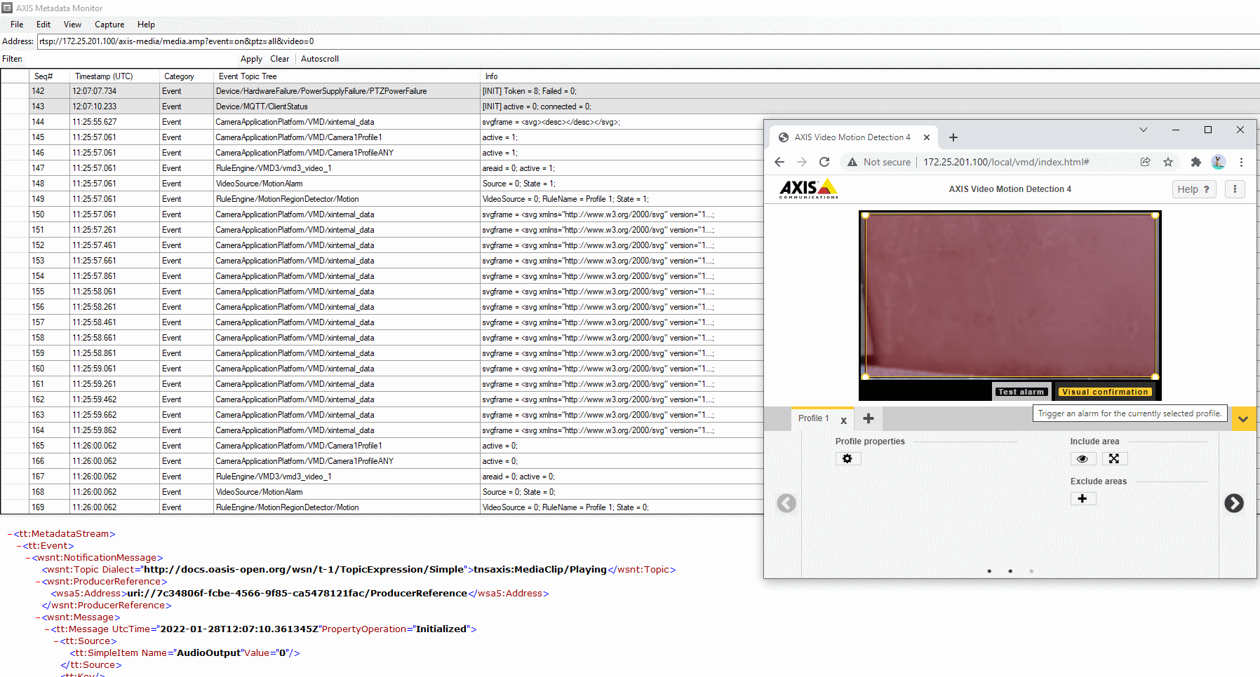
Examples of metadata events
Further down you will find a (non-complete) table of common metadata and device events available in Axis devices. The type and amount of events that are available depend on the hardware/software capabilities of the Axis device, some of which are:
Mechanical and/or digital PTZ
Mechanical and/or digital I/O
Audio in and audio out capabilities
Axis analytics applications (ACAPs) such as AXIS Video Motion Detection, AXIS Object Analytics etc.
3rd party applications
| Metadata/event category | Topic | Possible states |
|---|---|---|
| PTZ | PTZController/PTZPresets/Channel1 | on_preset=0/1 |
| PTZ | PTZController/Move/Channel1 | is_moving=0/1 |
| PTZ | PTZController/PTZReady | ready=0/1 |
| PTZ | PTZController/ControlQueue | queue_owner=userx |
| I/O | Device/IO/VirtualInput | actve=0/1 |
| I/O | Device/IO/Port | state=0/1 |
| I/O | Device/Trigger/DigitalInput | state=0/1 |
| Temperature | Device/Status/Temperature/Above | sensorlevel=0/1 |
| Temperature | Device/Status/Temperature/Below | sensorlevel=0/1 |
| Temperature | Device/Status/Temperature/Inside | sensorlevel=0/1 |
| Temperature | Device/Status/Temperature/Above_and_Below | sensorlevel=0/1 |
| Temperature | Device/Heater/Status | running=0/1 |
| System | Device/Status/SystemReady | ready=0/1 |
| Hardware | Device/Sensor/PIR | state=0/1 |
| Audio | Device/RingPowerLimitExceeded | limit_exceeded=0/1 |
| Hardware | Device/Network/Lost | lost=0/1 |
| Hardware | Device/Network/BlockedIP | address = x.x.x.x |
| Hardware | Device/Casing/Open | open=0/1 |
| Storage | Storage/Disruption | disruption=0/1 |
| Storage | Storage/Recording | recording=0/1 |
| Hardware | Device/HardwareFailure/StorageFailure | disruption=0/1 |
| Hardware | Device/HardwareFailure/FanFailure | failure=0/1 |
| Hardware | LightControl/LightStatusChanged/Status | state=off/on |
| Video | VideoSource/LiveStreamAccessed | day=0/1 |
| Video | VideoSource/DayNightVision | accessed=0/1 |
| Video | VideoSource/ABR | abr_error=0/1 |
| Audio | AudioSource/TriggerLevel | triggered=0/1 |
| Audio | AudioControl/DigitalSignalStatus | signal_status=signal/no signal |
| Video | VideoEncoder/Connections | connected=0/1 |
| Video | VideoSource/Connections | connected=0/1 |
| Analytics | VideoAnalytics/Tampering | active=0/1 |
| Analytics | VideoAnalytics/MotionDetection | motion=0/1 |
| Analytics | CameraApplicationPlatform/VMD | active=0/1 |
| Analytics | CameraApplicationPlatform/MotionGuard | active=0/1 |
| Analytics | CameraApplicationPlatform/LoiteringGuard | active=0/1 |
| Analytics | CameraApplicationPlatform/FenceGuard | active=0/1 |
Axis analytics metadata configuration
From AXIS OS 10.11 and onwards, it's possible to choose dedicated analytics producers within the Axis device or to have multiple analytics metadata producers enabled simultaneously. In the backend, the Axis device can either be configured to produce analytics metadata by using the "Axis video motion tracker", which is the commonly known producer used since AXIS OS 9.50, or by using the newer "Axis object analytics" producer. The "Axis object analytics" producer offers some valuable extensions and more information with regards to analytics data, such as more detailed object classification (human faces, license plate numbers, etc.) that are useful in forensic search scenarios.
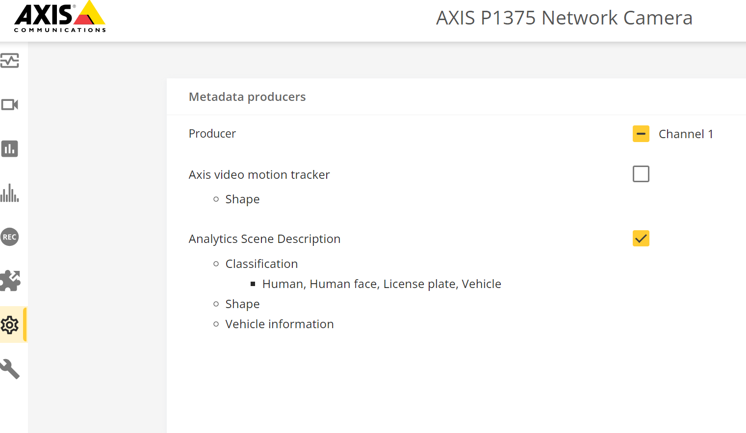
Metadata via WebSocket
From AXIS OS 10.11 and onwards it's possible to subscribe to the metadata stream using the (secure) WebSocket protocol. For more general information about Axis metadata streaming, see Metadata via RTSP.
In the below example we’re using the WebSocket King extension for the Google Chrome browser, however there are many other clients available supporting WebSocket communication.
Step 1: Login to your Axis device using the browser the extension has been installed to.
Step 2: In the WebSocket King extension, connect to:
HTTP: ws://IP/vapix/ws-data-stream?sources=events
HTTPS: wss://IP/vapix/ws-data-stream?sources=events
Note that if you’re using HTTPS in step 1, you will need to use the same for the connection in the WebSocket King extension.
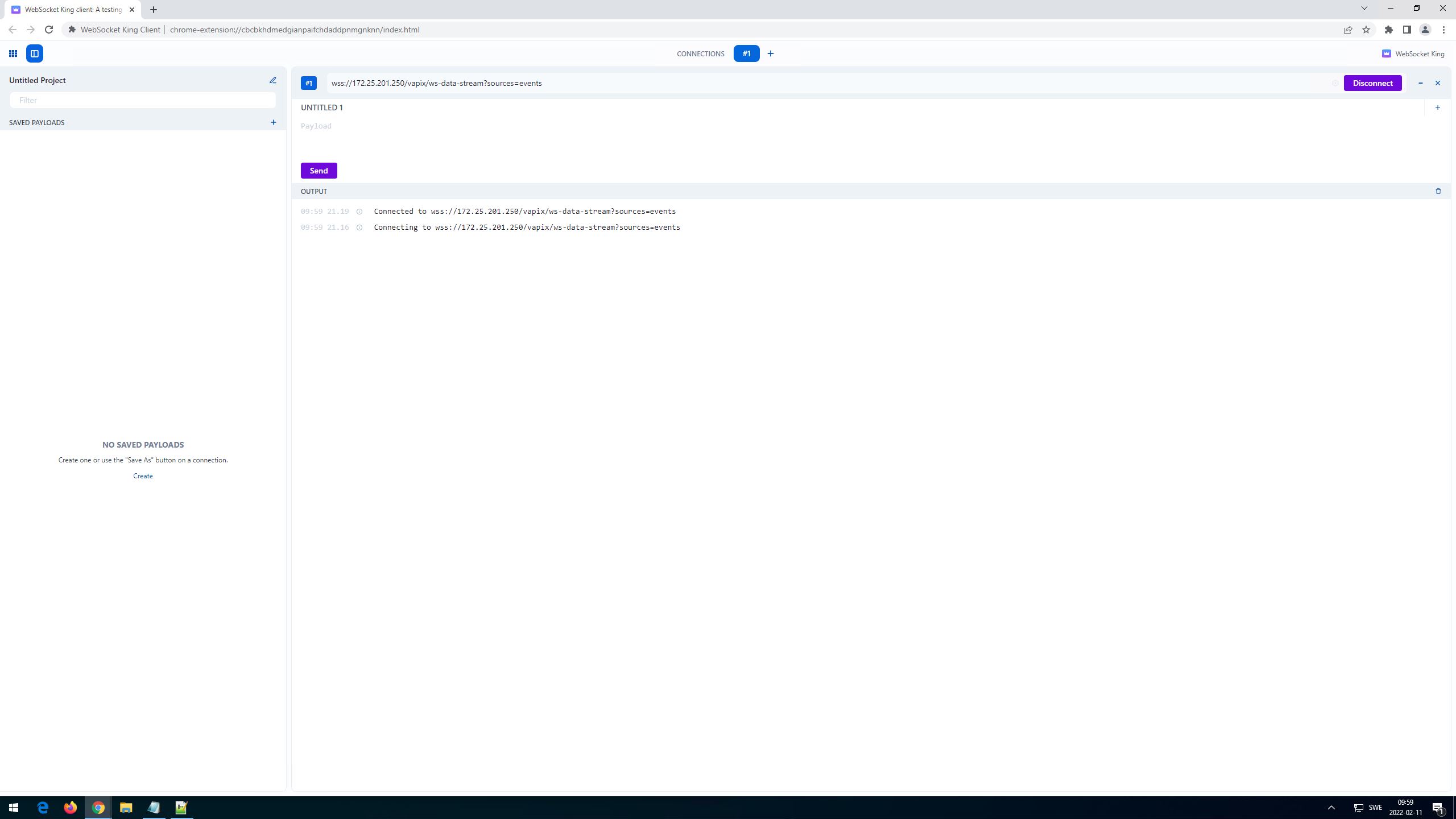
Step 3: Send the following request to receive all events:
{
  "apiVersion": "1.0",
  "method": "events:configure",
  "params": {
    "eventFilterList":[
      {
        "topicFilter":""
      }
    ]
  }
}
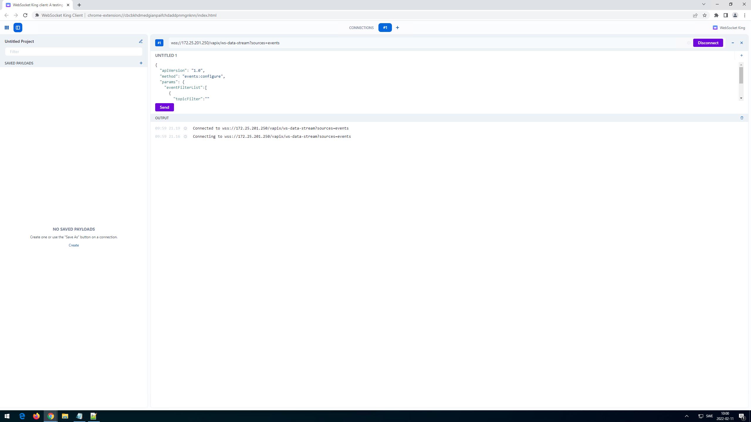
It's also possible to subscribe to a specific topicFilter, for example: "topicFilter":"tns1:Device/tnsaxis:IO/VirtualInput". Go to Examples of metadata events for more topic examples. Furthermore it's possible to subscribe to a specific port. Below you can see an example of virtual input port 47.
{
  "apiVersion": "1.0",
  "method": "events:configure",
  "params": {
    "eventFilterList":[
      {
        "topicFilter":"tns1:Device/tnsaxis:IO/VirtualInput",
        "contentFilter":"boolean(//SimpleItem[@Name=\"port\" and @Value=\"47\"])"
      }
    ]
  }
}
Step 4: Events will start streaming based on the set filter.
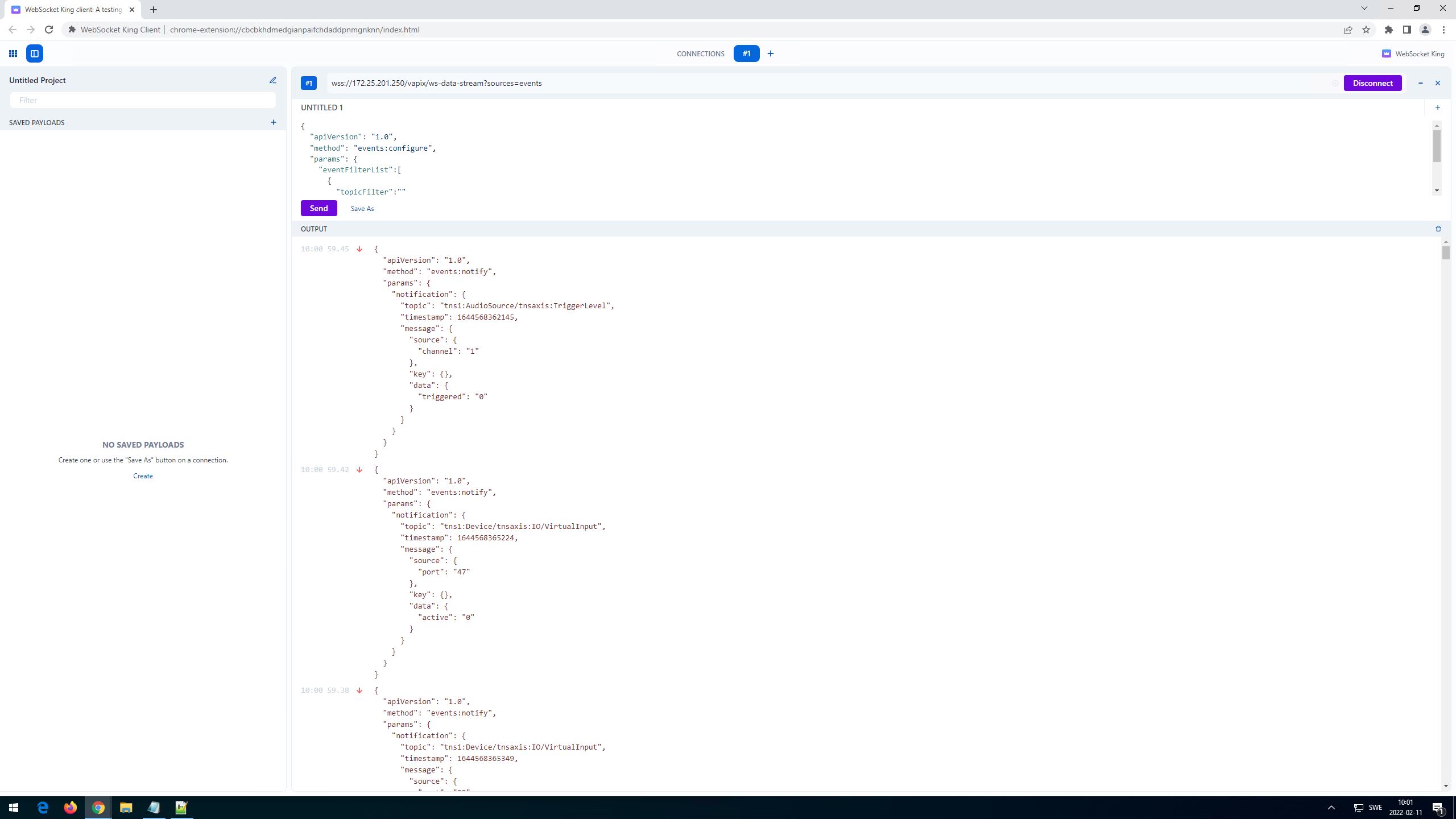
Step 5: Below is an example of toggling the manual trigger on the Axis device, which is reflected in the metadata stream.
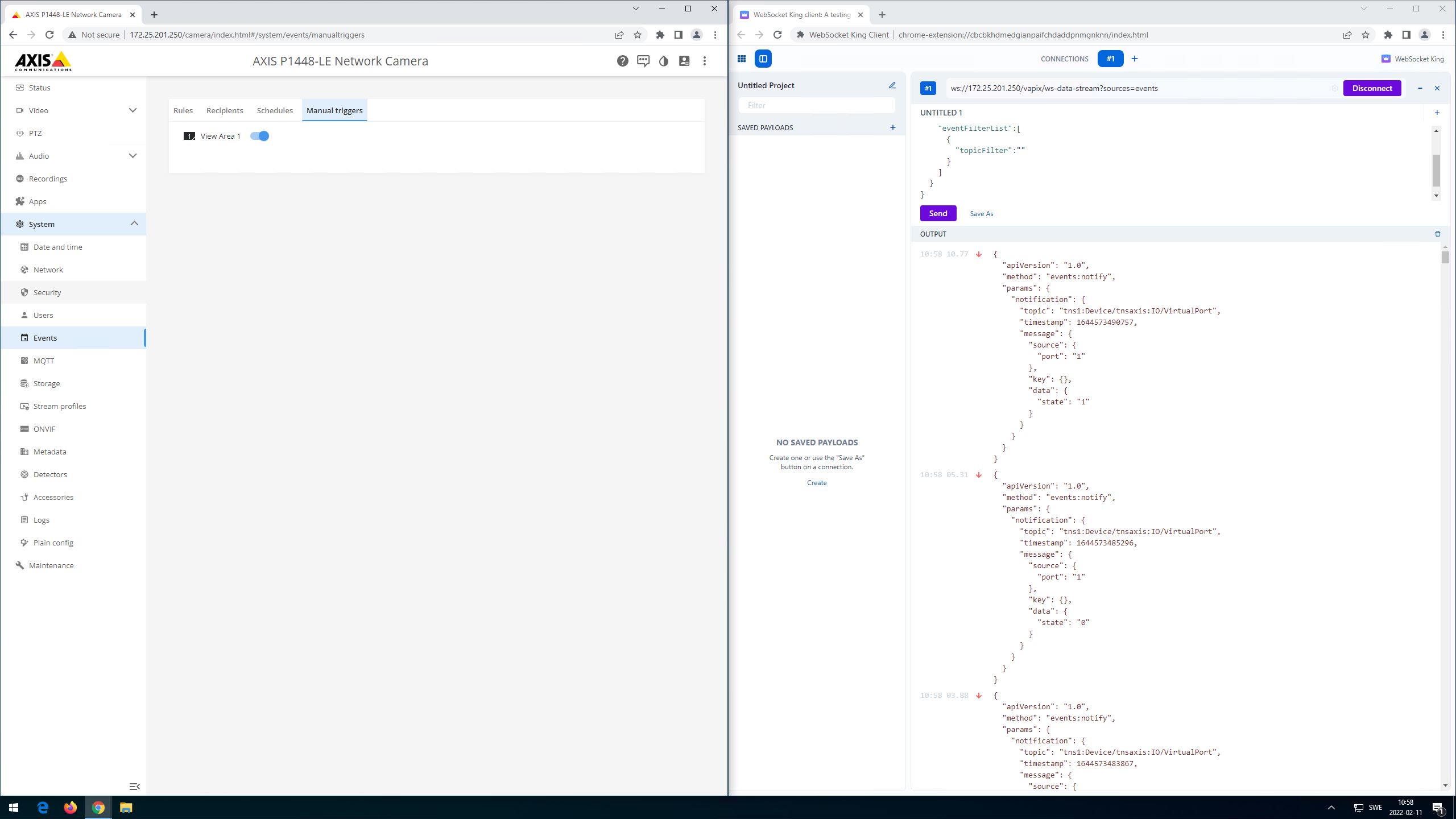
Network protocols
Commonly used network ports
In this section you can read about commonly used network ports used by an Axis device for different services over the network.
Enabled by default
| Protocol | Port | Transport | Comments |
|---|---|---|---|
| 802.1X | N/A** | EAP | IEEE 802.1X network authentication |
| Bonjour | 5353 | UDP | Used by 3rd party applications to discover the Axis device via mDNS discovery protocol (Bonjour) |
| CDP | N/A** | CDP | Used by network infrastructure to identify the Axis device or to provide PoE negotation capabilities. |
| HTTP | 80 | TCP | General HTTP traffic such as web interface access, VAPIX and ONVIF API interface or Edge-to-edge communication. |
| HTTPS | 443 | TCP | General HTTPS traffic such as web interface access, VAPIX and ONVIF API interface or Edge-to-edge communication. |
| LLDP | N/A** | LLDP | Used by network infrastructure to identify the Axis device or to provide PoE negotation capabilities. |
| RTP | Ephemeral port range* | UDP | Used by the Axis device for video/audio streaming |
| RTSP | 554 | UDP | Used by the Axis device for video/audio streaming |
| UPnP | 49152 | TCP | Used by 3rd party applications to discover the Axis device via UPnP discovery protocol |
| SSDP | 1900 | UDP | Used by 3rd party applications to discover the Axis device via SSDP (UPnP) |
| WS-Discovery | 3702 | UDP | Used by 3rd party applications to discover the Axis device via WS-Discovery protocol (ONVIF) |
Configuration dependent
| Protocol | Port | Transport | Comments |
| ICMP/PING | N/A** | ICMP | General OSI layer 3 communication |
| FTP | 21 | TCP | FTP access to Axis device |
| SSH | 22 | TCP | SSH access to Axis device |
| Telnet | 23 | TCP | Telnet access to Axis device |
| DNS | 53 | UDP | Used by the Axis device to resolve IP address to hostnames |
| NTP | 123 | UDP | Used by the Axis device to synchronize time |
| NTS | 4460 | TCP | Used by the Axis device to synchronize time. From AXIS OS 11.1 |
| SNMP | 161 | UDP/TCP | Used by the Axis device to send SNMP communication |
| SNMP (Traps) | 162 | UDP/TCP | Used by the Axis device to send SNMP communication |
| Syslog | 514 | UDP | Used by the Axis device to send log messages to a remote syslog |
| Syslog | 601 | TCP | Used by the Axis device to send log messages to a remote syslog |
| Syslog | 6514 | TCP | Used by the Axis device to send log messages to a remote syslog via SSL/TLS |
| MQTT | 1883 | TCP | Used by the Axis device to send device events to a MQTT broker |
| MQTT | 8883 | TCP | Used by the Axis device to send device events to a MQTT broker via websockets |
| RTSPS | 322 | UDP | Used by the Axis device for encrypted video streaming (RTSPS/SRTP) |
| SMB | 445 | TCP | Used by the Axis device for edge recording to a remote network storage |
| O3C | 3128 | TCP | Used by the Axis device for O3C-related cloud communication |
| SOCKS | 1080 | TCP | Used by the Axis device for SOCKS-proxy network communication |
| SFTP | 22 | TCP | Used by the Axis device to send data via SFTP in an event rule |
| Action rule: email | Ephemeral port range* | TCP | Used by the Axis device to send images/videos via mail notification in an event rule |
| Action rule: TCP notification | Ephemeral port range* | TCP | Used by the Axis device to send notifications via TCP in an event rule |
| Action rule: image/video upload | Ephemeral port range* | TCP | Used by the Axis device to send images/videos via HTTP(S) in an event rule |
| SIP | 5060 | UDP/TCP | Used by the Axis device to send SIP communication |
| SIP | 5061 | UDP/TCP | Used by the Axis device to send SIP communication via TLS |
*Allocated automatically within a predefined range of port numbers according to RFC 6056. More information can be found here.
**There is no TCP or UDP port number associated with this network traffic as these are associated with the transport layer above.
***IEEE 802.1X is only enabled by default on Axis Device ID capable devices.
To find out which Axis product that support Axis Device ID, please go to Axis product selector and select Axis device ID under Cybersecurity.
NTP and NTS (Network Time Sync)
Network Time Protocol (NTP)
Network Time Protocol is used to synchronize computer clocks on the Internet or in local networks. Version 4 (NTPv4) is the current version and is described by RFC 5904. It's fully compatible with NTPv3 and all previous versions and is designed to support the IPv6 protocol and dynamic server discovery. NTP is utilizing UDP as a transport protocol via port 123, which means that package delivery cannot be guaranteed.
Axis devices use two implementations as their current platform, depending on the AXIS OS version.
| AXIS OS | Implementation |
| < 11.0 | OpenNTPD |
| ≥ 11.0 | Chrony |
Chrony is a newer implementation of the Network Time Protocol compared with OpenNTPD. It can perform well in challenging situations where the network is congested or the network connection is intermittent. Chrony can synchronize the system faster and quickly adapt to sudden clock rate changes. Additionally, Chrony supports Network Time Security (NTS) (RFC 8915) so that the time the device gets comes from a trusted source. You can find more information about Chrony here.
NTP uses a hierarchical structure where several NTP servers operating on different levels and accuracy (=stratum) are synced against each other to provide accurate time syncs to network devices. To do so, an NTP server in the network that provides time to local network devices should always sync to one or more NTP servers higher up in the hierarchy to avoid time-fluctuation and increased time accuracy. However, it's possible to operate an NTP server locally in a network in a standalone mode if no other NTP servers are available. More information about how the NTP protocol works can be obtained from public sources such as Wikipedia.
Network Time Security (NTS)
Axis devices with AXIS OS 11.1 or higher support Network Time Security. NTS allows the devices to get time from a trusted source. NTS is a mechanism for using Transport Layer Security (TLS) and Authenticated Encryption with Associated Data (AEAD) to provide cryptographic security for the client-server mode of the NTP.
NTS consists of 2 protocols:
NTS Key Exchange (KE): Exchange the necessary keys between the NTP client and server via Transport Layer Security (TLS). Once key exchanges are done, the TLS channel will be closed. The NTP client also knows which NTP server to query.
NTP Authentication: The NTP client queries the time to the NTP server. Both parties authenticate NTP time synchronization packets using the results of the TLS handshake.
More public information about NTS can be found here.
Sync process
OpenNTPD
The following sections illustrate the steps taken during a complete NTP synchronization while using OpenNTPD. This network trace can be used as a reference for below steps and shows a complete NTP synchronization from the first phase until the Axis device is in full NTP sync with the configured NTP server.
Phase 1: It starts with the initial time query.
The very first time-sync from an Axis device to an NTP server is a "universal sync" which means that any time provided by the NTP server will be taken by the Axis device as system time. Phase 1 is usually initiated when configuring the Axis device to sync against an NTP server (enable NTP), when the Axis device is restarted or when an upgrade is initiated that also results in a restart of the Axis device.Phase 2: After phase 1 follows a consolidation phase, where a number of time-sync requests from the Axis device against the NTP server are performed in between a 6 s – 60 s interval + 10 % randomization apart in order to align further with the NTP server to assure a close time-sync. The number of time-syncs vary depending on accuracy and trust according to the NTP protocol, but 5-15 time-syncs are usually needed.
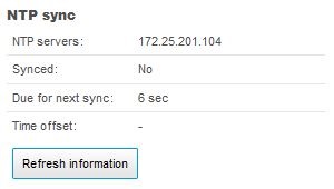
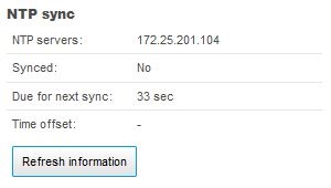
Phase 3: Phase 3 is considered the usual operation mode. The query interval will stabilize after phase 2 between 30 - 1500 s + 10 % randomization apart. In case the time difference increases during normal operation mode, the device will shorten the interval to sync more often in order to compensate for this. And if the time drift is very small, the intervals between two syncs will be larger. Note that the sync state is changing to "Yes", which indicates that the Axis device is in good time-sync with the configured NTP server.
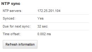
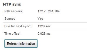
Chrony
The following sections illustrate the steps taken during a complete NTP synchronization while using Chrony.
Phase 1: Phase 1 starts with the initial time query. Chronyd will begin with a burst of 4-8 requests to make the clock’s first update sooner. Once it gets the reply from the NTP server, it calculates the time difference between the current system time against the timestamp from the NTP server. In our implementation, we set the Chrony to step the system clock if the adjustment is larger than 0.1 seconds, but only in the first clock update since chrony was started. If the time difference is less than 0.1s, the Chrony will enter slew mode. The max rate that Chrony allowed to slew the time is set to 83333.333ppm (1/12s). Once the time is synchronized, you will see “yes” on the webpage.
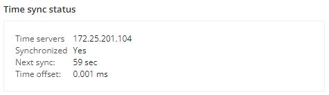
Phase 2: Phase 2 is considered the usual operation mode. Once the time is synchronized, the general query polling interval to the NTP server is set to 64 seconds.Most of the Axis devices have a built-in real-time clock (RTC). The system will copy the clock from the RTC on the boot. To maintain the accuracy of the RTC, we enabled chronyd to copy the system time to the RTC every 11 minutes. Please be aware that chronyd will not track RTC drift.One of the main activities of the chronyd program is to work out the rate at which the system clock gains or loses time relative to real time. Whenever chronyd computes a new value of the gain or loss rate, it will record the value at /var/lib/chrony/drift. This can also help stabilize the initial synchronization on the next start.
NTS Sync process
To configure NTS, go to System > Date and time, and select Automatic date and time (manual NTS KE servers).
You can either input the IP address of the NTP KE servers or the hostname (make sure the DNS server is properly configured). Here is an example of successful time sync via NTS:
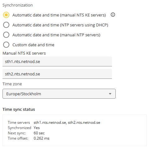
The behaviors of the time sync process are almost identical to those we mentioned in the above Chrony sync process. Here we mainly focus on the key exchange and secure part.
Phase 1
The Chrony client starts communicating with the KE server by establishing a TLS channel. That follows the key exchange. In the key exchange process, the client receives secret keys and cookies to be used later. The cookies contain secret keys only understood by the NTP server. The KE server also notifies the client which NTP server to query. Once the exchange is done, the TLS channel will be terminated.Phase 2
The Chrony client directly contacts the NTP server. It encrypts the query by the key it gets from phase 1. In that query, a cookie is also included. Once the server receives the query, it knows how to read the query. The server will respond to the client with a signed query. The client validates the signature in the incoming packet and then sets the time knowing it was sent from the correct server.
Common log messages
The following common log messages from Axis devices can be seen during NTP/NTS time-sync operations as well as during certain error conditions, e.g. if the NTP/NTS server is not operating correctly or cannot be reached. The log messages and their explanations provide a great detail of information on how the NTP/NTS protocol is working in practice. Plus, it's good to get an understanding of the log messages when troubleshooting NTP/NTS protocol related issues.
| Situation | Clock | NTP log message | Explanation |
| Sync | NTPd Linux system clock | ntpd[21696]: reply from 192.168.255.29: offset -0.879648 delay 0.000313, next query 32s | This is a common log message indicating the offset, delay and when the next time-sync is going to be performed.
|
| No reply | NTPd Linux system clock | ntpd[21696]: no reply from 192.168.255.29 received in time, next query 30s | The Axis device's NTPd process could not reach the NTP server on the network layer 2 and/or 3. |
| No reply | NTPd Linux system clock | ntpd[21696]: no reply from 192.168.255.29 received in time, retransmit query 32s | The Axis device's NTPd process could not reach the NTP server on the network layer 2 and/or 3. |
| Negative delay | NTPd Linux system clock | ntpd[21696]: reply from 192.168.255.29: negative delay -0.000471s, next query 3213s | A state where the Axis device's NTPd process considers the NTP server in an erroneous state. Most likely the time has drifted significantly between the two network interfaces of the Axis device and the NTP server under a very short period of time and the "delay" can no longer be calculated correctly. No sync will take place for a longer period of time. |
| NTP server denies sync | NTPd Linux system clock | ntpd[21696]: reply from 192.168.255.29: not synced (alarm), next query 3196s | The log message indicates that the NTP server itself denies to synchronize the NTPd process of the Axis device because it considers itself not synchronized to its (lower stratum) NTP server. It's a message that is sent from the NTP server. No sync will take place for a longer period of time. |
| System clock synced | NTPd Linux system clock | ntpd[21696]: clock is now synced | The log message means that the NTPd process of the Axis device considers itself synced to the NTP server. This will cause the time-sync interval to be set to larger sync intervals since less syncs are needed. Directly after the sync state is reached, the RTC clock of the Axis device can be updated by the NTPd process. |
| System clock unsynced | NTPd Linux system clock | ntpd[21696]: clock is now unsynced | The log message means that the NTPd process of the Axis device is not considering itself in sync with the NTP server. This state should not last long. When in this state, no RTC clock updates can be performed. If the logs indicate that the camera is in an unsynced state for many hours or days, it means that the NTP server is drifting faster than the Axis device’s NTPd process can account and compensate for. |
| NTP server reachable | NTPd Linux system clock | ntpd[21696]: peer 172.27.0.41 now valid | The log message indicates that the NTPd process of the Axis device could successfully verify the NTP server(s) integrity it's supposed to sync to. |
| NTPd drift file | NTPd Linux system clock | 1323.2313 | This value is in ppm (=microseconds) and indicates the amount of drift of the Linux system time that needs to be considered and compensated for by the Axis device's NTPd process. Note that this has nothing to do with the time drift that can occur on the RTC clock. Can be obtained via /var/lib/openntpd/db/ntpd.drift. |
| RTC clock is set | RTC clock | ntpd[21696]: set local clock to Tue May 29 08:34:21 CEST 2018 (offset 0.000168s) | The log message indicates that the NTPd process of the Axis device is updating the RTC clock for the first time after it considered itself in good NTP sync towards the NTP server. |
| RTC clock is updated | RTC clock | ntpd[21696]: adjusting local clock. The current time diff is now -76.421369s | When the NTPd process of the Axis device is in "Clock is now in sync" state, the RTC clock receives updates. The "current time diff" represents the time difference between NTPd Linux system clock and RTC clock. |
| Sync | Chronyd Linux system clock | chronyd[19610]: chronyd version 4.2 starting (+CMDMON +NTP +REFCLOCK +RTC +PRIVDROP -SCFILTER -SIGND +ASYNCDNS +NTS -SECHASH +IPV6 +DEBUG) | The log message indicates that the chronyd process of the Axis device is up and running. This log can be seen when you set the devices to sync the time with NTP server. |
| Sync | Chronyd Linux system clock | chronyd[19610]: Selected source 194.58.207.79 (sth1.nts.netnod.se) chronyd[18836]: Selected source 172.20.45.119 | The log message means that the chronyd process of the Axis device successfully verifies the NTP server and selects the NTP server as the time source. |
| Sync | Chronyd Linux system clock | chronyd[17156]: System clock wrong by 250.930199 seconds chronyd[17156]: System clock was stepped by 250.930199 seconds scheduled[900]: Time was manipulated! | This log can be seen when the chronyd process of the Axis device gets the time from the NTP server and adjust its time to the correct one. |
| Chronyd drift file | Chronyd Linux system clock | chronyd[19610]: Frequency 1.637 +/- 13.841 ppm read from /var/lib/chrony/drift | The log message can be seen when chronyd process just started. When chronyd computes a new value of the rate at which the system clock gains or loses time relative to real time, it records it here /var/lib/chrony/drift. This allows chronyd to begin compensating the system clock at that rate whenever it is restarted. The first is the rate at which the system clock gains or loses time, expressed in parts per million, with gains positive. The second is an estimate of the error bound around the first value in which the true rate actually lies. |
| System clock unsynced | Chronyd Linux system clock | chronyd[2235]: Can't synchronise: no selectable sources | This log can be seen when the chronyd process of the Axis device gets a new update from the NTP server. However, the time varies too much and therefore the Axis device decide not to trust it. In the device’s webpage, you will see the “Synchronized” status becomes No. |
| System clock unsynced | Chronyd Linux system clock | time-service: No request received, starting termination process systemd[1]: systemd-timedated.service: Deactivated successfully. systemd[1]: time.service: Deactivated successfully. | This log will show when the chronyd process of the Axis device doesn’t get a reply from the NTP server. |
| NTS | Chronyd Linux system clock | Source 194.58.207.69 changed to 194.58.207.79 (sth1.nts.netnod.se) | This log will show when the chronyd process of the Axis device is redirecting itself from a KE server to an NTP server. |
| NTS Key Exchange | Chronyd Linux system clock | chronyd[7694]: TLS handshake with 194.58.207.69:4460 (sth1.nts.netnod.se) failed : Error in the certificate verification. The certificate is NOT trusted. The certificate issuer is unknown. | This log will show when using NTS. The system doesn’t trust the KE Server. Please ensure the KE server’s CA certificate is uploaded into the Axis device. |
| NTS Key Exchange | Chronyd Linux system clock | chronyd[29971]: NTS-KE session with 194.58.207.10:4460 (194.58.207.10) timed out | This log indicates that the chronyd process of the Axis device cannot establish an NTS-KE session with the servers. Please check the configuration and network settings to see if anything is blocked. |
| NTS Key Exchange | Chronyd Linux system clock | ntpconfd: No NTS servers available! | This log indicates that the NTS server is not set correctly in the device webpage. |
| Stop NTP | Chronyd Linux system clock | systemd[1]: Stopping NTP client/server... systemd[1]: Started Time & Date Service. chronyd[12200]: chronyd exiting systemd[1]: chronyd.service: Deactivated successfully. systemd[1]: Stopped NTP client/server. | This log will be shown when you switch to manual date and time instead of NTP. |
Multiple time servers
With AXIS OS 9.40.1 or higher it's possible to configure a secondary NTP server in the web interface as well as up to five NTP servers via the VAPIX Time API. The device tries to synchronize with all servers that are configured. With the VAPIX Time API it's possible to configure up to 5 NTP server URLs. Additionally, one NTP server URL can resolve to many addresses, but only one "valid" server per URL is used for synchronization. So if you configure...
pool.ntp.axis.com AND 0.ntp.com where pool.ntp.axis.com resolves as three addresses [146.76.54.5, 146.76.54.56, 146.76.54.5] and 0.ntp.com resolves to 45.32.76.99
...the actual NTP servers that will be used are ONE valid and reachable address of the first URL and ONE valid and reachable address of the second URL:
(146.76.54.5 OR 146.76.54.56 OR 146.76.54.5) AND 45.32.76.99
The NTP algorithm determines which NTP server to use from the first pool.
With AXIS OS 11.0 or higher, when setting multiple NTP sources, Chrony tries to select the most accurate and stable sources for the synchronization of the system clock. This also applies when setting multiple NTS servers.
External time servers
Axis public NTP server
Axis public NTP server is ntp.axis.com, to which cameras connected to the internet can sync its time.
Meinberg NTP server
Meinberg has its own standalone NTP server software that can be installed on Microsoft Windows OS with the possibility to sync against other NTP servers. It also has a standalone operation mode, ideal and simple for standalone environments without network connection to the outside.
Netnod NTS server
Netnod’s NTP service, funded by the PTS, is available for free to anyone. Netnod currently provides the following NTS servers.
nts.netnod.se
sth1.nts.netnod.se
sth2.nts.netnod.se
Windows NTP server
By following these steps, it's possible to configure your local Windows system as an NTP server.
Note that Windows by default will have a lower NTP time accuracy as well as larger sync intervals, which may not be optimal for good time accuracy.
For Chrony, a common issue with Windows NTP servers is that they report a very large root dispersion (e.g., three seconds or more), which causes chronyd to ignore the server for being too inaccurate.
It's recommended to configure the Windows NTP server with more strict and accurate time accuracy and sync intervals. See the following guides for more information on this:
If you use Windows as the NTP server for an offline installation, the Windows NTP server may use the local CMOS clock time. By default, it will report a root dispersion of 10 seconds. See the following guides for more information on how to change this value:
Troubleshooting
Peer clock stratum unspecified or invalid (0)
| Implementation | Explanation |
| OpenNTPD | The Axis device will not accept timestamps if the local NTP server is not synced with high layer NTP servers (Higher NTP hierarchy) as no reliable timestamps are provided. |
| Chrony | The chronyd process of the Axis device will only synchronize with an NTP server at Stratum 15 or above. |
What time is the Axis device sending?
While debugging NTP-related network issues, it can be observed that the Axis device is transmitting a random 64-bit time to the NTP server in order to mitigate the risk of cybersecurity attacks. This does not have any impact on the performance or quality of the NTP time sync itself since the NTP server will still respond with a valid time stamp which the Axis device will apply to its time.
Maximum time difference
| Implementation | Explanation |
| OpenNTPD | Time differences between the Axis device and the NTP server that are larger than 2.145 s (35.75 min / 0.5 h) will result in there being no more time syncs. The reason is that the Axis device will assume that the time coming from the NTP server has changed too drastically and therefore considers the NTP server unreliable. It's recommended to check if the NTP server is functioning correctly and to reconfigure the Axis device to sync with the NTP server again to initiate a new time sync procedure. |
Counteract clock drifting
If the system clock has a significant drift, the Axis device's clock will never achieve a close enough offset to the NTP server. However, the system clock should not drift at a rate of that magnitude.
| Implementation | Explanation |
| OpenNTPD | The NTP client can adjust the system clock to 500 ppm (part per million) at most. It can counteract a clock drift of 1.8 seconds per hour. |
| Chrony | The Chrony client can adjust the system clock to 83333.333 ppm (part per million) at most. In theory, it can, counteract a clock drift of 300 seconds per hour. |
Precision Time Protocol
Precision Time Protocol (PTP) is a network protocol that ensures highly accurate time synchronization between devices (clocks) connected over Ethernet or IP networks. While NTP can achieve millisecond-level accuracy, PTP can achieve nanosecond accuracy.
PTP uses master-client architecture, where the master lock is the time source, and the client clock syncs its time to the master clock.
There are four types of clocks defined by PTP:
An Ordinary Clock has a single interface that runs PTP. This clock can act as either master or client. The end-device is usually an ordinary clock.
A Boundary Clock has two or more interfaces running PTP. This clock synchronizes time with an upstream master, and distributes the time to downstream clients.
A Transparent Clock doesn’t act as either master or client, but simply forwards PTP messages.
A Grandmaster Clock is the most accurate clock in the network, to which all others will synchronize.
PTP relies on TAI (International Atomic Time) for synchronization, ensuring high precision and continuity, as TAI is unaffected by leap seconds. Meanwhile, the Linux kernel's System Time operates on UTC (Coordinated Universal Time), which the system converts to the user's local time based on the configured time zone for display and application purposes. TAI currently leads UTC by 37 seconds.
We added support for PTP as of AXIS OS 12.7 Our implementation leverages the IEEE 1588 PTPv2 default profile with hardware time-stamping, which requires a compatible Network Interface Card (NIC) that handles the timestamp information directly, with no software processing. This makes for much higher accuracy. At the time of writing, PTP is only supported on devices with ARTPEC-8, ARTPEC-9, 8M-MINI, 8M-NANO, and 6SX chipsets.
The Best Master Clock Algorithm (BMCA) determines the best clock to act as the Grandmaster in a PTP network. It does so by examining several parameters such as priority, Clock Class, Clock Accuracy, and Clock Identity. Axis devices can act as both master and client. By default, both priority1 and priority2 are set to 248, allowing other devices in the network to be the master clock.
By default, the Axis device still uses NTP. To switch to PTP, log into the device, go to System > Time and location, and select “Automatic date and time (PTP)” under Synchronization. Note that running both NTP and PTP simultaneously is not supported. The current PTP implementation does not support software mode.
QoS (Quality of Service)
QoS provides the means to guarantee a certain level of a specified resource to selected traffic on a network. Quality can be defined as e.g. a maintained level of bandwidth, low latency, no packet losses, etc. The main benefits of a QoS aware network can be summarized as:
The ability to prioritize traffic and thus allow critical flows to be served before flows with lesser priority
Greater reliability in the network, thanks to the control of the amount of bandwidth an application may use, and thus control over bandwidth races between applications
To use QoS in a network with Axis video products the following requirements need to be met:
All network switches and routers must include support for QoS. This is important to achieve end-to-end QoS functionality
The Axis video products used must be QoS enabled
Imagine that the network in the first illustration below is an ordinary (non-QoS aware) network. In this scenario, PC1 is watching video streams from Camera 1 and Camera 2, with each streaming at 25 Mbps. Suddenly, PC2 starts a file transfer from PC3. In this scenario the file transfer will try to use the full 100 Mbps capacity between Router 1 and Router 2, whilst the video streams will try to maintain their total of 50 Mbps. We can no longer guarantee the amount of bandwidth given to the surveillance system and the video frame rate will probably be reduced. At worst, the FTP traffic will consume all the available bandwidth.
In the next illustration, the network is QoS-aware and uses the DiffServ model (see the section on QoS models). Router 1 has been configured to reserve up to 50 Mbps of the available 100 Mbps for streaming video. FTP traffic is allowed to use 20 Mbps, and HTTP and all other traffic can use a maximum of 30 Mbps. Using this division, video streams will always have the necessary bandwidth available. File transfers are considered less important and get less bandwidth, but there will still be bandwidth available for web browsing and other traffic. Note that these maximums only apply when there is congestion on the network – if there is unused bandwidth available, this can be used by any type of traffic. By using QoS we allow the network applications to co-exist on the same network, without consuming each other’s bandwidth.
Further reading
For further reading and more detailed documentation about the Quality of Service standard, see the following links:
QoS models
There are several different ways (models) of implementing QoS. Axis products use the DiffServ model, for greater scalability and flexibility. See below for more information.
The IntServ model
The IntServ model, or Integrated Services model uses a protocol called RSVP (Reservation Setup Protocol), which is used to reserve a certain traffic quality in the network. Prior to use, each application in an IntServ QoS network reserves its own resources and the router either grants or denies the request. When a reservation request is received, the routers need to find a path that can support the IntServ request and also the route that offers the best services. The major problem with this model is scalability. As the network increases in size, the connections database will grow to enormous proportions and it will be both difficult and ineffective to keep track of all reservations. Another drawback is the model’s inflexibility – the maximum amount of the resource in question that each type of traffic will ever receive is the maximum specified in the model, even if there are other unused resources available.
The DiffServ model
The Differentiated Services (DiffServ) model was introduced in 1998. It is based on two major components:
Packet marking
Router queuing disciplines
The applications in a DiffServ network mark their traffic so the router knows which service to apply to the packet. The marking is done in the IP header, by setting a field called the DSCP (Differentiated Services Codepoint). This is a 6-bit field that provides 64 different class IDs. Each DSCP value represents a QoS class, also known as a behavior aggregate. Thus, different applications can mark their own traffic with the same DSCP value. The intelligence of a DiffServ network is setup in the routers, where a particular DSCP value is mapped to a particular routing behavior. This behavior is referred to as a Per-Hop Behavior (PHB) and is implemented in the router using different queuing disciplines.
The DiffServ model abandons the concept of states as used in IntServ, and routers operate in a connectionless mode. This adds scalability to the system, since each router works independently, unaware of the network size and complexity. This model is also more flexible, as the classes of service are not strictly defined. Resources over and above the value specified as the maximum when resources are limited can be freely exploited whenever available. The main benefit of using this model in Axis products is that the products mark their own traffic, instead of letting the boundary nodes of the DiffServ domain do so. The conditioning algorithms in the boundary node cannot, for example, distinguish video over HTTP from audio over HTTP - they will only see HTTP, and probably provide a much lower level of service than actually required. To allow a node outside the DS domain to classify its own traffic:
The boundary router must be correctly configured
The camera must be set up as a trusted node
Per-Hop Behaviors (PHBs) define the router’s forwarding treatment for a certain class of traffic. Classes of traffic are also known as Behavior Aggregates (BA). Members of the BA are marked with the same DSCP value. There are four recommended PHBs defined, each mapped to one or more DSCP value.
The Default PHB: The default PHB provides the traditional best-effort service. It is represented by DSCP value 000000 (NOTE: 6-bits set to 0) and it must be available at any DiffServ router. This is the forwarding treatment applied to all non-DiffServ aware applications.
The Class-Selector PHB: To preserve backward compatibility with the old TOS field definition, the class-selector PHB defines a DSCP value of the form xxx000. The three bits represent the IP Precedence defined by a Type of Service aware network. The Class-Selector PHB ensures that DiffServ compliant nodes can coexist with IP Precedence-based nodes.
Expedited Forwarding: The Expedited Forwarding (EF) PHB provides a low loss, low latency, low jitter and guaranteed bandwidth service and can be considered the top priority behavior. Applications such as VoIP require this kind of robust service. The recommended DSCP value for EF is 101110.
Assured Forwarding: With Assured Forwarding (AF) traffic can be divided into four different classes. Each class is usually assigned a specific amount of bandwidth.
Within each class it is possible to specify three different drop precedence values. This value denotes the order in which packets will be dropped when there is congestion. A packet with a higher drop precedence will be dropped first. This gives us an AF matrix, and hence AF is often denoted AFxy, where x is the class number and y is the drop precedence. The table below shows the DSCP values recommended for the AF PHB. This gives us an AF matrix, and hence AF is often denoted AFxy, where x is the class number and y is the drop precedence. Table1.1 shows the DSCP values recommended for the AF PHB.
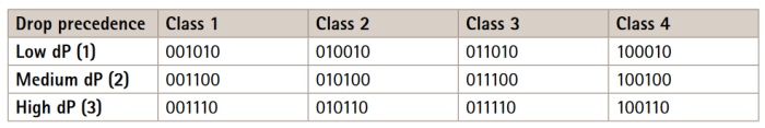
DiffServ domain
A DiffServ domain (DS-domain) is a network that has been set up according to a particular DiffServ specification, and which has a set of DSCP values mapped to certain PHBs. As each router in a DiffServ domain forwards traffic based on DSCP value mapping, we can only guarantee that we get the correct forwarding treatment within our own DS-domain. As soon as a packet leaves the domain we can no longer guarantee how other routers will map our DSCP values. The same goes for incoming traffic - we must reclassify incoming traffic to match our rules. This means we must mark the traffic with a DSCP value valid in our domain. This is usually done by looking at the packet header and setting a new DSCP value based on the source address, port numbers, etc. The marking process is called traffic conditioning and is done at the boundary nodes of the DS domain.
VLAN 802.1P model
IEEE 802.1P defines a QoS model at OSI Layer 2 (L2, Data Link). This is called CoS, Class of Service, and adds an extra 3-bit field (called user-priority) to the VLAN MAC header. This splits traffic into 8 different classes. Priority is set up in the switches, which then use different queuing disciplines to forward the packets correctly. Although the 802.1P CoS works well, it lacks scalability and cannot provide end-to-end guarantees. We cannot assume the L2 protocol to be constant on a larger network or on the Internet. Therefore, most of today’s high-end switches implement mapping from L3 (IP DSCP) QoS to L2 CoS.
Routers
The DiffServ implementation in routers
Routers handle the forwarding of network traffic from one network to another. All packets entering from one network (see Figure 3) are queued before being processed, to determine which network they should be forwarded to. The DiffServ implementation in routers is a way of providing forwarding treatment based on the DSCP of an incoming packet. This is done by using queuing disciplines and prioritizing of packets. Note that router configuration is brand dependent and is not covered by this document.
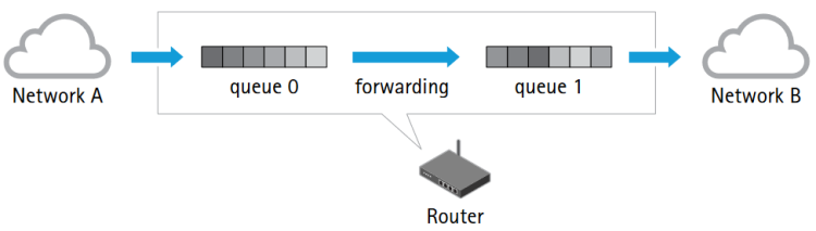
Queue disciplines
To be able to provide the mechanism desired by DiffServ the routers implement different ways of handling its queues. These different techniques are known as queuing disciplines and are algorithms designed to provide different service guarantees.To exemplify the use of different queuing disciplines we will briefly explain FIFO queues and priority queues.
FIFO is the simplest queuing discipline and is usually the default setting in network routers. FIFO describes the simple First-In-First-Out behavior of the queue. The below image shows a FIFO queue where packets enter from the left and exit to the right. The first packet entering will be the first packet sent out on the port. Other packets will be placed at the end of the queue and must wait their turn. This discipline is too basic to provide any QoS service.
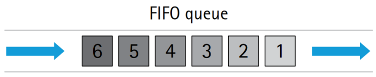
Priority queuing
Priority queuing is a relatively simple way of implementing differentiated service classes in a router. Instead of using one FIFO queue only, several are used, and each is assigned a different priority. A classifier determines which queue to put the incoming packet in, and the scheduler puts the packets out onto the network. The classifier parses the header of incoming packets and decides which priority queue to put the packetin. In a DiffServ network this decision is based on the DSCP value of the incoming packet. The scheduler ensures that the high priority queue gets served first, the medium priority queue next, and so on. This discipline allows the traffic to be prioritized.
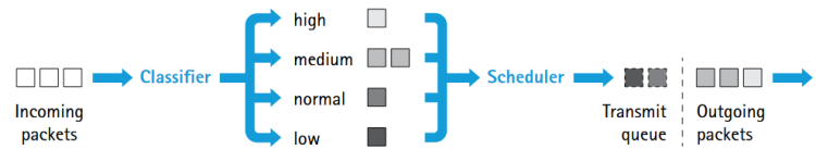
AXIS OS
Axis has opted to use the DiffServ model, to provide greater scalability and flexibility. This is implemented by:
Marking network traffic
Classifying network applications in QoS classes
Providing a user interface
AXIS OS QoS classes
AXIS OS uses four QoS classes. The members of a class all mark their traffic with the same DSCP value and thus receive the same forwarding treatment from routers:
Live video - This class consists of applications that stream Motion JPEG video streams over HTTP, and MPEG-4 video streams over RTP, RTP/RTSP and RTP/RTSP/HTTP.
Live audio - This class consists of applications that generate audio flows, and is only present in products that supportaudio.
Event/Alarm - This class consists of applications that generate event and alarm traffic. The class handles FTP, HTTP, SMTP and TCP events.
Management - This class consists of applications that generate management traffic. The class can handle FTP, HTTP, HTTPS and SNMP management traffic.
AXIS OS QoS configuration
The image below shows an example of a screenshot of the HTTP user interface for QoS in Axis devices using AXIS OS 6.5X and lower. It shows the different QoS classes supported by the product and lets the user specify the DSCP (DiffServ Codepoint) value for each class. The default DSCP value is 0, which is the same as the default PHB and which can be interpreted as QoS disabled.
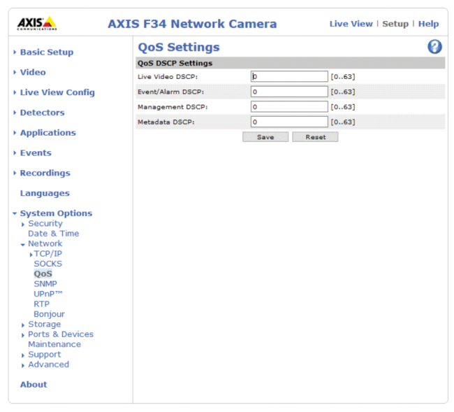
In Axis devices running AXIS OS 7.10 and higher the Plain Config in Settings > System > Plain Config > Network is used to perform QoS related configuration.
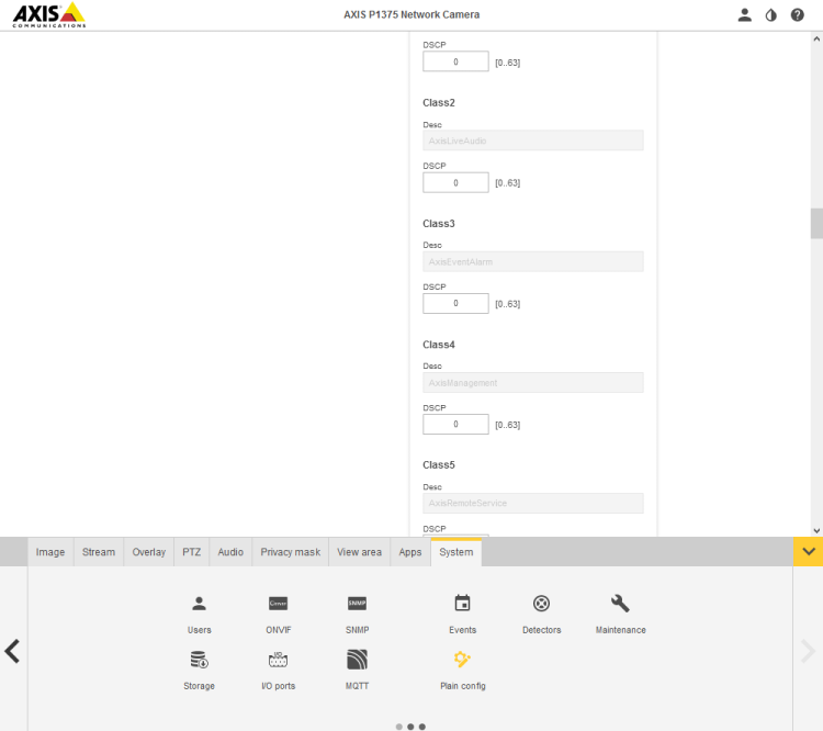
Performance improvements
The graph below illustrates a possible scenario in which performance is maintained/improved on a QoS enabled network.
Video is first streamed over a quiet, non-QoS network, where the frame rate can be assumed to be approximately 30 frames per second. This is illustrated by line A.
Network congestion is then simulated by, e.g., adding a non-responsive UDP stream. The frame rate drops sharply, to a practically unusable level, as shown by line B.
Video is then streamed over a DiffServ-enabled network, with the same congestion also added here. The video traffic is unaffected by the congestion and the frame rate is maintained, as shown by line C.
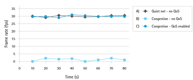
TCP ECN
ECN is an acronym for Explicit Congestion Notification and is an improvement of the congestion control i n T C P. The basic idea is for TCP to report that congestion is about to occur, before the queue actually overflows. The router does this by marking a field in the IP header called CE (Congestion Experienced). When the sender receives this signal the flow is slowed down. The traditional method of indicating congestion is for routers to drop packets that lead to the re-transmission of packets.
The ECN model will only be used when both communication end-points support it. This is achieved by negotiating at TCP connection initialization time. By introducing ECN support re-transmission over the network is minimized, which leads to higher throughput and less delay. TCP ECN is enabled by default in Axis video products and can be disabled in Plain Config > Network > TCP ECN.
IPv6
IPv6 (Internet Protocol version 6) was initially designed by the IETF to replace the current IP version 4 (IPv4). The most likely scenario now is that IPv4 will remain even after IPv6 enters the arena. One of the main reasons for the introduction of IPv6 is the growing shortage of IPv4 addresses. Additionally, IPv6 also adds improvements in areas such as routing and network auto-configuration. Some general information about IPv6 addresses and configuration is provided in the following sections, and the complete IPv6 specifications can be found in the RFC 2460 specifications.
IPv6 addresses
The IPv6 address is written in hexadecimal form, and consists of eight double-bytes separated by colons. To make the address representation as short as possible, a number of consecutive zeros may be abbreviated to a double colon, which is allowed once in any single IPv6 address. Instead of using a subnet mask as in IPv4, IPv6 simply uses a network prefix length. The prefix length is appended to the address.
Example: fe80::250:daff:fe4d:7592/64
The prefix length specifies how many bits of the address will be considered part of the prefix. In the example above, the first 64 bits specify the network address, while the final 64 bits specify the host address. IPv6 addresses can be assigned in different ways:
A link-local IPv6 address is automatically configured.
A DHCPv6 server can be used to assign IPv6 addresses.
Router advertisements can be used to assign auto-configured addresses.
Auto-configured link-local address
A device that supports IPv6 will get an auto-configured link-local address that starts with fe80. The remainder of the address is usually built on a so-called EUI64 address. The EUI64 address is constructed by taking the Ethernet MAC address of the network interface, and filling it with two specific bytes (fffe) in the middle, to get a 64-bit address (see the example address in the previous section.)
Auto-configuration using router advertisements
In an IPv6 network, network devices may be auto-configured by listening to advertisements sent by routers in the network. These advertisements will then define how the network devices should be configured in order to be able to be routable. A routable IPv6 address can be derived by using the information in the router advertisements. This auto-configured address is derived using the EUI64 address, together with the address of the router and the network prefix. The router advertisements may instruct the network device to use DHCPv6, and if so, at which level.
DHCPv6 configuration
Just as an IPv4 network may use a DHCP server to assign IP configuration, an IPv6 network may use a DHCPv6 server. DHCPv6 can be used at different levels:
In stateless mode the DHCPv6 server will designate the network servers to use, e.g., DNS servers and NTP servers, but it will not assign IPv6 addresses for network devices. This must be done using some other method.
In stateful mode, the DHCPv6 server will also assign IPv6 addresses to the network devices, as well as assigning the network servers as in stateless mode.
Accessing IPv6 devices
Most programs accept host names and will automatically look up the IPv6 address. This is the preferred way of passing addresses to programs. If the name maps to an IPv4 address, IPv4 will be used. If the name maps to an IPv6 address, IPv6 will be used. If there are both IPv4 and IPv6 mappings, the operating system will decide which to try first. To pass IPv6 literal addresses to a program, there are a few points to consider. When passing an URL, brackets must be used. To pass IPv6 literal addresses to a program, there are a few points to consider. When passing an URL, brackets must be used. For example:
| Example | Comment |
| http://[2001:5c0:84d9:2:240:8cff:fe6b:3cb9] | Accessing an Axis device using http |
| http://[2001:5c0:84d9:2:240:8cff:fe6b:3cb9]:8080 | Accessing an Axis device using http and custom httpport |
| https://[2001:5c0:84d9:2:240:8cff:fe6b:3cb9] | Accessing an Axis device using https |
| http://root:pass@[2001:5c0:84d9:2:240:8cff:fe6b:3cb9] | Accessing an Axis device using http and pre-entered access credentials |
| http://[fe80::2:240:8cff:fe6b:3cb9%eth0] | Accessing an Axis device using the link-local address. Note that the network interface is specified after the IPv6 address. This is because the link-local prefix fe80::/10 has multi-path routes, i.e., one route per interface. The routing system has no way of knowing which interface the device you are trying to contact is located on. |
Most programs (e.g., FTP, Telnet, etc) will accept the IPv6 address in its literal form such as ftp 2001:5c0:84d9:2:240:8cff:fe6b:3cb9 or ftp fe80::2:240:8cff:fe6b:3cb9%4. Some programs may take the interface identifier in a non-standard way. An example of this is the ping6 tool usually distributed with linux. It expects to be run like this ping6 -I eth1 fe80::2:240:8cff:fe6b:3cb9. On Windows you can see the identifier of each adapter by running ‘ipconfig’ and finding the IPv6 link-local address of that interface. It may look something like this:
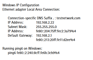
Common IPv6 addresses and ranges
| IPv6 address | Explanation |
| 0:0:0:0:0:0:0:0 | Equals IPv4 0.0.0.0 and is the source address of a host before it receives an IP address from DHCP |
| 0:0:0:0:0:0:0:1 | Equals ::1 and is the equivalent of IPv4 127.0.0.1 |
| 0:0:0:0:0:0:192.168.100.1 | This is how an IPv4 address would be written in a dual-stack mixed IPv4-IPv6 environment |
| 2000:::/3 | The global unicast address range |
| FC00::/7 | The unique local unicast range |
| FE80::/10 | The link-local unicast range |
| FF00::/8 | The multicast range |
| 3FFF:FFFF::/32 | Reserved for examples and documentation |
| 2001:0DB8::/32 | Reserved for examples and documentation |
| 2002::/16 | Used for IPv6 to IPv4 tunneling and used as a transition system which allows IPv6 packets to be transported over an IPv4 network without the need to configure an explicit tunnel. |
IPv6: AXIS OS configuration
Web interface
The IP configuration of the Axis video product is usually made from the TCP/IP settings (see section 2.1) pages in the embedded web interface. In addition to this, you can list the parameters directly in the Plain Config page. From here you can customize the IPv6 configuration, by changing parameters that are not available from the TCP/IP settings page. On the TCP/IP settings page, it is possible to enable or disable the use of IPv4 and/or IPv6.
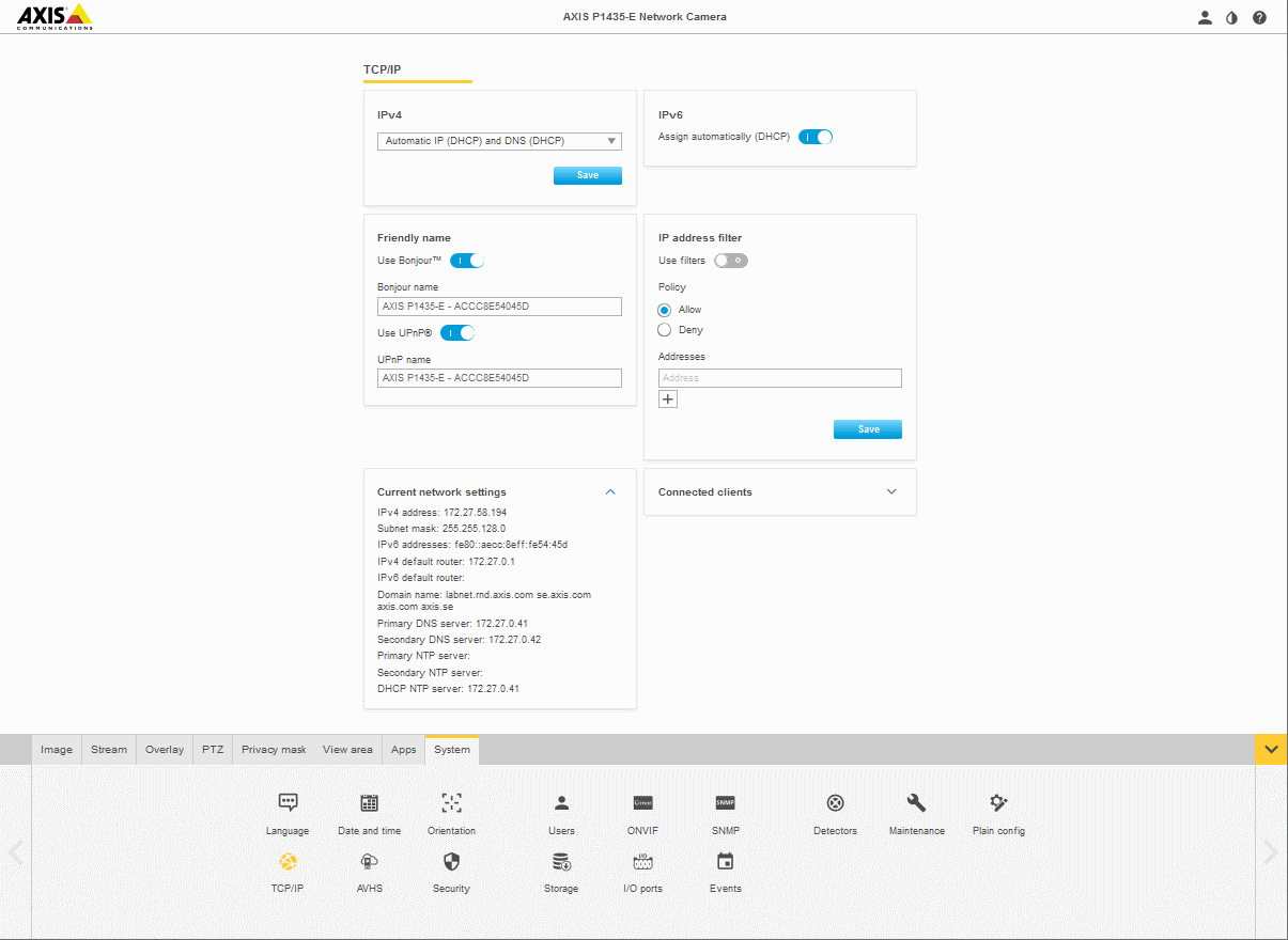
The user is prohibited from disabling both IPv4 and IPv6, since this will render the Axis device inaccessible. It is however, still possible to disable both IPv4 and IPv6 from the Plain Config page. If this happens, the Axis device will override the configuration and start IPv4 according to the IPv4 configuration.
Use of IPv4 is enabled by default. When IPv4 is disabled no IPv4 configuration will be made on the device. The device will then only be accessible via IPv6. Note that when IPv4 is disabled, a link-local IPv4 address will not be assigned, even if the use of a link-local IPv4 address is enabled on the Advanced TCP/IP Settings page.
Use of IPv6 is disabled by default. When IPv6 is enabled, the Axis device will assign a link-local IPv6 address. By default, the device will also listen to router advertisements and assign IPv6 addresses accordingly. It is possible to change the IPv6 configuration behavior using the plain configuration interface found in the Advanced System Options menu. For further descriptions of the advanced IPv6 settings.
Plain Config
The IPv6 configuration is by default set to accept router advertisements and to use DHCPv6 according to the router advertisements. In different environments it may be necessary to change the IPv6 configuration. To do this, go to the Plain Config page and select the Network parameter group. By altering the parameters in the Network.IPv6 parameter group, the behavior of the IPv6 configuration is changed. The group consists of five parameters:
| Parameter | Comment |
| Network.IPv6.Enabled | This parameter is used to enable or disable IPv6 network configuration. |
| Network.IPv6.AcceptRA | The Accept router advertisements parameter is used to enable or disable the said functionality. If this parameter is set to yes, the Axis device will listen to router advertisements on the network and perform IPv6 configuration according to it. |
| Network.IPv6.DHCPv6 | This parameter is used to configure either of the four DHCPv6 client settings
|
| Network.IPv6.IPAddress | The IP Address parameter is used to manually set an IPv6 address. This address will be used in parallel with other IPv6 addresses that may be set by DHCPv6 or by router advertisements. If a specific prefix length is requested the prefix length is defined last in the address, like this: 2001:5c0:84d9:2::1:3b/128. If no prefix length is defined, the default length 64 will be used. |
| Network.IPv6.DefaultRouter | The Default router parameter is used to manually set an IPv6 default router. This address will be set in parallel with other IPv6 addresses that may be set by DHCPv6 or by router advertisements. |
| Additional Information | The IPv6 addresses currently in use are read from the IP address parameter In the Network.<interface>.IPv6 group, where <interface> is the name of the interface (e.g. eth0, eth1 etc..). This parameter lists all IPv6 addresses, separated by space characters. |
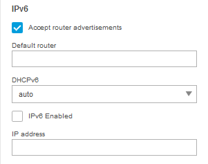
IEEE 802.1X
There are different levels of security for a network’s infrastructure and the devices connected to it. The first level is authentication and authorization. The user or device identifies itself to the network and the remote end by a username and password, which are then verified before the device is allowed into the system. Added security can be achieved by encrypting the data to prevent others from using or reading the data. Common methods are HTTPS (also known as SSL/ TLS), VPN, and WEP or WPA in wireless networks. IEEE 802.1X is an authentication and authorization technique. Axis network video products support IEEE 802.1X as a security feature. This section presents the background of IEEE 802.1X, as well as its working principle. It also describes how IEEE 802.1X should be used in Axis devices, and how the RADIUS (remote authentication dial-in user service) servers and switches need to be configured. The intended audience of this document is technical personnel and system integrators.
IEEE 802.1X is an IEEE standard for port-based network access control (“port” means the physical connection to the LAN infrastructure). It is part of the IEEE 802.1 group of networking protocols and provides an authentication mechanism for devices to connect to a LAN, either establishing a connection or preventing the connection if authentication fails. IEEE 802.1X prevents what is called “port hi-jacking”, that is, when an unauthorized computer gets access to a network through a network jack inside or outside a building. IEEE 802.1X is useful in network video applications since their devices are often located in public spaces where a network jack can pose a security risk. In modern enterprise networks, IEEE 802.1X is becoming a basic requirement for anything that is connected to a network.
Working principle
There are three basic terms in IEEE 802.1X. The user or client that wants to be authenticated is called a supplicant. The actual server doing the authentication, typically a RADIUS server, is called the authentication server. And the device in between, such as a switch, is called the authenticator. The protocol used in IEEE 802.1X is EAPOL (Extensible authentication protocol encapsulation over LANs). There are several modes of operation, but the most common case is described here:
The authenticator sends an “EAP-Request/Identity” packet to the supplicant as soon as it detects that the network link is active (this could be because the supplicant, for example a specific Axis device in a network video system, is connected to the switch).
The supplicant sends an “EAP-Response/Identity” packet to the authenticator.
The “EAP-Response/Identity” packet is then passed on to the authentication (RADIUS) server by the authenticator.
The authentication server sends back a challenge to the authenticator, such as with a token password system.
The authenticator unpacks this from IP and repackages it into EAPOL and sends it to the supplicant. Different authentication methods will vary this message and the total number of messages. EAP supports client-only authentication and strong mutual authentication.
The supplicant responds to the challenge by the authenticator.
The authenticator passes the response to the challenge onto the authentication server.
If the supplicant provides proper identity, the authentication server responds with a success message to the authenticator.
- The success message is then passed onto the supplicant by the authenticator. The authenticator now allows access of the supplicant to the LAN, possibly restricted based on attributes that came back from the authentication server. For example, the authenticator might switch the supplicant to a particular virtual LAN or install a set of firewall rules.
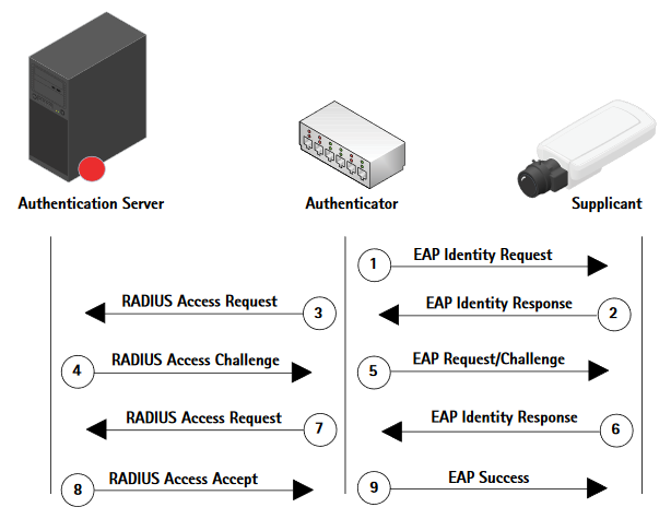
It should be noted that setting up and configuring IEEE 802.1X is a fairly complex procedure, and it is important that RADIUS servers, switches, and clients (such as Axis devices) are set up correctly.
IEEE 802.1X: AXIS OS configuration
Web interface
To gain access to a protected network, the Axis device must have a CA certificate, a client certificate, and a client private key. These should be created by the servers and uploaded via a web interface. When the Axis device is connected to the network switch, the device will present its certificate to the switch. If the certificate is approved, the switch allows the device access on a preconfigured port. As pointed out previously, in order to use port-based authentication, the network must be equipped with a RADIUS server and a network switch with support for IEEE 802.1X. You may also need to contact your network administrator for information on certificates, user IDs and passwords depending on the type of RADIUS server that is used.
The settings here enable the Axis device to access a network protected by IEEE 802.1X/EAPOL (Extensible Authentication Protocol over LAN). There are many EAP methods available to gain access to a network. Before AXIS OS 11.6, the protocol used by Axis is EAP-TLS (EAP-Transport Layer Security) for wired and wireless IEEE 802.1X network authentication, as well as EAP-PEAP/MSCHAPv2 for wireless IEEE 802.1 network authentication.
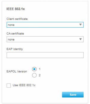
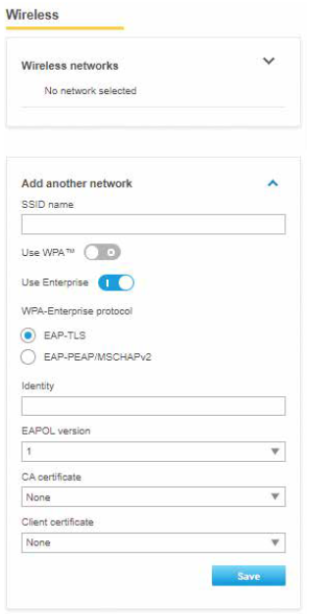
The client and the RADIUS server authenticate each other using digital certificates provided by a PKI (public key infrastructure) signed by a certification authority. Note that to ensure successful certificate validation, time synchronization should be performed on all clients and servers prior to configuration. Further configuration of Axis devices should be performed on a safe network to avoid MITM (man in the middle) attacks. Terms used in the web interface are described as follows:
CA certificate - The CA certificate is created by the certification authority for the purpose of validating itself and the Axis device needs it to check the server’s identity. Select the correct certificate that was uploaded previously in the security tab under CA certificates. From AXIS OS 10.1 and onwards, selecting no CA certificate (none) means the Axis device will skip doing any validation of the server's identity.
Client certificate - The Axis device must also authenticate itself using a client certificate. Select the correct certificate that was uploaded previously in the security tab under client certificates.
EAPOL version - Select the EAPOL version (1 or 2) used in your network switch.
EAP identity - Enter the user identity associated with your certificate. A maximum of 16 characters can be used.
With AXIS OS 11.6 and later, we added support for EAP-PEAP/MSCHAv2 for wired connection. With AXIS OS 11.8 and later, customers can configure EAP-PEAP/MSCHAPv2 through the web interface.
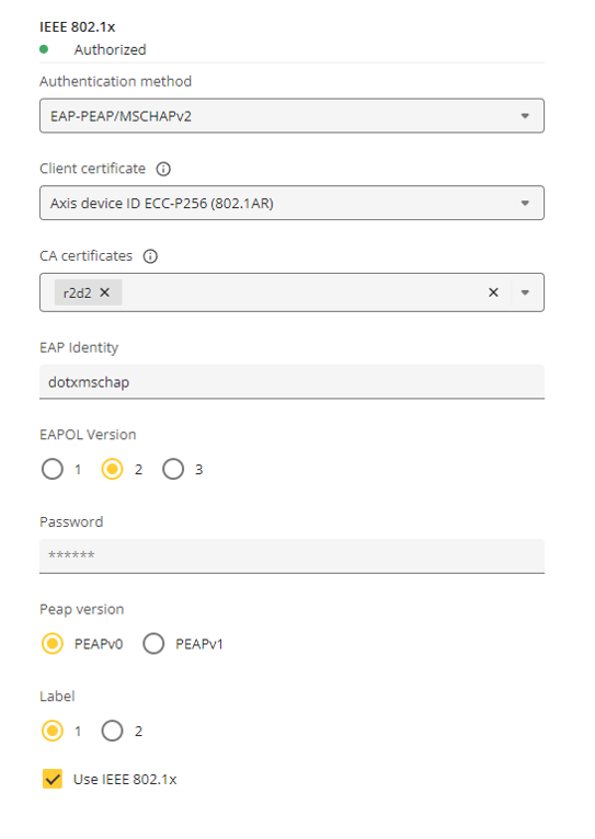
Client certificate - This is not needed for this authentication mode.
CA certificate - Optional. The CA certificate is created by the certification authority for the purpose of validating the server’s identity by the Axis devices. No CA certificate (none) means the Axis device will skip doing any validation of the server's identity.
EAP identity - The username for MSCHAPv2 authentication.
EAPOL version - Select version 2.
Password - The password for MSCHAPv2 authentication.
Peap version - Select PEAPv0.
Label - Select 1.
IEEE 802.1AE
With AXIS OS 11.8 and later, IEEE 802.1AE MACsec capabilities were added to AXIS OS-based devices.
IEEE 802.1AE MACsec (Media Access Control Security) is a well-defined network protocol that cryptographically secures point-to-point ethernet links on network layer 2 ensuring the confidentiality and integrity of data transmissions between two hosts.
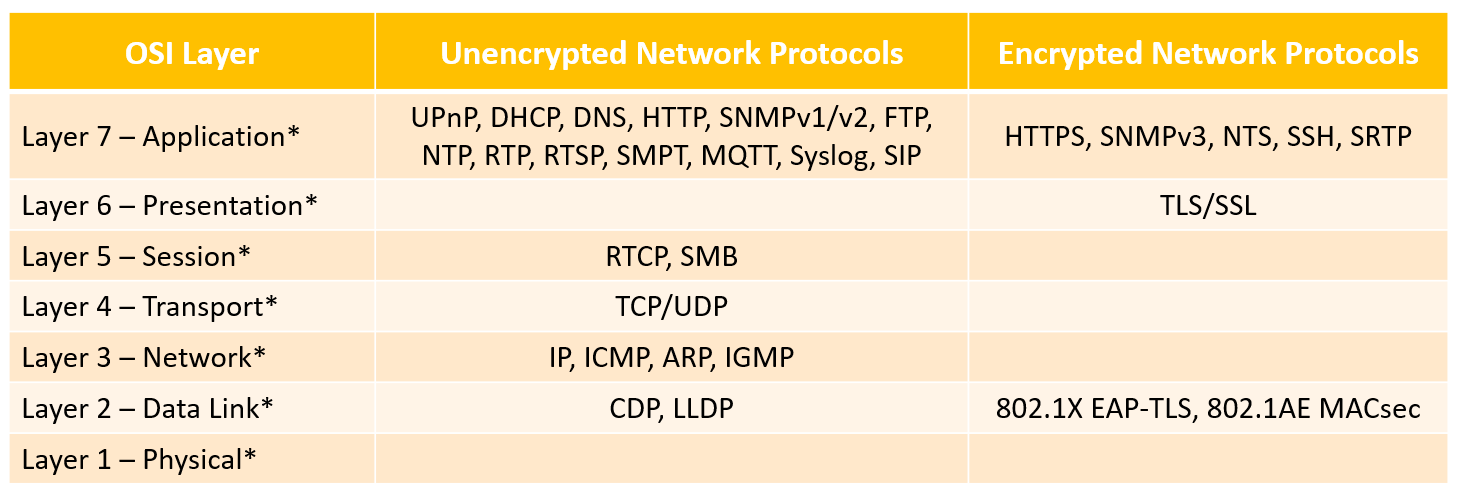
* List of example network protocols used by Axis devices that are protected by IEEE 802.1AE MACsec. MACsec adds protection to network protocols without native security capabilities and adds an additional layer of protection as well to network protocols with built-in security.
Unlike protocols such as IPSec which operates at Layer 3 as an end-to-end technology, MACsec encrypts each frame that leaves the Ethernet LAN and decrypts the frames as it enters the Ethernet LAN. In order to achieve end-to-end network encryption using MACsec, all links/hops in between source and destination need to have MACsec enabled to ensure traffic traversing across a network is MACsec protected.
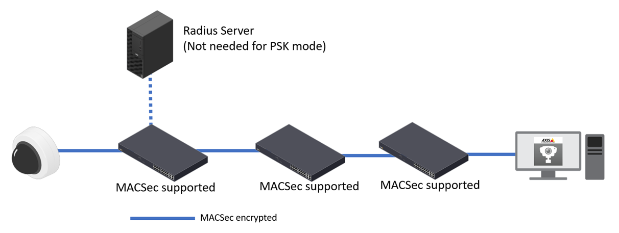
A single link/hop that does not support MACsec will therefore leave network traffic unencrypted from that link/hop to the next.
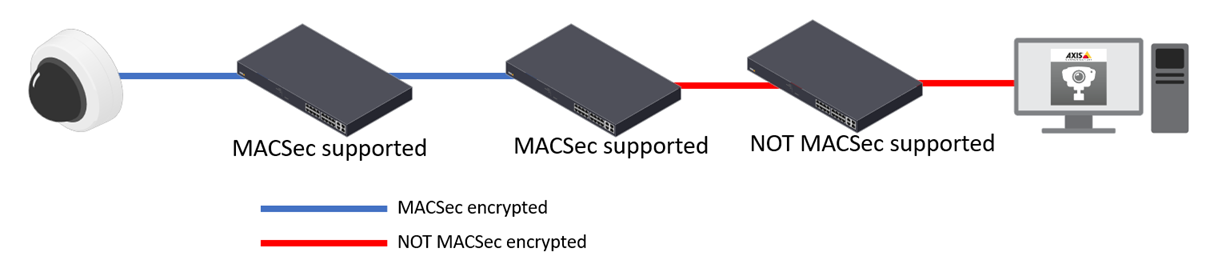
Not only does MACsec prevent unauthorized access to network data streams through strong encryption but also prevents man-in-the-middle attack scenarios. Because MACsec operates at the low layer 2 of the network stack, it adds an additional layer of security to network protocols that do not offer native encryption capabilities (ARP, NTP, DHCP, LLDP, CDP…) as well as ones that do offer it alike (HTTPS, TLS). The illustration below outlines the MACsec frame.
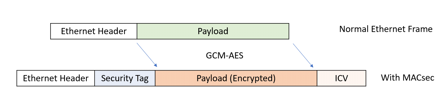
A Security Tag (SecTAG) containing MACsec parameters is inserted immediately after the source mac address in the Ethernet Header. The Integrity Check Value(ICV) is calculated via an agreed algorithm by the sender and attached to the frame. When the receiver receives the frame, it will use the same algorithm to calculate the ICV again and compare it with the one attached to the packet. The integrity is confirmed if the two ICV values are identical which means the packet is not tampered.
Terminologies
| Acronym | Terminology | Description | |||
| CA | secure Connectivity Association | A security relationship, established and maintained by key agreement protocols, that comprises a fully connected subset of the service access points in stations attached to a single Local Area Network (LAN) that are to be supported by MACsec | |||
| CAK | Connectivity Association Key | This key is used to derive the actual keys for the data encryption. CAK can be either manually specified or derived via 802.1x authentication. | |||
| CKN | Connectivity Association Key Name | The name of the CAK. | |||
| MKA | MACsec Key Agreement | The protocol used to negotiate the keys for MACsec. | |||
| SC | Secure Chanel | A security relationship used to provide security guarantees for frames transmittedfrom one member of a Connectivity Association (CA) to the others. | |||
| SAK | Secure Association Key | It is derived from a CAK using a specific algorithm and encrypts data transmitted through an SC. | |||
The MACsec Key Agreement (MKA)
When implementing MACsec between two devices, the MACsec Key Agreement(MKA) protocol provides and manages the session keys. The MKA protocol relies on the EAP framework to establish the communication. The two devices establish a unique connectivity association. Within the CA, there are two secure channels, one for inbound traffic, and the other one for outbound traffic. The two devices use the same cipher suite for data encryption.
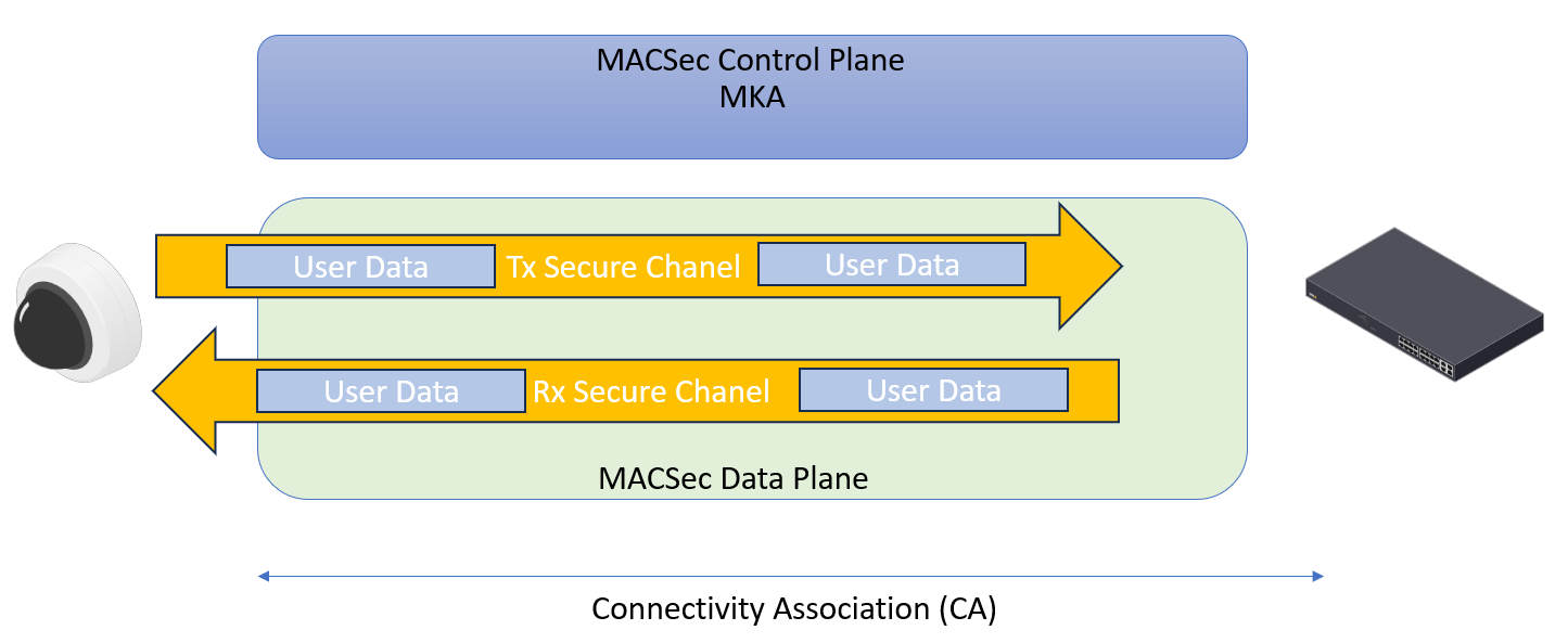
MACsec Ciphers
To protect the confidentiality of the data traveling through the MACsec Secure Channel, the packets are encrypted by the industrial standard GCM-AES-128 or GCM-AES-256 cipher suites. There are another two cipher suites GCM-AES-XPN-128 and GCM-AES-XPN-256. XPN standards for Extended Packet Numbering, these two ciphers are generally used on high-speed links.
In the current implementation, AXIS OS supports GCM-AES-128 cipher suite only. Additional cipher suites can be added on demand.
MACsec modes
The IEEE 802.1AE MACsec standard describes two modes of operation, a manually configurable Pre-Shared Key (PSK)/Static CAK mode and an automatic Master Session/Dynamic CAK mode using IEEE 802.1X EAP-TLS sessions. The Pre-Shared Key mode is recommended to be used when the connecting network switch is not capable of supporting auto-negotiation through IEEE 802.1X EAP TLS.
Since IEEE 802.1X EAP-TLS is enabled by default and through that, MACsec Master Session/Dynamic CAK mode is also automatically enabled. When plugging in a factory defaulted Axis device, IEEE 802.1X network authentication will be tried and when successful, MACsec Dynamic CAK mode will be tried as well. If the connected switch does not support IEEE 802.1X EAP TLS and/or MACsec Dynamic CAK, then the Axis device will simply connect anyway without further enforced security mechanisms.
Pre-shared Keys (PSK), Static CAK mode
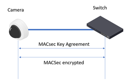
In pre-shared key(PSK) mode, also known as static CAK mode, the MACsec implementation is comprised of three phases: PSK configuration, MKA key negotiation and MACsec data encryption and decryption.
This mode requires the user to configure the to-be-used pre-shared key on both devices, the Axis device and the network switch. Every PSK consists of two fields: a connectivity association key name (CKN) and a connectivity association key (CAK). The CKN and CAK must match on both ends of the ethernet link.
Once the pre-shared key is verified, the MKA protocol is enabled to maintain the MACsec session on the link. One participant on the link will be elected as the key server and its primary responsibility is to generate, distribute and refresh the Secure Association Key(SAK). The SAK is the actual key used for encrypting the data. The MKA protocol limits the number of frames that can be protected with a single SAK. When the Packet Numbers (PNs) in an SA are exhausted, the corresponding SAK will be refreshed.
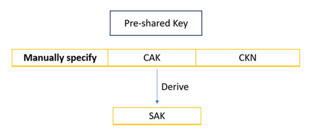
Axis device configuration
To configure the MACsec PSK in AXIS OS devices, go to System > Security > IEEE 802.1ae MACsec > Mode, select “Static CAK / Pre-Shared Key(PSK)” mode.
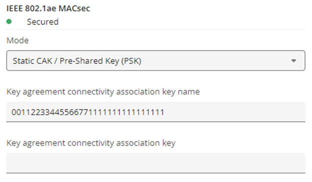
The CAK must be either 16 bytes (32 hexadecimal characters) or 32 bytes (64 hexadecimal characters). The CKN must be 1 to 32 bytes (2 to 64 and divisible by 2) hexadecimal characters.
At the time of writing this article, please also check the box to enable IEEE 802.1x before saving the configuration. When MACsec is secured, the status of IEEE 802.1x will show “authorized”. We are in the process of optimize this as MACsec PSK mode doesn’t work in conjunction with 802.1x.
Switch configuration
The below configuration example is outlined using the Aruba CX switch series.
1. Configure the MACsec policy
switch(config)# macsec policy axis_ms_policy
switch(config-macsec-policy)# cipher-suite gcm-aes-128
switch(config-macsec-policy)# replay-protection window-size 100
switch(config-macsec-policy)# exit
switch(config)#
2. Configure the MKA policy
switch(config)# mka policy axis_mka_policy
switch(config-mka-policy)# pre-shared-key ckn 00112233445566771111111111111111 cak plaintext 00112233445566771111111111111111
switch(config-mka-policy)# key-server-priority 5
switch(config-mka-policy)# exit
switch(config)#
3. Apply the MAC on the switch port
switch(config)# interface 1/1/28
switch(config-if)# apply macsec policy axis_ms_policy
switch(config-if)# apply mka policy axis_ms_policy
switch(config-if)# exit
switch(config)#
Master Session Key (802.1x,EAP-TLS), Dynamic CAK mode
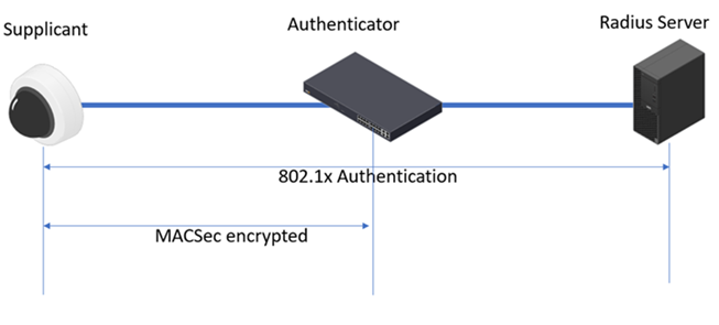
When implementing MACsec in conjunction with EAP-TLS, the Authenticator or the access switch performs the 802.1x authentication against the devices first. Once authentication is successful, the Radius server sends the master session key (MSK) to the switch and the device. The CAK and CKN will be derived from the MSK by both parties.
Following that, the MKA protocol is enabled on both parties on the link to start the MACsec session. Same as the PSK mode, one of the parties will be elected as the key server to manage the SAK keys. Once the SAK key is exchanged between the parties, the MACsec encryption and decryption starts.
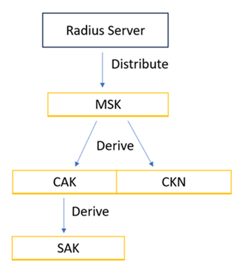
Axis device configuration
Since AXIS OS 10.1 (September 2020), IEEE 802.1X is enabled in the factory default state using the IEEE 802.1AR-compliant Axis device ID certificate. The Axis device will automatically try to authenticate against an IEEE 802.1X-enabled network. For manual IEEE 802.1X configuration, please refer to the AXIS OS Knowledge base. To use 802.1x port-based authentication, the network must be equipped with a RADIUS server and a network switch with support for IEEE 802.1X and IEEE 802.1AE MACsec. You may also need to contact your network administrator for information on certificates and further configuration of the RADIUS server.
Once the 802.1x authentication is done, if the switch supports MACsec, the MACsec talk will happen accordingly.
Freeradius Server configuration
Once the Freeradius server is up and running, there is just one additional step needed to enable the usage of MACsec through the Freeradius server side. The FreeRADIUS server in this case needs to send the EAP-KEY-NAME attribute for the switch to derive the Session-ID used in creating the CKN and CAK for MKA.
To enable FreeRADIUS to send the EAP-Session-ID in Access-Accept frames, please uncomment the following lines inside:
/etc/freeradius/sites-enabled/default for FreeRADIUS 2.xor
/etc/freeradius/3.0/sites-enabled/default in case of FreeRADIUS 3.x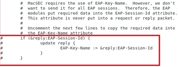
In this document, we are using the Aruba CX switch series that requires a User-Role after the 802.1x authentication to trigger the MACsec. The “Aruba-User-Role” is a vendor-specific-value sent from the FreeRadius server to the Aruba switch based on the EAP-identity configured in the AXIS OS devices. To do that, please add below to the file /etc/freeradius/3.0/users.
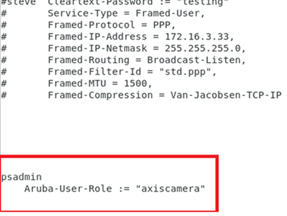
Aruba ClearPass Policy Manager configuration
Please follow the instructions here to securely onboard the Axis devices into Aruba networks. The integration guide outlines example configurations in great detail using IEEE 802.1AR and 802.AE MACsec for secure zero trust network integration of Axis devices into Aruba networks. The “Aruba-user-Role” attribute must also be dispatched from the ClearPass Policy Manager to the switch.
Aruba switch configuration
1. Configure the MACsec policy
switch(config)# macsec policy macsec-eap
switch(config-macsec-policy)# cipher-suite gcm-aes-128
switch(config-macsec-policy)# replay-protection window-size 100
switch(config-macsec-policy)# exit
switch(config)#
2. Configure the port-access role
switch(config)# port-access role axiscamera
switch(config-pa-role)# associate macsec-policy macsec-eap
switch(config-pa-role)# auth-mode client-mode
3. enable MACsec on the port
switch(config-if)# aaa authentication port-access dot1x authenticator
switch(config-if-dot1x-auth)# macsec
switch(config-if-dot1x-auth)# mka cak-length 16
The cak-length should be configured to 16 bytes for the dot1x authentication mode in our current implementation.
Verify the MACsec status on the AXIS OS devices:
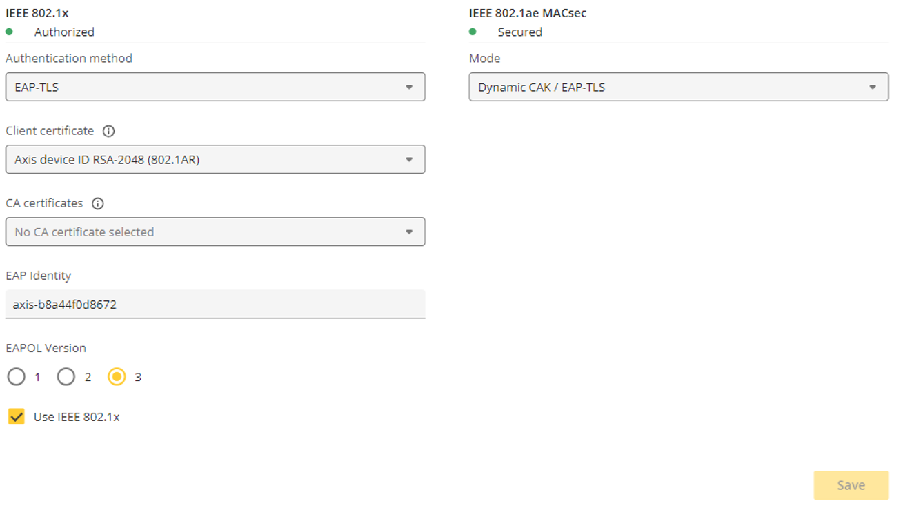
Below is what the MACsec frames look like when doing a packet trace from the camera directly. Go to System > Logs > Network trace.
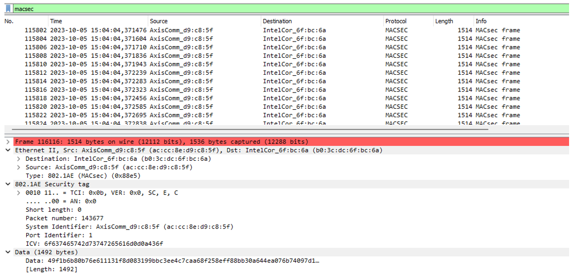
Verify the MACsec status on the Aruba Switch:
switch# show macsec status
MACsec Protocol Status
 Interface  Port ID  Policy                    Protection           Status  State
 ---------- -------- ------------------------- -------------------- ------- --------------
 1/1/27     1        macsec-eap                IC, Conf, Offset 0   Up      Retire
 1/1/28     1        axis_ms_policy            IC, Conf, Offset 0   Up      Retire
SW23# show mka policy
MKA Policy Details
===================
Policy Name: MKA_Auth_1/1/27_b8a44f4645f4
---------------------------------------------------------------------------
Mode : EAP-TLS
CKN : b0d80475242fbcd5c97ece50670e4dfe
CAK (encrypted) : AQBapQh5tkM/wWCQLE4jp0G/Iu6IfO+QutBMu8gFBKf...
Key-server Priority : 0
Transmit Interval : 2 seconds Policy Name: axis-mka_policy
---------------------------------------------------------------------------
Mode : Pre-shared key
CKN : 00112233445566771111111111111111
CAK (encrypted) : AQBapcO5rGnurI1zhrDB3JVwhbLmJhcgQkiRWgiJtfK...
Key-server Priority : 5
Transmit Interval : 2 secondsAxis device-to-device secure networking
- The feature is configured as "Not required" in the factory default state and during a standard AXIS OS upgrade to versions 12.6.85, 12.6.90 and 12.6.104.
- The feature is configured as "Disabled" in the factory default state with AXIS OS AXIS OS 12.6.108 and later versions.
- When upgrading from any version earlier than 12.6 to 12.6.108 and later, the feature remains "Disabled". However, when upgrading from 12.6, the existing configurations are preserved.
- We recommend that you connect only one device directly to the S3008 and S3008 MK II PoE port if you want to utilize the 802.1x authentication or MACsec security feature.
Securing interconnected Axis devices is essential to ensure safe onboarding and interconnection on the physical network. The best way to achieve this is by using the Axis device ID through IEEE 802.1X port-based authentication and IEEE 802.1AE MACsec.
As of AXIS OS 12.6, we introduced zero-touch secure networking for the S3008 and S3008 MK II recorders, featuring 802.1x authentication and MACsec support.
When you connect an Axis device with an Axis device ID and MACsec enabled, the S3008 performs 802.1x EAP-TLS authentication by verifying the device ID certificate. After successful authentication, MACsec negotiates to protect the layer 2 network traffic.
The following table shows three devices:
| Model | AXIS OS version | Axis device ID | MACsec | S30 port |
| M2026-LE Mk II | 9.80.95 | No | No | Port 1 |
| P3265-LVE | 10.12.289 | Yes | No | Port 2 |
| P3268-LVE | 12.5.73 | Yes | Yes | Port 3 |
When AXIS S3008 is running AXIS OS 12.6, the port security is set to “Not required” by default, allowing the S3008 to accept any connected devices. The following is a summary of the different security types:
Disabled: security check is off
Not required: 802.1x authentication is optional
Authentication required: 802.1x authentication is mandatory
MACsec secured required: both 802.1x and MACsec are mandatory
When you connect cameras to the devices, the port information changes as follows:
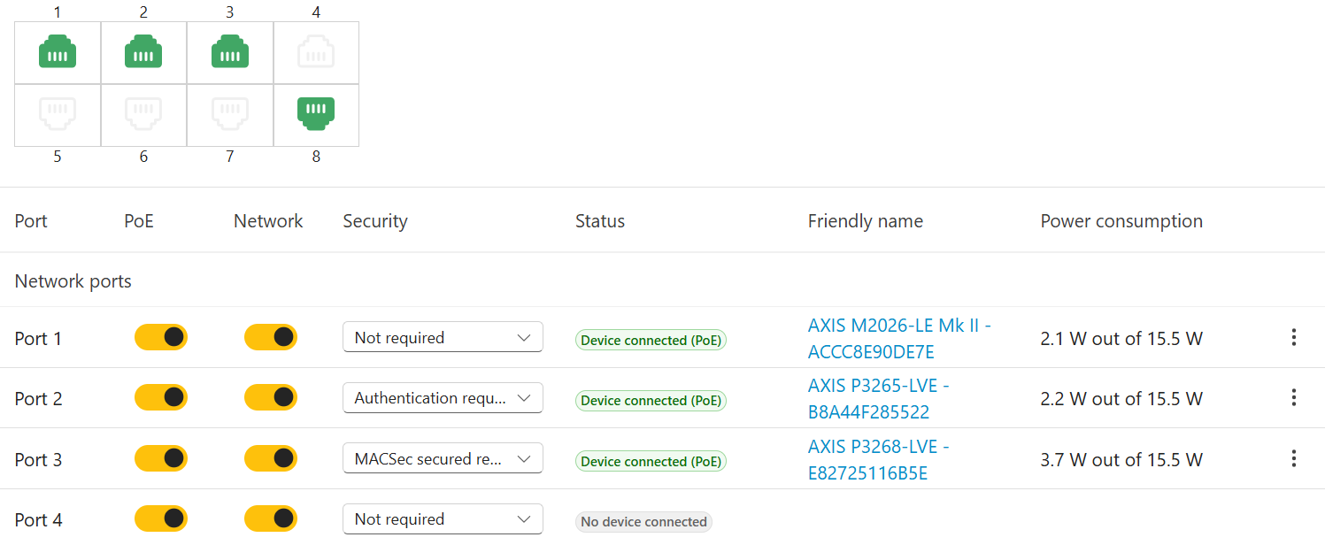
Port 1: Not required. As the device lacks an Axis device ID, the 802.1x authentication process fails.
Port 2: Authentication required. The P3265 has an Axis device ID, enabling successful 802.1x authentication. However, MACsec remains unsecured because the device is running AXIS OS LTS 10.12, which does not support MACsec.
Port 3: MACsec secured required. The P3268 has an Axis device ID, which enables successful 802.1x authentication. With MACsec enabled, a secure connection is also established.
When the port is set to Not required and you connect a device without a device ID to the S30 port, the S30 will attempt to authenticate the device up to three times. After that, 802.1x will be temporarily disabled, but the port will remain open, allowing the device to continue running.
The next time there’s a link state change on the port (for example, if the port goes down), the S30 will re-initiate the 802.1x authentication process. Devices with a valid device ID will then be authenticated and secured with MACsec (if enabled).
Once the security of a port is changed to either Authentication required or MACsec secured required, it automatically enforces 802.1x authorization or MACsec for subsequent connections. Any unauthorized attempts to access the port will be unsuccessful, as the S30 ports exclusively permit connections that are properly authenticated and MACsec-secured.
If you initially connect an 802.1x or MACsec-capable device to a port on the S30 and subsequently attempt to connect a non-MACsec or non-802.1x device, the connection will be blocked. In this case, you must manually adjust the security settings through the S30's web interface.
This feature is not available for S3016. MACsec PSK mode is not supported. The S3008 only supports authentication of the Axis device ID certificate. Customer-issued certificates from third-party certificate authorities are not supported.
WS-Discovery (Web Services Dynamic Discovery Protocol)
The Web Services Dynamic Discovery protocol utilizes UDP Port 3702 and defines itself as a multicast discovery protocol that is used to detect other devices and services on the network. ONVIF is relying on this protocol in order to detect other capable devices, so Axis devices support WS-Discovery for initial on-boarding and configuration. It’s recommended to disable the WS-Discovery after usage since it is vulnerable to attacks as described in this security advisory. See instructions below on how to disable WS-Discovery.
AXIS OS > 9.70
Disable the service by disabling the parameter Enable WS-Discovery discoverable mode in Settings > System > Plain config > WebService > DiscoveryMode > Enable WS-Discovery. For multiple device configuration in AXIS Device Manager, the corresponding VAPIX parameter is called DiscoveryMode.Discoverable.
AXIS OS 5.70 — 9.60
Enable SSH in Plain config > Network > SSH and connect to the Axis device via Putty
Type the following commands, each followed by pressing ENTER
systemctl mask wsddsystemctl mask wsdsystemctl mask wsd.socketsystemctl stop wsdd
Disable SSH again from Plain Config and restart the device
AXIS OS 5.60
Enable SSH in Plain Config > Network > SSH and connect to the Axis device via Putty
Type the following commands, each followed by pressing ENTER
rm /etc/rc3.d/S92wsdd/etc/init.d/wsdd stop
Disable SSH again from Plain Config and restart the device
AXIS OS < 5.50
Enable Telnet and connect to the Axis device via command-line tool. Go to Telnet access.
Type the following commands, each followed by pressing ENTER
rm /etc/rc3.d/S92wsdd/etc/init.d/wsdd stop
Disable Telnet again and restart the device
Bonjour
Bonjour is Apple’s implementation for zero-configuration networking. A method that helps the users to find services on a local network. By using mDNS and DNS-SD protocols, Bonjour covers three major areas:
Addressing
Bonjour self-assigns a link-local address if no DHCP server is present in the network. For IPv4, randomly selected from 169.254.0.0/16. For IPv6, the address is assigned from fe80::/10.Hostname to IP address translation
Bonjour uses multicast DNS (mDNS) in the local network to resolve a hostname.Service Discovery
Bonjour discovers the available services in the local network via DNS service records.
The mDNS protocol resolves the hostname to the IP address without relying on a conventional unicast-based DNS server in a local network. The mDNS messages are sent through multicast (IPv4: 224.0.0.251 or IPv6: ff02::fb) to UDP port 5353. The Axis device will select a domain name with the prefix “.local”, which only works with mDNS within the local network. An example domain name is “AXIS P1375.local”.
To discover a service and use that service in the network by a client, several DNS records are used in the process:
| Type | Name | Purpose | Convention |
| A | A Record | Resolve a hostname to an IPv4 address | |
| AAAA | AAAA Record | Resolve a hostname to an IPv6 address | |
| SRV | Service Record | Maps the service instance to the hostname and port number | <Instance Name>.<Service Type>.<Domain> |
| PTR | Pointer Record | Maps the service type to the specific instance of that service | <Service Type>.<Domain> |
| TXT | Text Record | The text field normally describes additional information about the service | Key=value |
Axis Bonjour implementation
Prior to AXIS OS 11.4, AXIS OS products used Bonjour to announce their presence in the network. Starting from AXIS OS 11.4, we added new service names — vapix-http and vapix-https — to simplify the discovery of Axis devices and better comply with the RFC 6763 specification. In the table below, you can see some examples of service names used on AXIS OS devices.
| Service name | Default instance name | Transport protocol | Port (default port number) | TXT | Remark | |
| < 11.4 | ≥ 11.4 | |||||
| axis-video | AXIS <model> - mac/serial number** | TCP | http port If http (and http re-direct) is disabled, it will not be advertised. | macaddress | Camera and audio products | |
| axis-bwsc | TCP | macaddress | Body Worn SCU | |||
| axis-nvr | TCP | macaddress | Recorders | |||
| http | AXIS <model> - mac/serial number** | AXIS <model>*** | TCP | 80 | ||
| https | TCP | 443 | ||||
| rtsp | TCP | 554 | path, camera | |||
| vapix-http* vapix-https* | N/A | TCP | The HTTP or HTTPS port of the service. By default 80 or 443. |
| Added from AXIS OS 11.4. | |
*VAPIX is Axis own open API (Application Programming Interface) to our products, using standard protocols that enable integration into a wide range of solutions on different platforms.
** Example: AXIS P1375 - B8A44F42B4C6
*** Example: AXIS P1375. If you add a second device of the same model, the second one will be named AXIS P1375 (2) and so on.
**** param stands for param.cgi, apidisc stands for apidiscovery, and decaf stands for device configuration framework. Decaf was added in AXIS OS 11.11 and is included in all subsequent versions.
***** This field is used by services to indicate temporary roles.
AXIS OS < 11.4
In the below example, an Axis P1375 camera is running on the AXIS OS version earlier than 11.4. We use AXIS IP Utility to discover an Axis device. AXIS IP Utility sends a query message including PTR record. Querying a service instance called “_axis-video._tcp.local”.
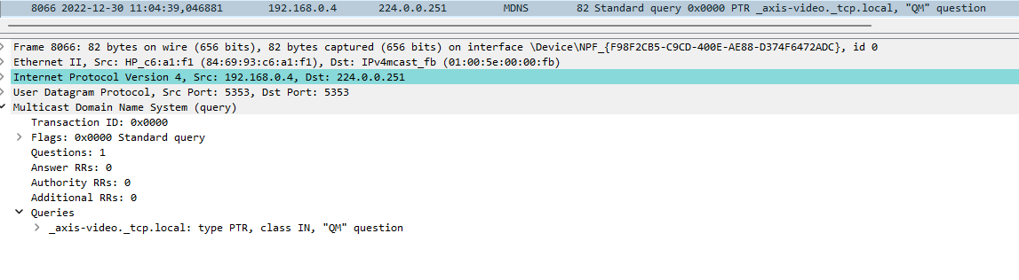
Once the Axis device receives the query message, it will respond with a mDNS query response containing the PTR record and additional records.
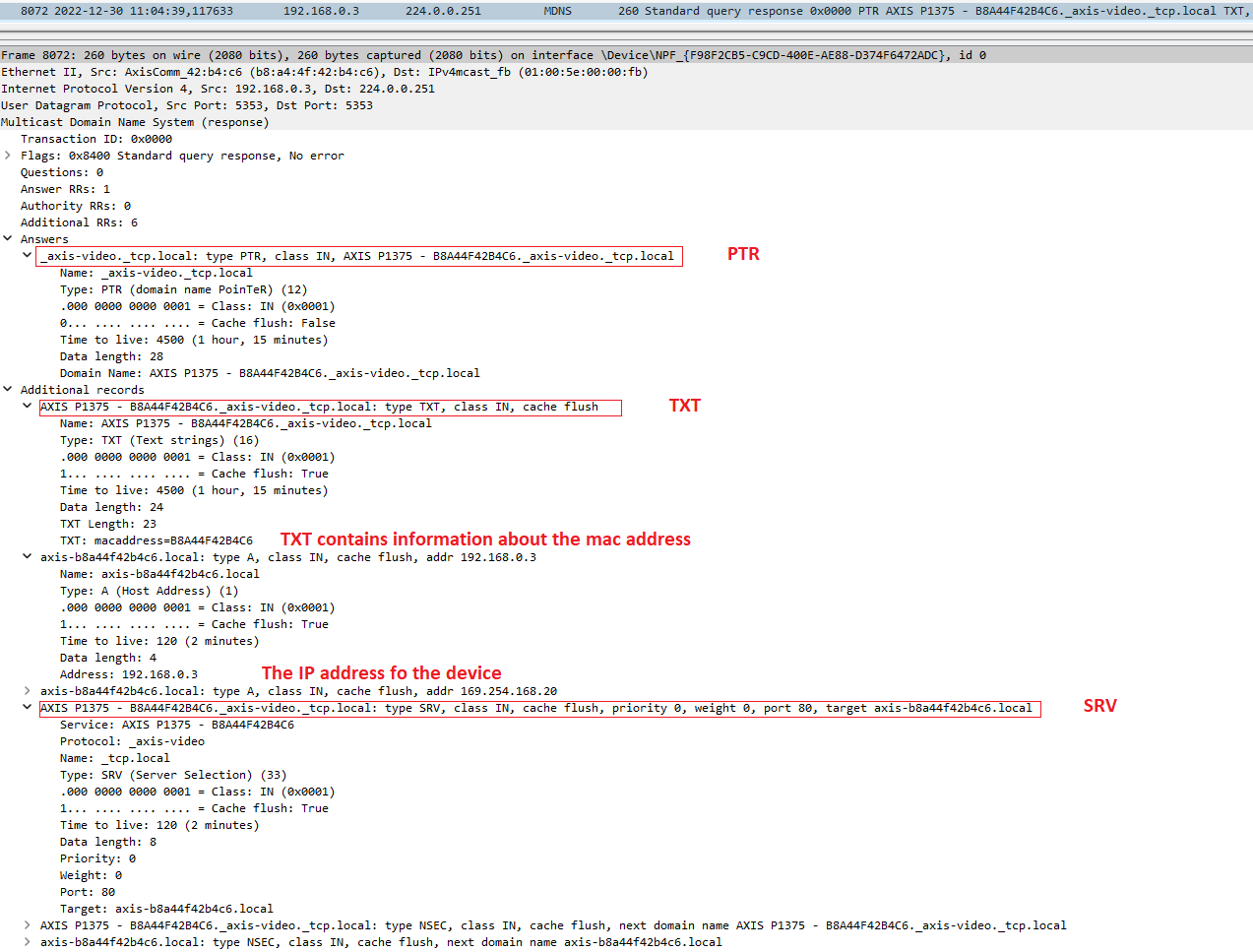
“AXIS P1375 - B8A44F42B4C6” is the service instance name. “_axis-video._tcp” is the service type that identifies what the service does and its transport protocol. In this example, the Axis device announces itself by providing the “_axis-video” service through TCP. The TXT record contains the mac address information of the Axis device.
AXIS OS ≥ 11.4
Below is another example that the same Axis P1375 camera running on version 11.4. The camera announces the service instance as “AXIS P1375._vapix-http(s)._tcp.local”. In the TXT records, additional information has been included there.
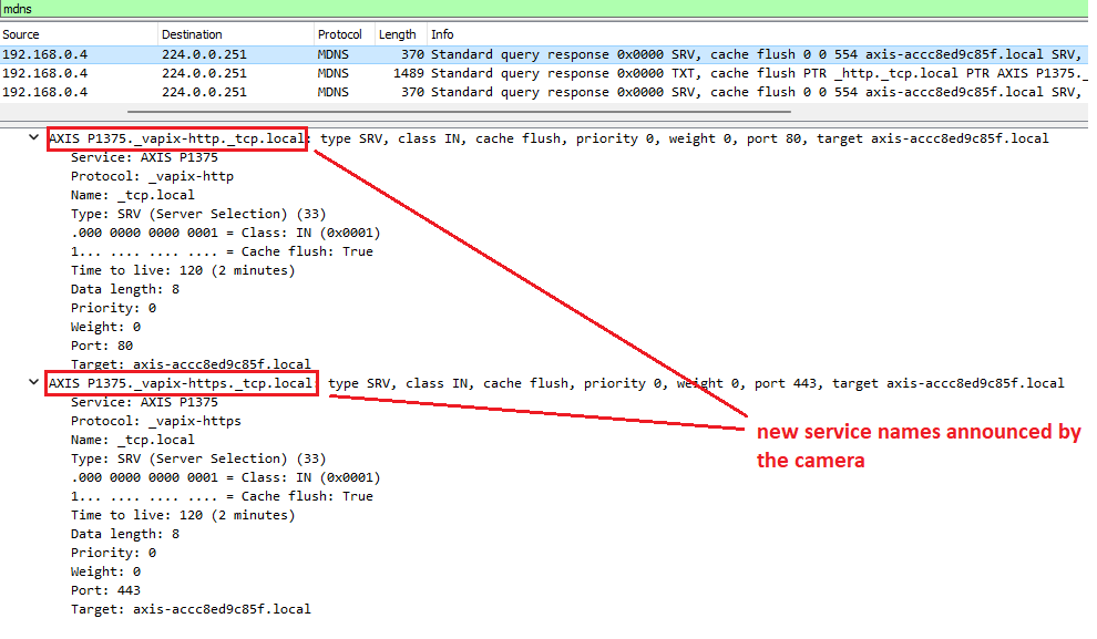
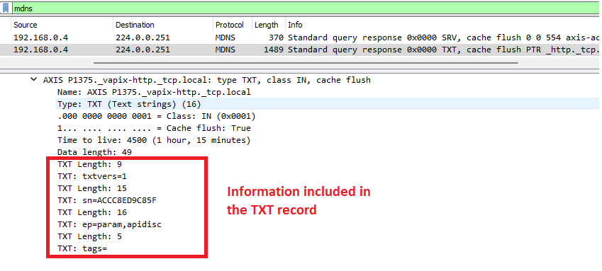
The devices are still announcing all the previous service names at the same time for the time being. So the VMSs and other clients should still be able to discover the Axis Devices, see below.
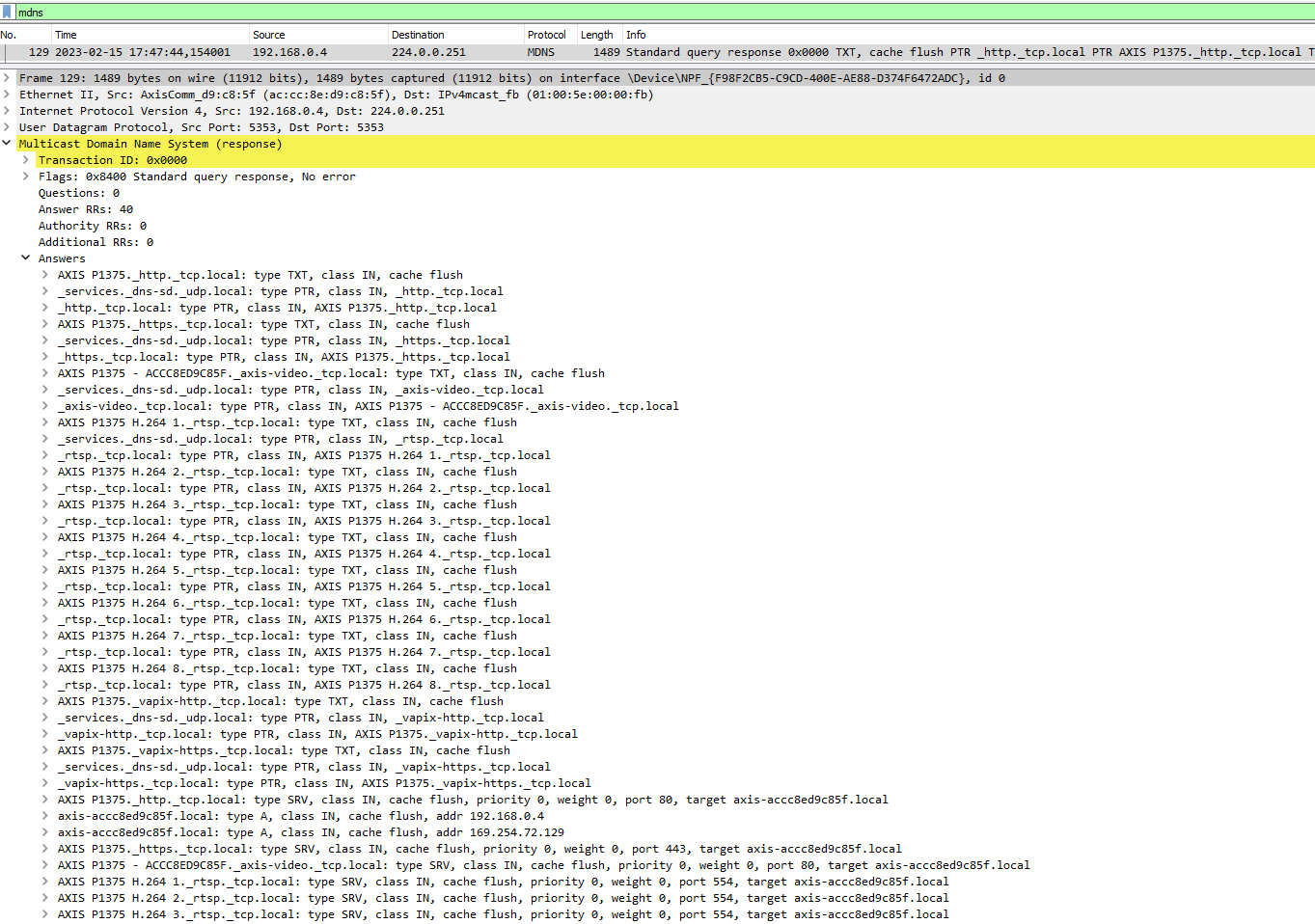
The default instance name (in the webpage, we call “Bonjour name” or “Friendly name”) can be changed when needed:
| AXIS OS version | Web interface configuration path | |||||||||||||||||||||||||||||||||||||||||||||||||||||||||||||||||||||||||||||||||||||||||||
| < 7.10 | Setup > System Options > Network > Bonjour | |||||||||||||||||||||||||||||||||||||||||||||||||||||||||||||||||||||||||||||||||||||||||||
| ≥ 7.10 | Settings > System > TCP/IP > Friendly name | |||||||||||||||||||||||||||||||||||||||||||||||||||||||||||||||||||||||||||||||||||||||||||
| ≥ 10.9 | System > Network > Network discovery protocols | |||||||||||||||||||||||||||||||||||||||||||||||||||||||||||||||||||||||||||||||||||||||||||
After changing the friendly name, it will apply to all services.
SNMP (Simple Network Management Protocol)
This section describes how to use Axis Video SNMP MIB. It’s assumed that you are familiar with the Simple Network Management Protocol (SNMP) already.
SNMP/MIBs allow network management operators to use standard SNMP tools to monitor the status of Axis products. The Axis Management Information Base (MIB) for video hardware enables monitoring of hardware-related issues that may need administrative attention. This applies to devices with AXIS OS 5.60 and higher. Note that new functionality may be added in later releases. For detailed information, read the MIB file.
Some products will not have all the hardware as specified below and there will only be one MIB defined for all hardware. In case the agent requests the status of hardware that is not included in the product, the device will return "noSuchObject". Which hardware is supported is handled at run time, meaning there is no need for product specific configuration. All Axis devices support the Axis Video MIB from AXIS OS 5.60 and higher except for AXIS Companion Line devices, however it’s recommended to update to the latest version. These MIBs are required to use Axis Video MIB:
SNMPv2–TC
SNMPv2–SMI
SNMPv2–CONF
AXIS-ROOT-MIB
AXIS-VIDEO-MIB
Enable SNMP
To use this functionality, SNMP must be enabled in the cameras and encoders on the network. SNMP in Axis devices can be enabled as below:
AXIS OS 6.5X and lower
SNMP can be enabled from the web interface using Setup > System Options > Network > SNMP.
AXIS OS 7.10 and higher
SNMP can be enabled from the web interface using Settings > System > SNMP.
To use SNMPv3, HTTPS has to be enabled. For information about how to enable HTTPS, see the user manual for the device.
You can use AXIS Device Manager to enable SNMP on multiple devices. AXIS Device Manager is available for download from www.axis.com.
SNMPv3 access
To enable SNMPv3 in Axis devices, a password must be set in the web interface for the default SNMP user initial. Once SNMPv3 is enabled, the following default privacy and authentication modes are pre-configured:
| AXIS OS | Privacy | Authentication |
| ≥12.8 | AES-128 or AES-256 | SHA-256 |
| > 11.0 | AES-128 | SHA-256 |
| ≥ 10.7 | AES-128 | SHA-1 |
| < 10.6 | DES | MD5 |
Note that it’s currently not possible for the user to change the default privacy and authentication modes in an easy way.
SNMP trap configuration
All Axis devices support the default SNMP MIB-II traps (Cold start, Warm start, Link up, Authentication failed). In addition, Axis devices support a number of feature and product specific traps that are included in Axis Video MIB (described in Axis Video MIB traps). Depending on your SNMP version, different configurations are required/available for using SNMP traps.
SNMPv1/v2c trap configuration
When SNMPv1 and SNMPv2c are used, all Axis Video MIB traps documented in Axis Video MIB traps will be enabled and sent when SNMP traps are enabled. The default MIB-II SNMP traps can be configured and enabled/disabled individually:
Cold start - sent when SNMP has been started and the configuration and MIB have changed
Warm start - sent when SNMP has been started and the configuration has changed, but not the MIB
Link up – sent when the network link changed from down to up
Authentication failed – sent when snmp-authentication attempt failed
SNMPv3 trap configuration
For SNMPv3, both the default MIB-II SNMP traps as well as the Axis Video MIB traps need to be configured and enabled manually. This is done using the SNMP-TARGET-MIB and SNMP-NOTIFICATION-MIB modules, defined in RFC 3413. So in order to configure the Axis device to send out SNMP traps, the following tables need to be configured accordingly:
snmpNotifyTable
snmpTargetAddrTable
snmpTargetParamsTable
snmpNotifyFilterProfileTable
snmpNotifyFilterTable
Axis Video MIB
Axis Video MIB (Message Information Base) extends the way to monitor Axis devices over SNMP. The Video MIB enables network administrators to monitor status information and a number of new notifications. To make use of the Axis Video MIB, download the MIB files here and import them in your SNMP network monitoring application. The Axis Video MIB is supported by Axis network devices from AXIS OS 5.60 and higher.
Axis Video MIB traps
There are only three kinds of traps that can be generated by a video product. These three kinds are defined in the Axis Video MIB and they should cover all the future needs of traps and thus they are defined in general terms. The trap types are described below:
alarmNew — This trap is sent to warn about a status change. Additional parameters include a unique trap ID (alarmID), a text string identifying the event (alarmName) and an additional string (alarmText) that specifies more detailed information about the event, for instance the unique identifier of the hardware or its status. This new state is valid until it is cleared by an alarmCleared trap. In general the state can be obtained through an SNMP get command as well.
alarmCleared — This trap is sent to indicate that some hardware has gone back to its normal state. The alarmID specifies the ID of a previous alarmNew trap that is cleared by this trap. Additional parameters include the same alarmName and alarmText that was sent by the alarmNew trap.
alarmSingle — This trap is sent to warn about a certain event. Additional parameters include a unique trap ID (alarmID), a text string identifying the event (alarmName) and an additional string (alarmText) that specifies more detailed information about the event, for instance the unique identifier of the hardware or its status. The difference from the alarmNew trap is that this trap refers to a stateless event. For this reason there is no alarmCleared and hence several traps indicating the same event might follow each other. Since this is a stateless event it is impossible to get any related information through SNMP get command.
| Trap name/use case | Trap type | Alarm name | Alarm cleared event* | Supported products |
| (Multiple) Power Supply Failure | alarmNew | powerSupplyAlert | ✓ | AXIS Q7900 Rack and AXIS Q7920 Video Encoder Chassis |
| (Multiple) Fan Failure | alarmNew | fanAlert | ✓ | AXIS Q7900 Rack and AXIS Q7920 Video Encoder Chassis |
| (High or Low) Temperature Limit Reached Alert | alarmNew | temperatureAlert | ✓ | All Axis devices |
| (Multiple) Analog Video Signal Lost | alarmNew | videoSignalAlert | ✓ | Axis video encoders, with AXIS OS 5.60 — 6.50 |
| (Multiple) Audio Input Signal Lost | alarmNew | audioSignalAlert | ✓ | All Axis audio-capable devices with external audio input |
| Product Casing Opened Alert | alarmNew | openCasingAlert | ✓ | All Axis devices connected with AXIS T93F door switch / intrusion alarm |
| Mechanical PTZ Error Alert | alarmSingle | PTZAlert | ✓ | All Axis mechanical PTZ devices |
| Edge Storage Alert | alarmNew | storageMediaAlert | ✓ | All Axis devices featuring SD cards and mounted network share |
| Camera Tampering Alert | alarmSingle | tamperingAlert | All Axis tampering-capable devices (does not apply to AXIS Image Health Analytics) | |
| General Trap | alarmNew or alarmSingle** | Custom AlarmText | All Axis devices |
*The alarm cleared event is sent automatically. E.g. if the Axis device detects an issue with the storage devices, it will send out an alarm, and if the issue resolved itself, it will send another alarm notifying that the issue is resolved.
**Depending on whether the event is stateless or stateful the trap is of type alarmNew or alarmSingle
Axis Video MIB OIDs
The status operations that are available in the AXIS SNMP MIB are listed below. All statuses are read-only objects. If a set operation is requested on the OID it will return 17, notWritable (or 2,nosSuchName, for protocol version 1). A status operation can have one or more OIDs depending on the product. As an example, .1.3.6.1.4.1.368.4.1.1.1.3.x can be .1.3.6.1.4.1.368.4.1.1.1.3.1 Temperature Sensor 1, .1.3.6.1.4.1.368.4.1.1.1.3.2 Temperature Sensor 2, .1.3.6.1.4.1.368.4.1.1.1.3.3 Temperature Sensor 3, and so on.
| OID Name | OID | Possible OID States | Supported products |
| Get Power Supply Status | .1.3.6.1.4.1.368.4.1.1.1.3.x | OK;Failure | AXIS Q7900 Rack and AXIS Q7920 Video Encoder Chassis |
| Get Fan Status | .1.3.6.1.4.1.368.4.1.2.1.3.1.x | OK;Failure | AXIS Q7900 Rack and AXIS Q7920 Video Encoder Chassis |
| Get Temperature Sensor Value | .1.3.6.1.4.1.368.4.1.3.1.4.1.x | Temperature in degree celsius | All Axis devices |
| Get Temperature Sensor Status | .1.3.6.1.4.1.368.4.1.3.1.3.1.x | OK;Failure;OutOfBoundary | All Axis devices |
| Get Video Signal Status | .1.3.6.1.4.1.368.4.1.4.1.2.x | SignalOK;NoSignal | All Axis video encoders |
| Get Audio Signal Status | .1.3.6.1.4.1.368.4.1.5.1.2.x | SignalOK;NoSignal | All Axis audio-capable devices |
| Get Casing Status | .1.3.6.1.4.1.368.4.1.6.1.3.x | Open;Closed | All Axis devices connected with AXIS T93F door switch / intrusion alarm |
Get Storage Disruption Status | .1.3.6.1.4.1.368.4.1.8.1.3.x | Yes;No | All Axis devices |
Axis Video MIB Tree
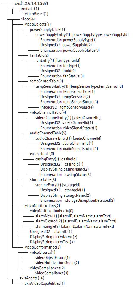
Import Axis Video MIB files using iReasoning MIB Browser
The screenshots below illustrates how to import Axis Video MIB files into the iReasoning MIB Browser.
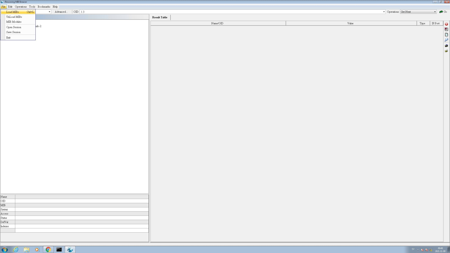
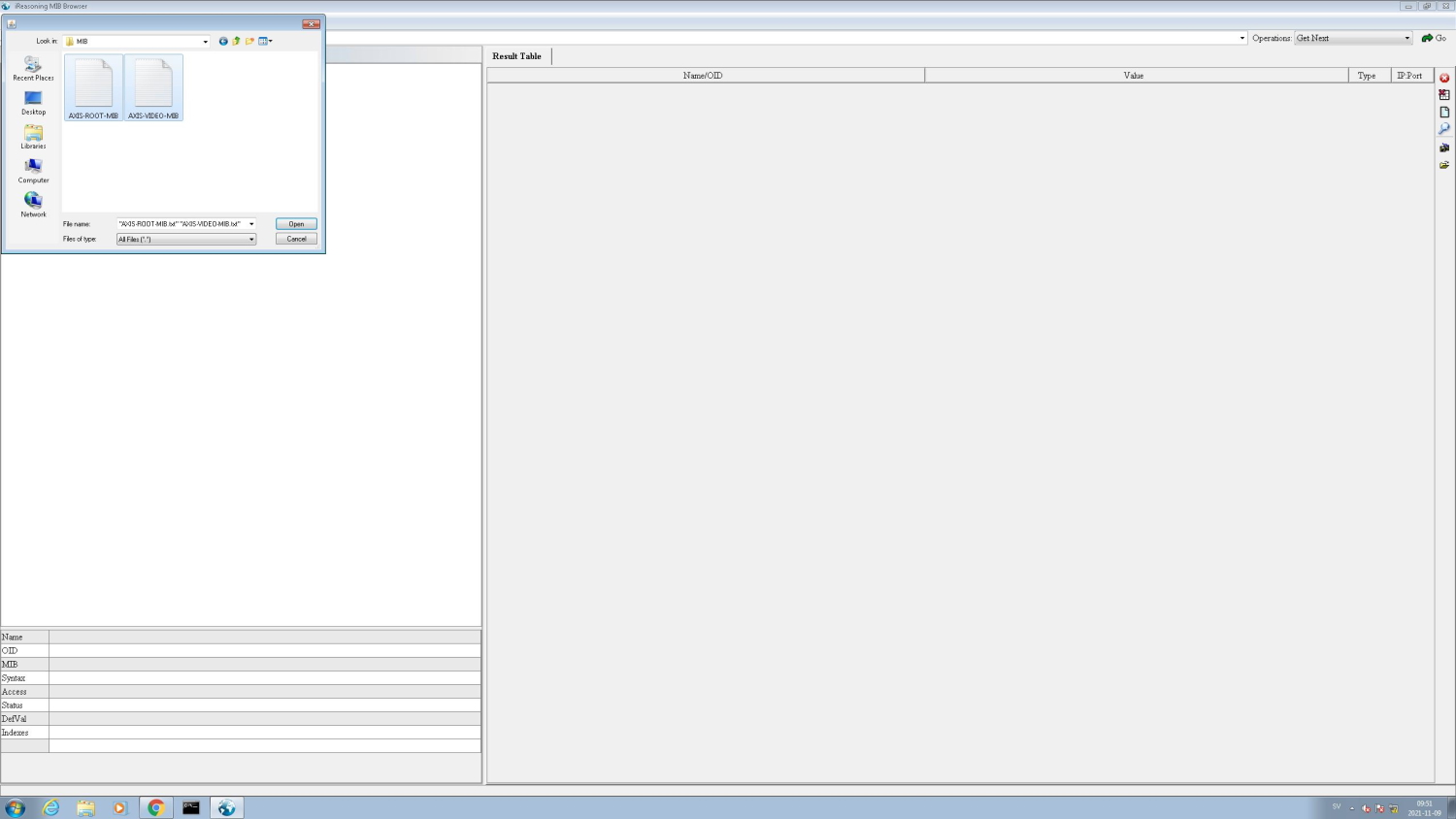
SNMP walk using iReasoning MIB Browser
The screenshots below illustrate how to do an SNMP walk on an Axis device. Note that SNMP needs to be enabled.
SNMPv1/2
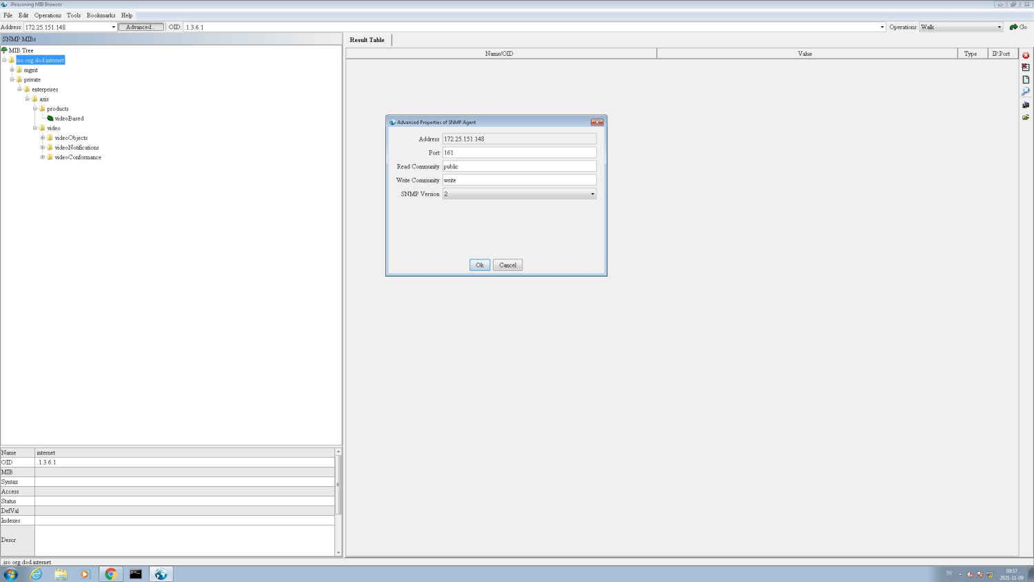
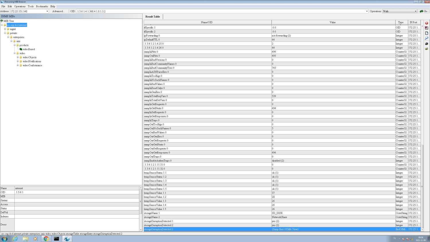
SNMPv3
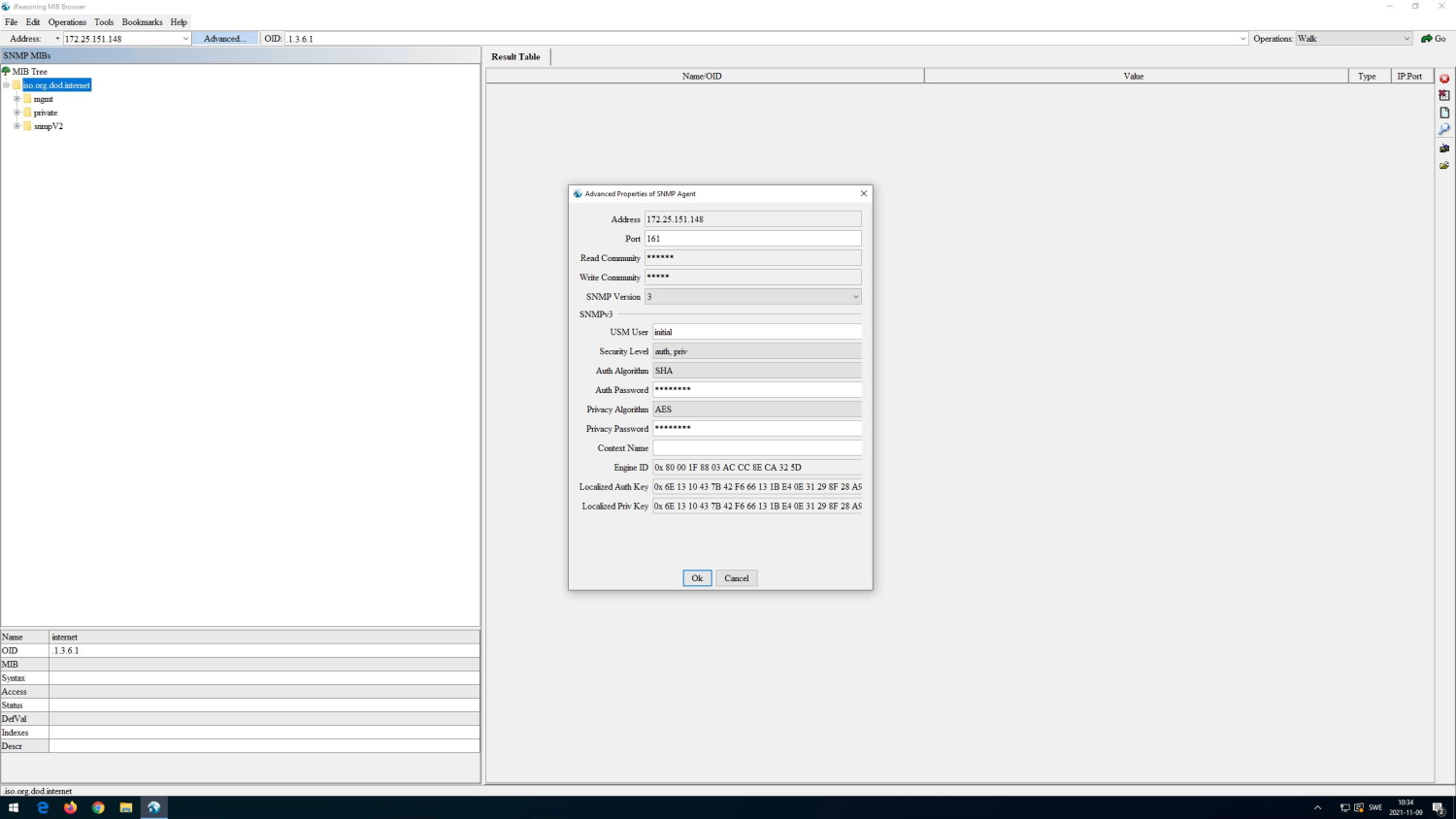
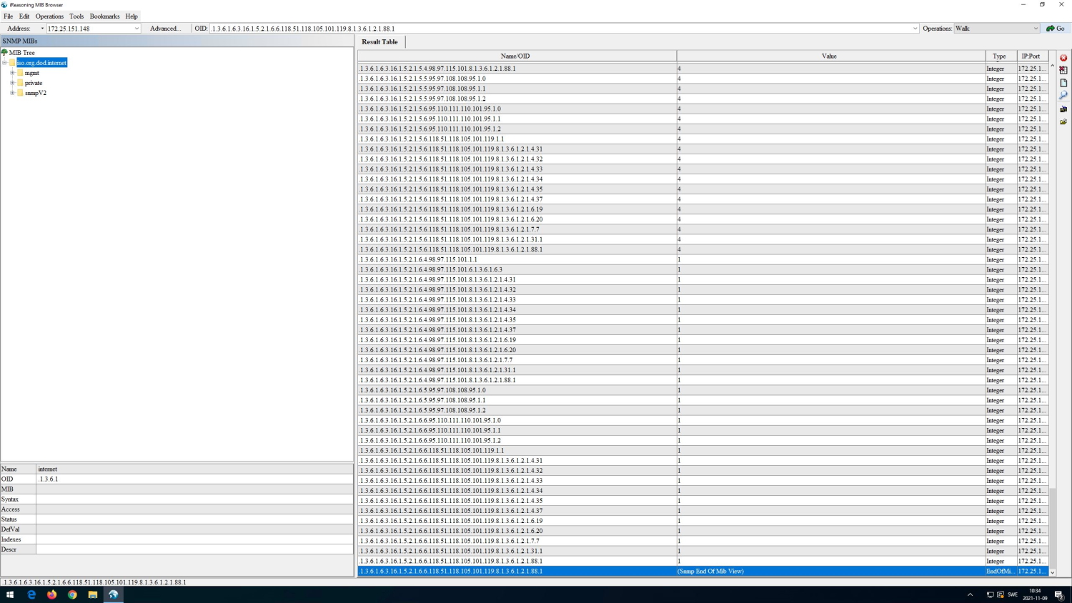
Receiving SNMP traps using iReasoning MIB Browser
The screenshots below illustrate how to receive an SNMP trap from an Axis device. Note that SNMP traps need to be enabled.
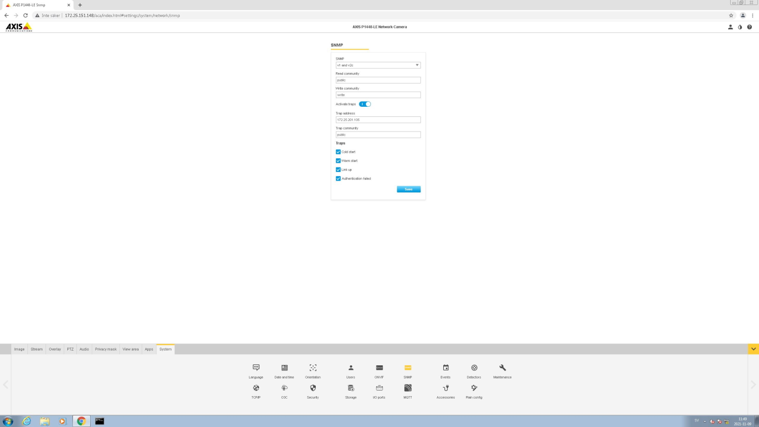
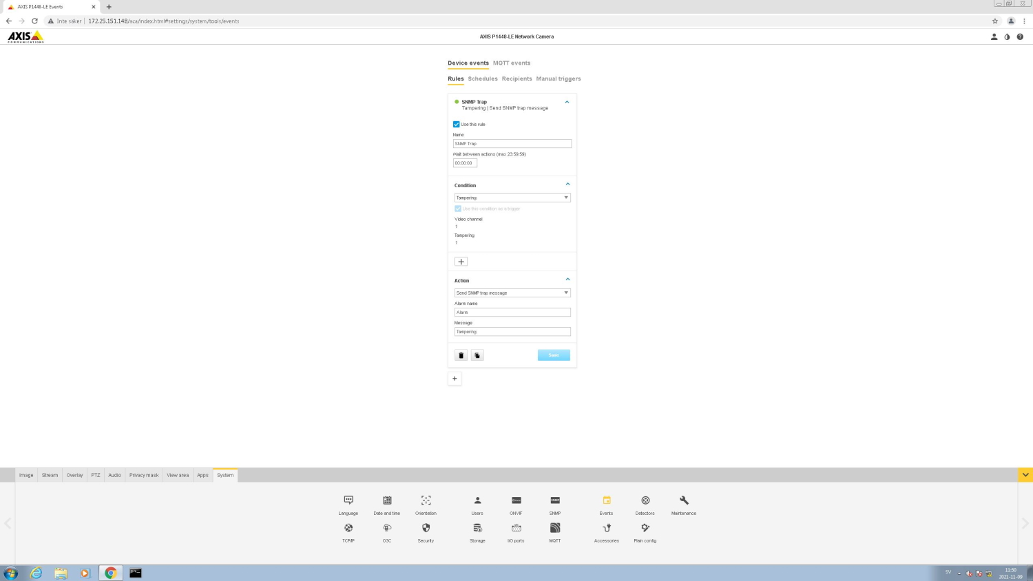
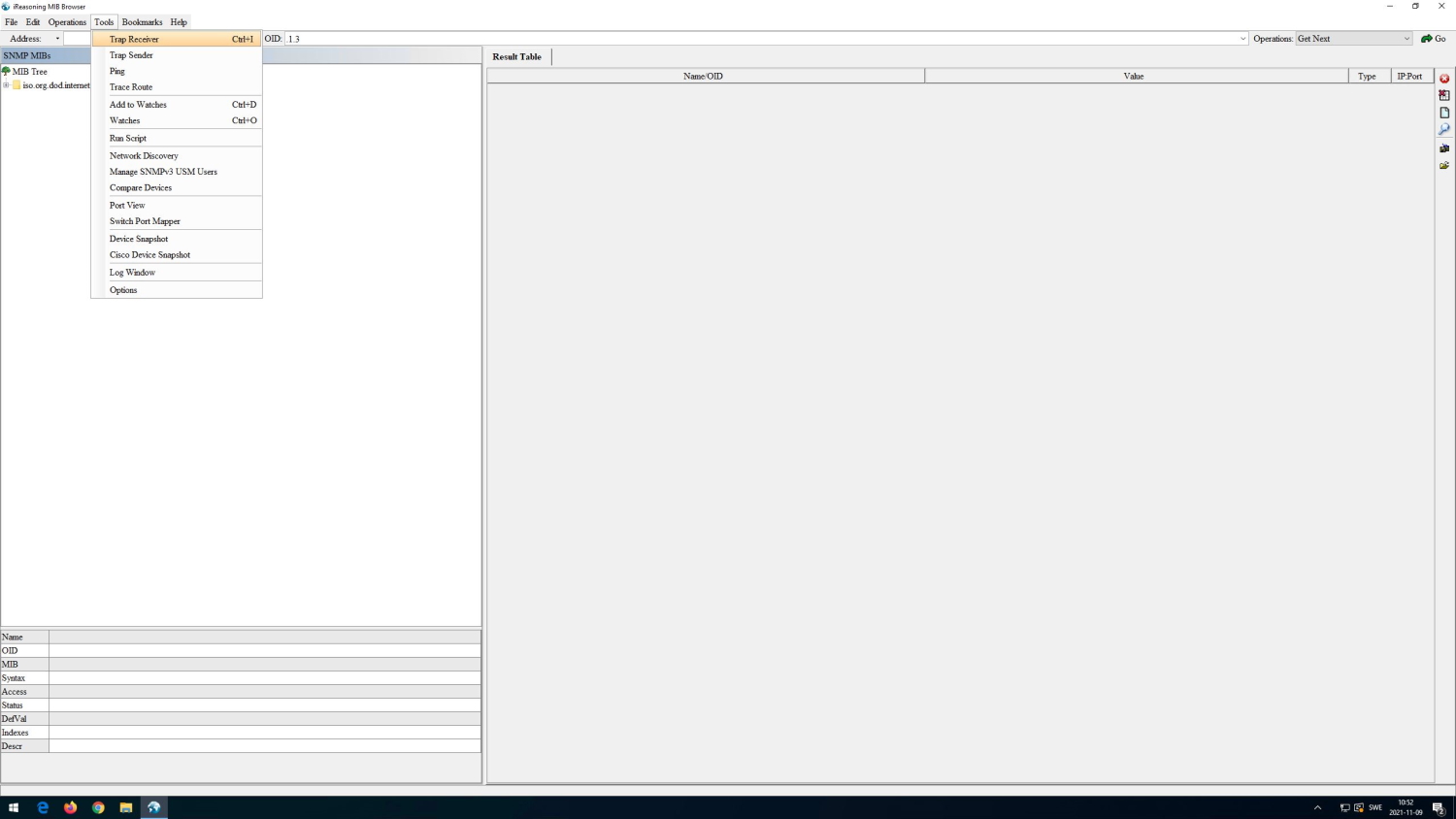
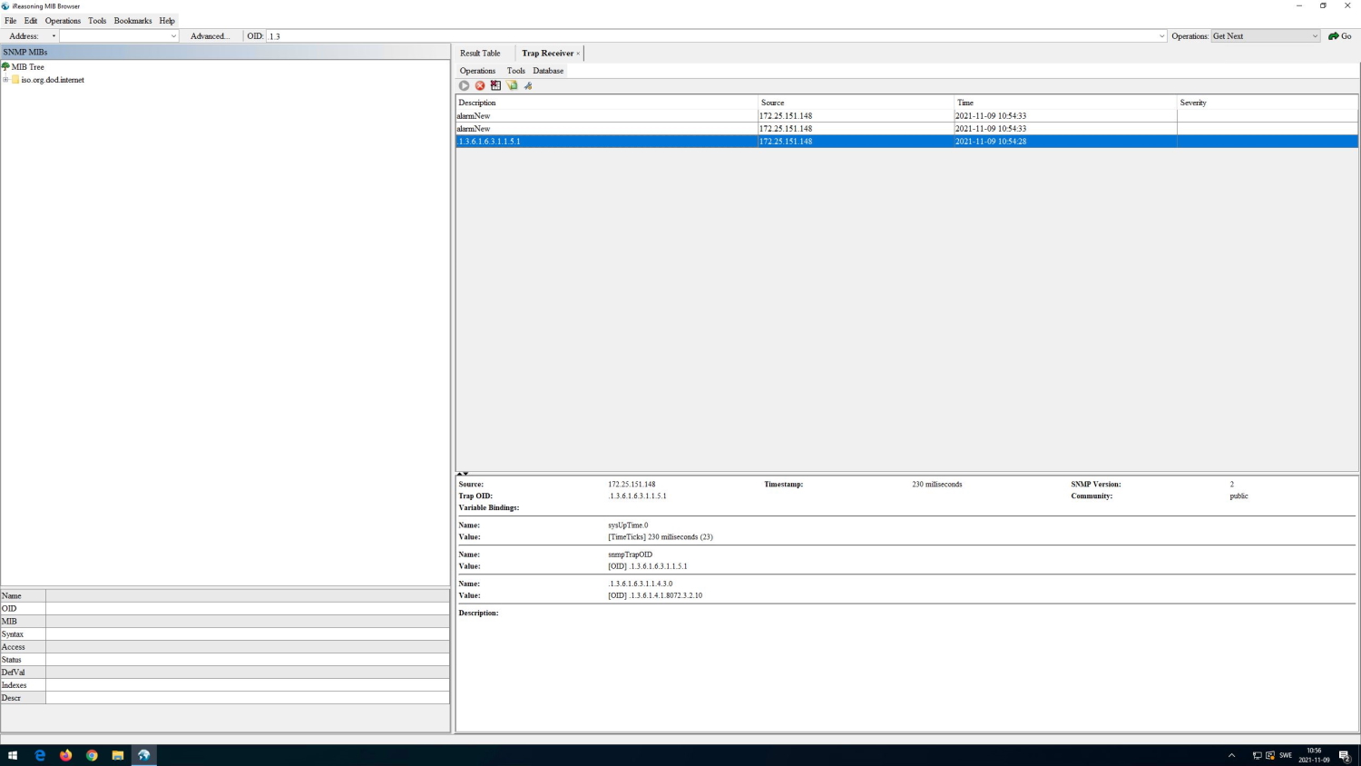
LLDP (Link Layer Discovery Protocol)
All Axis devices with AXIS OS 7.10 and higher are utilizing LLDP (Link Layer Discovery Protocol) to neighbor-announce their identity and capabilities information using the TLV-encoding scheme (Type-Length-Value) in the network. When sending out LLDP announcements, it is possible to configure certain information such as system description and name of the device. In order to configure specific LLDP settings, you can access the device via SSH, SSH is disabled per default and can be enabled in Settings > System > Plain config > Network. Once SSH access is established, type "lldpcli". See the following instructions for further commands that can be used in the LLDPCLI.
In addition to neighbor announcements, LLDP can also be used for software-based PoE negotiation. IEEE 802.3at (30 W PoE+) capable devices support software-based PoE negotiations, and IEEE 802.3af (15.4 W) capable devices running AXIS OS 9.20 and higher support the LLDP allocation of max-power towards the connected PoE-switch. When enabled, the Axis device will notify the PoE-switch about its max PoE consumption so that the PoE-switch can perform a better PoE-management and allocate less PoE to the network port. LLDP allocation for max-power can be enabled in Settings > System > Plain config > Network > LLDP POE > LLDP Send Max PoE. Both methods utilize the LLDP Dot3 PoE-MDI TLV.
When LLDP allocation for max-power is enabled in the Axis device, and the network switch is configured properly in regards to LLDP- and PoE-mode according to vendor documentation, the network switch should be able to reserve the exact amount of max PoE wattage that the Axis device would need. The example below illustrates the behavior of LLDP allocation for max-power being enabled and disabled in an Axis device.
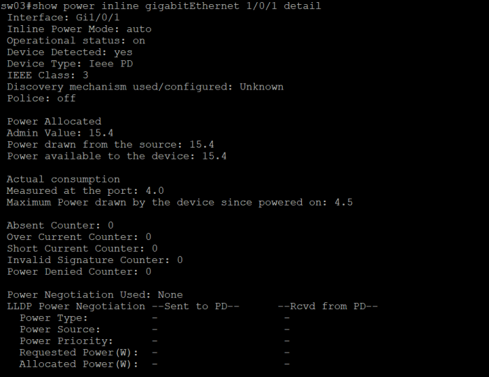
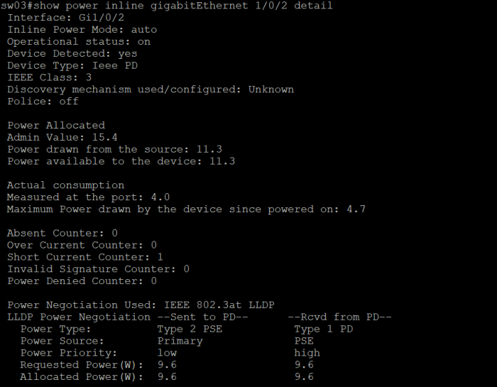
When LLDP allocation for max-power is disabled, the network switch will reserve the full amount of 15.4 W PoE according to IEEE 802.3af with no savings gained. Compare this with having the LLDP allocation for max-power enabled, which will result in the network switch reserving in total 11.3 W PoE instead, where 9.6 W results from the needs of the Axis device and the additional 1.7 W is a margin for power loss due to cable length. This improved PoE management results in saving 4.1 W PoE that can be used on a different network port on the same network switch.
Media Endpoint Discovery (LLDP-MED)
LLDP-MED (Media Endpoint Device Extension) is an extension on top of the LLDP protocol stack that allows devices to include more information (TLVs) during LLDP exchange with network neighbors. At the time of writing (December 2020), Axis devices do not support LLDP-MED extensions and therefore do not support e.g. the LLDP-MED POE-MDI TLV for PoE power negotiation.
Fabric Attach
Fabric Attach (FA) is a technology developed by Extreme Networks. It comes with an Autonomic Edge capability which simplifies the addition of new devices to the network. Axis devices with AXIS OS 12.1 or later have the Basic Fabric Attach client capability, which reduces the time and cost to deploy them in Extreme Networks with “Zero-Touch”. For a complete list of products supporting Fabric Attach, please refer to Products on active track in AXIS OS Release notes.
Fabric Attach uses the Link Layer Discovery Protocol (LLDP) with custom organizational Type-Length-Values (TLVs) to automate the onboarding process for network devices onto different networks or services. As a Basic Fabric Attach client, Axis devices generate a Fabric Attach Element TLV which includes the following properties:
Fabric Attach Element type
A System ID with the device's MAC Address
The screenshot below provides a closer look at the LLDP packet structure for an Axis device.
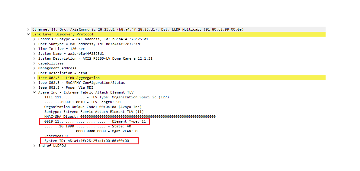
The following applies for all Axis devices:
Fabric Attach Element Type is always set to 11 (IP camera).
System ID contains your device’s unique MAC address.
LLDP is enabled by default.
The FA Element TLV is included in every outgoing LLDP packet.
Extreme Networks has four FA client variants. Axis devices act as Basic FA clients with minimal implementation, which allows you to bypass authentication for the FA Element TLV. As a result, the HMAC-SHA digest value is always zero.
Example setup
In this scenario, the customer has a dedicated network segment, VLAN 202.
Previously, to onboard a camera, the customer would connect it to a physical switch port and then manually assign that port to VLAN 202. Fabric Attach simplifies the onboarding process.
By default, all ports on the Extreme Networks Fabric Engine switch are set for auto-sense.
The customer connects the Axis device to Port 2, which has Fabric Attach enabled. Once the device is powered on, it starts sending LLDP packets.
Using the FA Element TLV, the switch identifies the device as an IP Camera and automatically moves Port 2 to VLAN 202 with no manual intervention required.
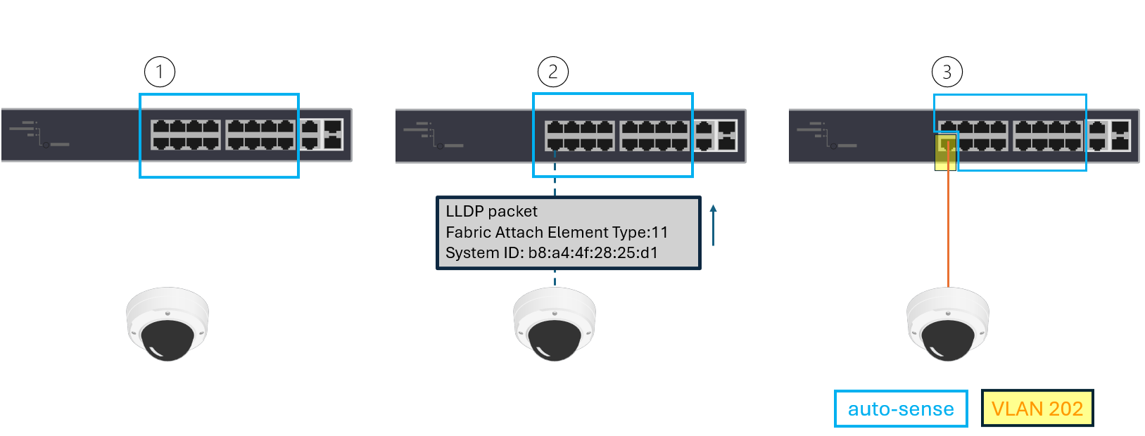
To verify the Fabric Attach status on the Extreme Network switch:
SW24.14 # show fabric attach elements
Fabric Attach Mode: Standalone Proxy
                                                       Mgmt     Auto
System Id                     Port    Type             VLAN Tag Provision
----------------------------- ------- ---------------- ---- --- --------------
b8-a4-4f-28-25-d1-00-00-00-00 2       IP Camera        None Mix Disabled
SW24.15 # show fabric attach assignments
Fabric Attach Mode: Standalone Proxy
Port VLAN VLAN Name Type ISID/NSI Status
------- ---- -------------------------------- ------- -------- --------
202 VLAN_0202 Static N/A Active
2 202 VLAN_0202 ZTC N/A ActiveThe type ZTC stands for Zero Touch Client. The minimal configurations of Fabric Attach have been included below for reference.
configure fabric attach uplink 24
configure fabric attach zero-touch-client camera vlan VLAN_0202 nsi 12345
configure fabric attach zero-touch-client camera enable
configure vlan VLAN_0202 add nsi 12345
CDP (Cisco Discovery Protocol)
All Axis devices with AXIS OS 8.50.1 and higher are utilizing the CDP (Cisco Discovery Protocol) protocol to announce their identity and capabilities in the network. Compared to the LLDP protocol, no CDP traffic is sent out from the Axis device by default unless the network switch initiates CDP communication first.
CDP is also used for power negotiation in IEEE 802.3at (30W PoE+) capable devices. By default, the Axis device is capable of power negotiating IEEE 802.3at (30W PoE+) either using CDP or LLDP. Which one of these protocols is used depends on the network switch configuration.
In a situation where both protocols are being enabled and used by the network switch, the Axis device will respond to the protocol that arrives first (first come, first served). Note that Cisco 60W UPoE power negotiations are not supported regardless if they are hardware- or software-based.
Syslog
Syslog is a standard for message logging in IT devices. It is increasingly required in IT business applications and governance to facilitate, store, monitor and analyze audit logs from IT devices. The syslog standard is based on RFC 3164 and the newer RFC 5424. Axis devices are compliant with both standards in order to allow for an easy and simple integration towards 3rd party syslog servers such as Nagios, PRTG, Syslog-NG- or Rsyslog-based syslog servers. The common term used for edge devices sending their log messages to a syslog server is referred to as “remote logging” or “remote syslogging”. When it comes to syslog, there are two different types of devices in a network working together:
Edge device: An edge device with support for syslog generates log messages which are sent to a centralized server. The edge device in itself, however, may have limited amount of system resources to keep log messages long enough, or the messages may be overwritten or erased automatically upon reboot. Axis devices are examples of edge devices.
Syslog server: The syslog server is a centralized entity in the network that receives syslog messages from edge devices and facilitates and stores them in a manner that allows for real-time analysis and/or auditing. Different types of syslog servers are available and range from simple servers that “just” store incoming syslog messages up to fully-fledged enterprise-class syslog servers providing all means for real-time analysis as well as auditing with notification backend.
In order to send log messages to the syslog server, the edge device and server need to communicate using the same protocol/port. The edge device also needs to be configured so that it sends log messages with the desired severity.
Protocol/ports: The syslog standard is based on RFC 3164 and the newer RFC 5424. The default ports that are used are UDP port 514 and TCP port 601 as well as encrypted transport via SSL/TLS port 6514. With AXIS OS 11.6 and later, we introduced our own proprietary format called “Axis” format that is mainly for our internal use. It’s the same format that we currently using in our server report logs. Please be noted that Axis may change this format without prior notice.
Log message severity: Log messages are categorized in severities based on importance, from low to high. In newer AXIS OS versions, it is possible to define from which severity level the Axis device will send log messages to a remote syslog sever. See log message severities for Axis devices below:
DEBUG – INFO – NOTICE – WARNING – ERROR – CRITICAL – ALERT – EMERGENCY
Examples of log messages from an Axis device
RFC 3164
<8>Aug 23 16:32:18.000 axis-b8a44f18d105 remote-syslogd: remote-syslogd-test: This is Emergency message
<9>Aug 23 16:32:18.000 axis-b8a44f18d105 remote-syslogd: remote-syslogd-test: This is Alert message
<10>Aug 23 16:32:18.000 axis-b8a44f18d105 remote-syslogd: remote-syslogd-test: This is Critical message
<11>Aug 23 16:32:18.000 axis-b8a44f18d105 remote-syslogd: remote-syslogd-test: This is Error message
<12>Aug 23 16:32:18.000 axis-b8a44f18d105 remote-syslogd: remote-syslogd-test: This is Warning message
RFC 5424
<8>1 2023-08-23T16:34:23.000+02:00 axis-b8a44f42b8b0 remote-syslogd - - - remote-syslogd-test: This is Emergency message
<9>1 2023-08-23T16:34:23.000+02:00 axis-b8a44f42b8b0 remote-syslogd - - - remote-syslogd-test: This is Alert message
<10>1 2023-08-23T16:34:23.000+02:00 axis-b8a44f42b8b0 remote-syslogd - - - remote-syslogd-test: This is Critical message
<11>1 2023-08-23T16:34:23.000+02:00 axis-b8a44f42b8b0 remote-syslogd - - - remote-syslogd-test: This is Error message
<12>1 2023-08-23T16:34:23.000+02:00 axis-b8a44f42b8b0 remote-syslogd - - - remote-syslogd-test: This is Warning message
Axis format
2023-08-23T16:30:14.998+02:00 axis-b8a44f4645f4 [ EMERG ] remote-syslogd[209665]: remote-syslogd-test: This is Emergency message
2023-08-23T16:30:14.998+02:00 axis-b8a44f4645f4 [ ALERT ] remote-syslogd[209665]: remote-syslogd-test: This is Alert message
2023-08-23T16:30:14.998+02:00 axis-b8a44f4645f4 [ CRIT ] remote-syslogd[209665]: remote-syslogd-test: This is Critical message
2023-08-23T16:30:14.998+02:00 axis-b8a44f4645f4 [ ERR ] remote-syslogd[209665]: remote-syslogd-test: This is Error message
2023-08-23T16:30:14.998+02:00 axis-b8a44f4645f4 [ WARNING ] remote-syslogd[209665]: remote-syslogd-test: This is Warning message
Syslog in Axis devices
Axis devices have been compliant with the syslog standard since its implementation in the 2000s. As such, Axis devices have throughout the years been supporting syslog in various ways in order to adapt, always using the newest implementation:
| Implementation | SYSKLOGD | RSYSLOG | SYSLOG-NG MK I | SYSLOG-NG MK II |
| Supported versions | ≤ 5.55 | 5.60 - 6.50 | 7.10 - 10.0 | 10.1 ≥ |
| Script editor configuration | ✓ | ✓ | ✓ | |
| Web interface configuration | ✓ | |||
| VAPIX API configuration | ✓ | |||
| SD card or network share storage* | ✓ | ✓ | ||
| Transport protocol | UDP | TCP/UDP | TCP/UDP | TCP/UDP/TLS |
| Primary & secondary remote syslog server** | ✓ | |||
| Send log messages test button*** | ✓ | |||
| Log severity configuration**** | ✓ |
* Optional support for saving syslog messages to the local SD card or network share.
** Possibility to configure a primary and secondary remote syslog server. When both are configured, the Axis device will send its log messages simultaneously to both servers. Observe that this is not a failover-configuration.
*** Possibility to send test messages to the remote syslog server in order to verify correct configuration.
**** Possibility to configure the Axis device to send log messages with a specific severity and higher only.
The coming sections will show example configurations that can be accomplished illustrated with the different syslog implementations that Axis devices have supported throughout the years.
Syslog configuration in AXIS OS 10.1
Web interface
Devices with AXIS OS version 10.1 and higher have a graphical user interface for syslog configuration. This can be found via the web interface of the device.
AXIS OS version | Web interface configuration path |
≥ 10.1 | Settings > System > TCP/IP |
≥ 10.9 | System > Logs |
Remote syslog via UDP: 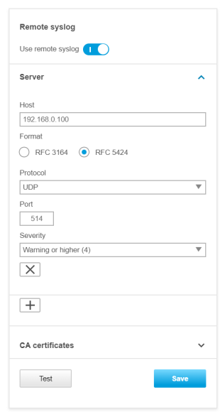 | Remote syslog via TCP: 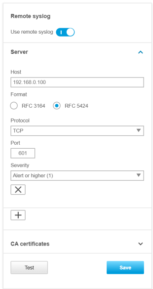 |
Remote syslog via TCP/TLS*: 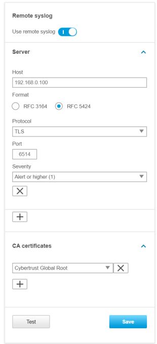 | Remote syslog via TCP/TLS (primary + secondary)**: 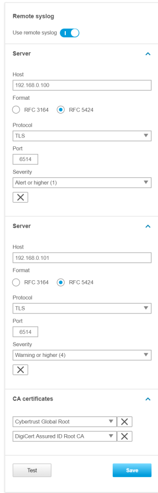 |
* For the TLS mode you need to specify a CA certificate that will be used by the Axis device to verify the remote syslog server. This CA certificate is generated and provided during the configuration of the 3rd party remote syslog server.
** When a primary and secondary syslog server is configured, the Axis device will always send its log messages simultaneously to both servers independently regardless if the primary, secondary, or both servers are available.
See the sample illustrations below of an Axis device streaming its syslog messages to either a primary server only, or a primary/secondary server in parallel.
VAPIX interface (VAPIX API)
Devices with AXIS OS version 10.1 and higher also support the Remote Syslog API VAPIX interface that allows for mass-configuration of Axis devices e.g. using AXIS Device Manager. For more information, go to the VAPIX library.
AXIS Device Manager
With the introduction of the new Remote Syslog API, it’s also possible to configure remote syslog settings for multiple Axis devices simultaneously.
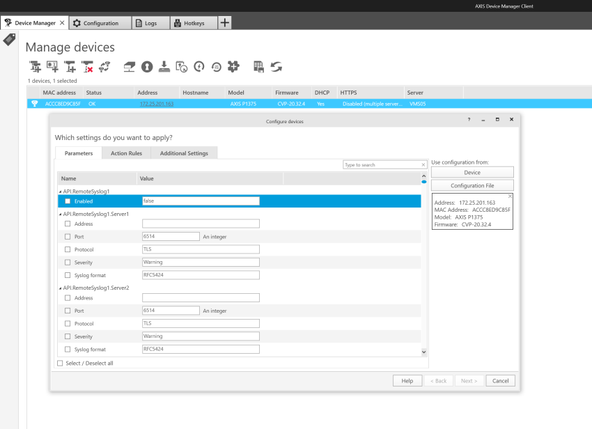
Syslog configuration in AXIS OS 7.10 - 10.0
Script editor
In order to configure remote syslog server, the script editor needs to be enabled. This can be done via the web interface of the Axis device, under Settings > System > Plain config > System > Enable the script editor (editcgi).
To configure syslog, open the following link in the browser, replace the IP adress placeholder ("ip_of_cam") with the real IP address of the Axis device: http://ip_of_cam/admin-bin/editcgi.cgi?file=/etc/syslog-ng.d/remote.conf
Add IP address, transport method and port as you see in the below example configuration. Click Save file once done and restart the device.
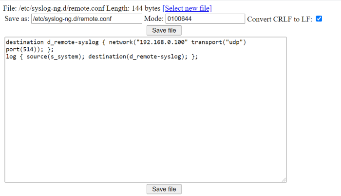
Make sure that no code line is out commented by a hash symbol ("#") like in the example configuration above.
Syslog configuration in AXIS OS 5.60 - 6.50
In order to configure syslog, open the following link in the browser and replace the IP address placeholder (i.e. "ip-address") with the real IP address of the Axis device: http://ip-address/admin-bin/editcgi.cgi?file=/etc/rsyslog.d/40-remote_log.conf
Remote syslog server
Add *.* @ip-address at the bottom of the configuration file and specify the real IP address of the remote syslog server instead. Click Save file once done and restart the device.
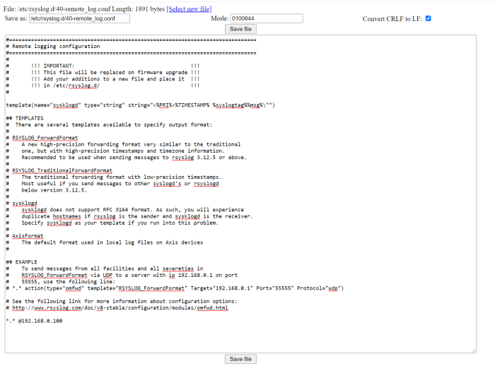
SD card
Start by mounting an SD card in the Axis device. Then add *.* /var/spool/storage/SD_DISK/logs.txt at the bottom of the configuration file. Click Save file once done and restart the device.
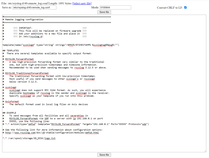
Network share
Start by mounting a network share on the Axis device. Add *.* /var/spool/storage/NetworkShare/logs.txt at the bottom of the configuration file. Click Save file once done and restart the device.
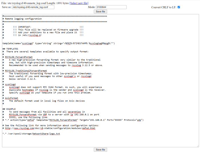
Syslog configuration in AXIS OS 5.55 and below
In order to configure syslog, open the following link in the browser, replace the IP address placeholder (i.e. "ip-address") with the real IP address of the Axis device: http://ip-address/admin-bin/editcgi.cgi?file=/etc/syslog.conf.
Remote syslog server
Start by adding *.* @ip-address at the bottom of the configuration file and specify the real IP address of the remote syslog server instead. Click Save file once done and restart the Axis device.
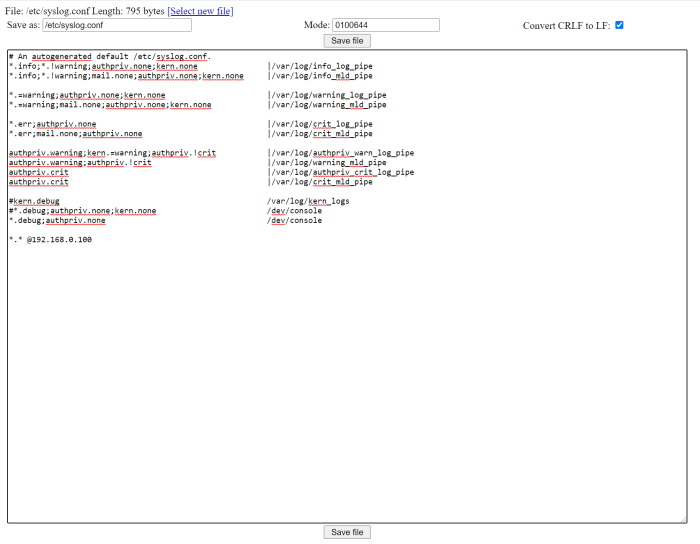
SD card
Start by mounting an SD card in the Axis device. Then add *.* /var/spool/storage/SD_DISK/logs.txt at the bottom of the configuration file. Click Save file once done and restart the Axis device.
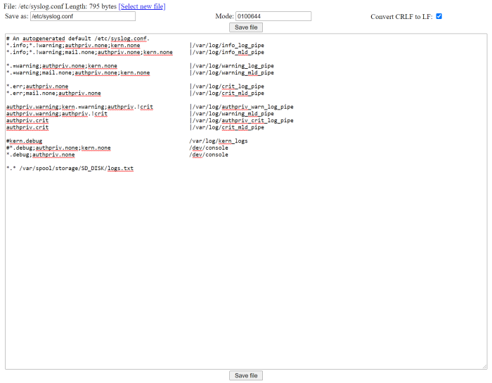
Network share
Start by mounting a network share on the Axis device. Then add *.* /var/spool/storage/NetworkShare/logs.txt at the bottom of the configuration file. Click Save file once done and restart the Axis device.
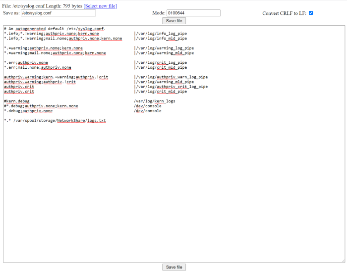
About syslog server support
Axis devices are compliant with the syslog standard that is based on RFC 3164 and the newer RFC 5424, so the transmission of syslogs to a server should work out-of-the-box when configured correctly. Axis devices are tested regularly with different syslog servers such as syslog-ng, rsyslog as well as PRTG Paessler, Nagios, QNAP and Synology.
Below is a sample image of an Axis device sending log messages to a Nagios syslog server.
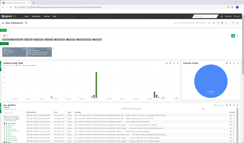
MQTT
MQTT is a machine-to-machine (M2M)/Internet of things (IoT) connectivity protocol. It was designed as an extremely lightweight publish/subscribe messaging transport and is useful for connections with remote locations where a small code footprint is required and/or network bandwidth is at a premium.
MQTT is quickly becoming the standard communication protocol for implementing IoT solutions due to its lightweight and bandwidth-efficient characteristics. You can read more about benefits and usecases in the whitepaper Device integration with MQTT or keep on reading to learn more about configuring MQTT, starting with the most important components.
Client
Any publisher or subscriber that connects to a centralized server/broker over a network is a client. Both publishers and subscribers are called clients since they connect to a centralized service. Clients can be persistent or transient. Persistent clients maintain a session with the server/ broker while transient clients are not tracked by the server/ broker. Clients often connect to the server/ broker through libraries and SDKs.
Server/broker
The server/broker is the software that receives all the messages from the publishing clients and sends them to the subscribing clients. It holds the connection to persistent clients. Since the server/broker can become a bottleneck or result in a single point of failure, it is often clustered for scalability and reliability. It is up to the implementor to decide how to create a scalable server/broker infrastructure. Some of the commercial implementations of MQTT brokers include HiveMQ, Xively, AWS IoT and Loop.
Topic
A topic in MQTT is an endpoint information that a client (publisher) can share, and another client (subscriber) can connect to. Topics are simple, hierarchical strings, encoded in UTF-8, delimited by a forward slash. For example, "building1/room1/temperature" and "building1/room1/humidity" are valid topic names.
Connection
MQTT can be utilized by clients based on TCP/IP. The standard port exposed by servers/brokers is 1883, which is not a secure port. Servers/brokers that support TLS/SSL typically use port 8883. For secure communication, the clients and the server/broker rely on digital certificates.
Functionality overview
Axis devices with AXIS OS version 9.80 and above support the MQTT protocol to allow customers and the market to deepen the integration of their business and system applications. In the table you can see the functionality that is currently supported as well as upcoming functionality.
| Functionality | AXIS OS version |
| Generic MQTT event publishing | AXIS OS 9.80.1 |
| Custom MQTT event publishing | AXIS OS 10.4.0 |
| Custom MQTT event subscription | AXIS OS 10.6. Added to web interface in AXIS OS 10.7 |
| MQTT web interface support | AXIS OS 10.1 |
| MQTT over TCP | AXIS OS 9.80.1 |
| MQTT over SSL | AXIS OS 9.80.1 |
| MQTT over WebSocket | AXIS OS 9.80.1 |
| MQTT over WebSocket (SSL) | AXIS OS 9.80.1 |
| MQTT VAPIX API | AXIS OS 9.80.1 |
| MQTT ALPN support (Application-Layer Protocol Negotiation) | AXIS OS 10.9.0 |
| MQTT Overlay Support | AXIS OS 11.4 |
In the following sections you can read more about configuring a device via the web interface.
Server
These examples show you how to configure an Axis device to connect to an MQTT server/broker in the web interface. To connect, the user must specify the server’s/broker’s IP address or hostname, the transport protocol and port, as well as credentials (i.e. username and password). The MQTT server/broker connection configurations can be found under Settings > System > MQTT in the web interface.
| Example configuration: MQTT over TCP
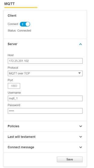 | Example configuration: MQTT over SSL*
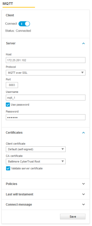 |
*For the MQTT over SSL connection to be successful the CA and client certificate must be available under Settings > System > Security so that they can be selected in the MQTT configuration.
Policies
The connection policies help the user define general MQTT connection behavior of the Axis device towards the MQTT server/broker it connects to. Below you will find a more detailed description of the individual settings of the policies.
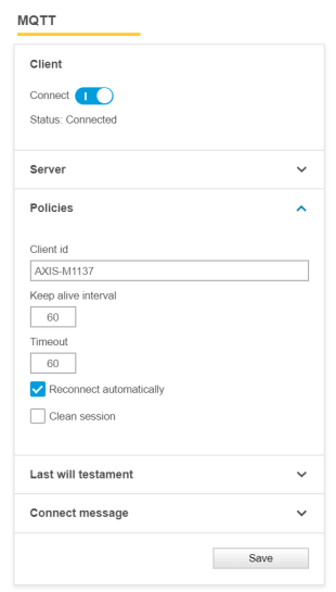
Client id: nice/nick name that is used by the Axis device to identify itself towards the MQTT server/broker.
Keep alive interval: defines the maximum time in seconds that can pass without communication between the Axis device and the MQTT server/broker. The Axis device will send a keep alive message within the defined interval to ensure connection. Note that this will affect the last will testament settings.
Timeout: defines the maximum time in seconds for a connection to complete successfully. If the connection attempt exceeds the defined value, the connection will not be accomplished.
Reconnect automatically: when enabled, the Axis device will try to reconnect to the MQTT server/broker upon unintentional connection loss.
Clean session: controls the client state persistency on the broker side and defines how a connecting client should be treated upon connection. When enabled, no state is kept on the broker. When disabled, the MQTT broker will keep the subscriptions alive and queue QoS 1/2 messages for delivery after a reconnect. This field has no impact on publishing only clients.
MQTT QoS settings
Each distinct message - i.e. the connect message, the last will testament message and the individual event filtering/topics - allows for dedicated QoS settings to be configured. Below the general QoS behavior and the level of service upon message delivery is described.
Level 0 is the lowest service level and provides no guarantee of message delivery.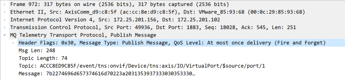
Level 1 guarantees message delivery at least once to the broker with the possibility of receiving the same message multiple times before acknowledgement.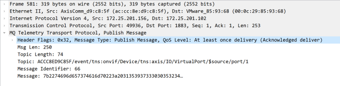
Level 2 is the highest service level providing a four-way handshake to ensure that each message is delivered exactly once to the broker.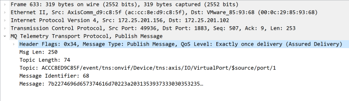
Axis topic expressions
To determine which topics are supported by an Axis device, you can use the following API calls in VAPIX or ONVIF. Although it's possible to run these commands within the SSH console from the camera, we recommend using a tool like CURL or POSTMAN instead. This approach doesn't require enabling SSH access to the device.
If you prefer to use SSH, go to Plain config > Network > SSH and log in directly to the AXIS device.
For more information about Postman and CURL, see VAPIX.
VAPIX interface
Make a GetEventInstances request to VAPIX web services as in the example below, but replace the username, password and IP address with the actual configured settings:
curl --noproxy "*" --user <username>:<password> --digest --request POST
'http://<device-address>/vapix/services' \
--header 'Content-Type: application/soap+xml;
action=http://www.axis.com/vapix/ws/event1/GetEventInstances; Charset=UTF-8' \
--data-raw '<SOAP-ENV:Envelope xmlns:SOAP-ENV="http://www.w3.org/2003/05/soap-envelope" xmlns:SOAP-ENC="http://www.w3.org/2003/05/soap-encoding"
xmlns:xsi="http://www.w3.org/2001/XMLSchema-instance"
xmlns:xsd="http://www.w3.org/2001/XMLSchema">
	<SOAP-ENV:Body>
		<m:GetEventInstances xmlns:m="http://www.axis.com/vapix/ws/event1"/>
	</SOAP-ENV:Body>
</SOAP-ENV:Envelope>'
ONVIF interface
Make a GetEventProperties request to ONVIF event services as in the example below, but replace the username, password and IP address with the actual configured settings:
curl --noproxy "*" --user <username>:<password> --digest --request POST
'http://<device-address>/onvif/services' \
--header 'Content-Type: application/xml' \
--data-raw '<?xml version="1.0" encoding="UTF-8"?>
<SOAP-ENV:Envelope
 xmlns:SOAP-ENV="http://www.w3.org/2003/05/soap-envelope"
 xmlns:wsa="http://www.w3.org/2005/08/addressing"
 xmlns:tet="http://www.onvif.org/ver10/events/wsdl">
	<SOAP-ENV:Header>
		<wsa:Action>
http://www.onvif.org/ver10/events/wsdl/EventPortType/GetEventPropertiesRequest
 </wsa:Action>
	</SOAP-ENV:Header>
	<SOAP-ENV:Body>
		<tet:GetEventProperties>
 </tet:GetEventProperties>
	</SOAP-ENV:Body>
</SOAP-ENV:Envlope>'
Output examples
onvif:Device/axis:Status/SystemReady
onvif:Device/axis:IO//.
onvif:RuleEngine/MotionRegionDetector/Motion
axis:CameraApplicationPlatform/VMD/Camera1ProfileANY
Last will testament
The last will testament settings define the behavior of the Axis device towards the MQTT server/broker after ungraceful disconnection, i.e. without the Axis device sending out a disconnect message. This could happen due to bad network connection, power disconnect, etc.
When the last will testament is enabled, the MQTT server/broker will announce the defined message in case the Axis device disconnects ungracefully. Below you will find a more detailed description of the individual settings of the last will testament and an example of a customized last will testament message.
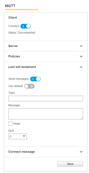
Use default: use predefined default settings.
Topic: a customized topic that will be used by the MQTT broker for disconnection announcements, i.e. to announce to subscribed MQTT clients that the Axis device has disconnected ungracefully.
Message: a customized message to be used by the MQTT broker for disconnection announcements. See below example.
Keep: also known as retain. Defines if the broker should retain the last will testament message in the broker’s cache so that new subscribers will receive the message directly after subscribing.
QoS: defines the level of service upon message delivery. Go to MQTT QoS settings for more information.
In the example below we have configured a customized last will testament (LWT) announcing the message “Axis device LWT message” in case the device disconnects ungracefully.
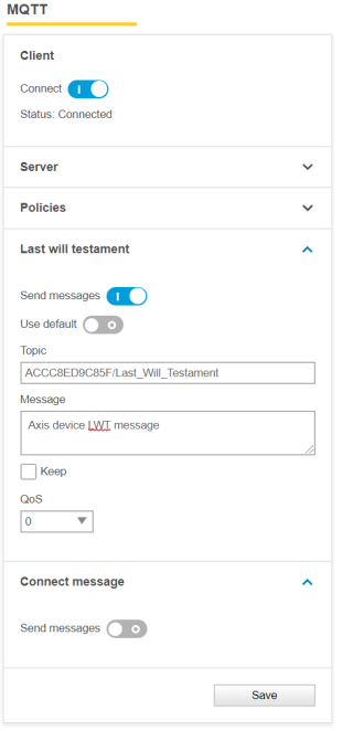 | 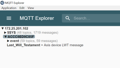 |
Connect message
The connect message can be used to let the Axis device announce its connection state to the MQTT broker and other subscribed MQTT clients. Below you will find a more detailed description of the individual settings of the connect message.
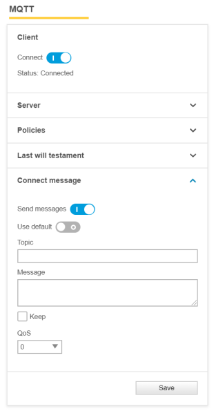
Use default: use predefined default settings.
Topic: a customized topic to be used for announcements upon connection to an MQTT broker.
Message: a customized message to be used for announcements upon connection to an MQTT broker.
Keep: also known as retain. Defines if the broker should retain the connection announcement message in the brokers cache so that new subscribers will get this message directly after subscribing.
QoS: defines the level of service upon message delivery. Go to MQTT QoS settings for more information
Configuration example with a default connect message
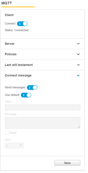 | 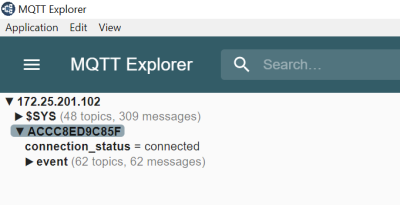 |
Configuration example with a customized connect message
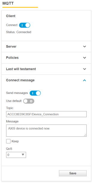 | 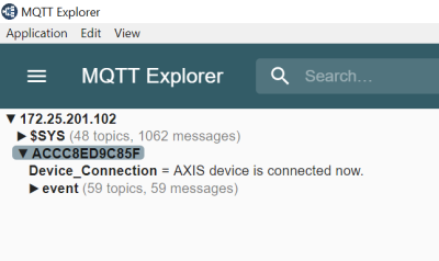 |
Generic MQTT event publishing
After connecting to an MQTT broker, the user must specify event and event filtering related configurations, which can be found under Settings > System > Events > MQTT events.
The below MQTT configuration shows a typical setup where the Axis device will be configured to send specific events to the MQTT broker, in this example by using manual trigger and virtual input.
If a specific option is missing in the list of conditions, you may need to enable the functionality and then reboot the device for the condition to appear.
Example: If "Shock detected" is missing, go to Settings > System > Detectors and enable shock detection, and then reboot the device. Performing this step will add "Shock detected" to the list of conditions.
The examples in this section are illustrated using an Eclipse Mosquitto broker and an MQTT client such as MQTT Explorer, which has a graphical user interface.
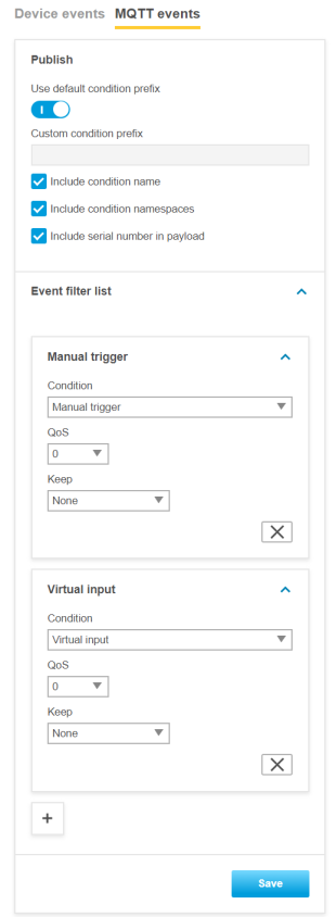
Note that if no event is added, the Axis device will not send any events to the MQTT broker. Furthermore, it’s only possible to select virtual input as an event topic. The virtual input trigger usually consists of 32–64 virtual inputs, and if virtual input is selected as an event topic, all available virtual inputs are considered.
Keep: also known as retain. Defines if the broker should retain the last state of this message in the brokers cache so that new MQTT subscribers will get the actual state of the event directly after subscription. This setting affects stateful and stateless events of an Axis device. Go to the Event and action services section in the VAPIX library for information about if particular events are stateful or stateless.
None: all events are sent as non-retained, regardless if they are stateful or stateless events.
Property: only stateful events are sent as non-retained, regardless if they are stateful or stateless events.
All: all stateful and stateless events are sent as retained messages.
QoS: defines the level of service upon message delivery. For more information, see MQTT QoS settings.
To exemplify we have configured the manual trigger as an event to be published to the MQTT broker. The manual trigger is a stateful event, meaning that the manual trigger at all times is in either one of two states; 0 or 1. In the two configurations below we compare two possible scenarios.
We do not want the broker to keep the last known event state of the manual trigger to be available for newly subscribed MQTT clients.
We do want the broker to keep the last known event state of the manual trigger to be available for newly subscribed MQTT clients.
Scenario 1 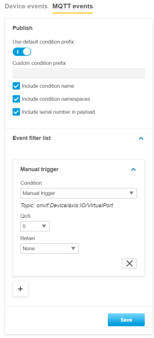 | Scenario 2 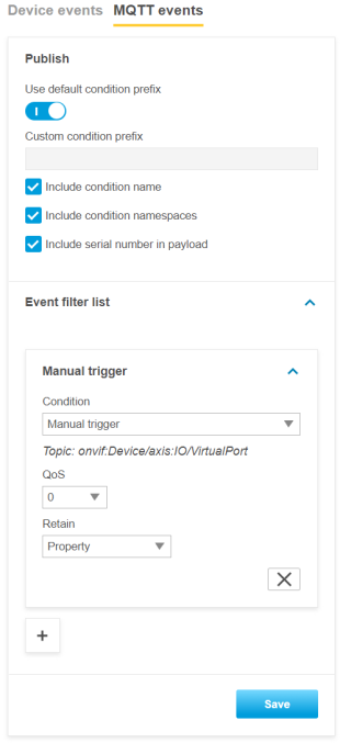 |
Let’s assume that the manual trigger was triggered, and that we have been connected to a broker in order to subscribe to it. As you can see below, we would see the actual MQTT message because we were connected and subscribed to the broker at the same time the manual trigger triggered.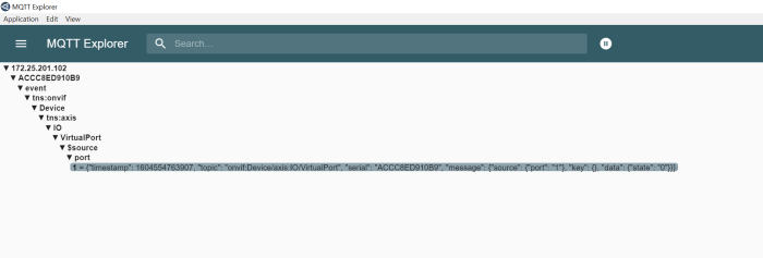
In case we would not have been connected to the broker with our MQTT client and would have connected at a later point in time, we would still see the last state of the manual trigger event if we had configured the event as "Retain=Property", as can be seen below: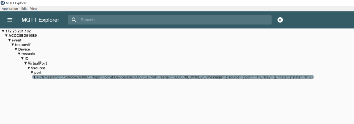
If we had configured the manual trigger event as "Retain=Off", we would not see the last message of the manual trigger and would only receive newly triggered events after we had been connected to the broker in question. Reasonably, no events would be listed:
After successful configuration we can see that the Axis device is publishing events for the manual trigger (=VirtualPort) and the 64 virtual inputs.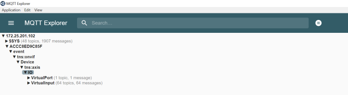
By expanding the tree structure further, we can see the status of each individual virtual input, identified by the port argument.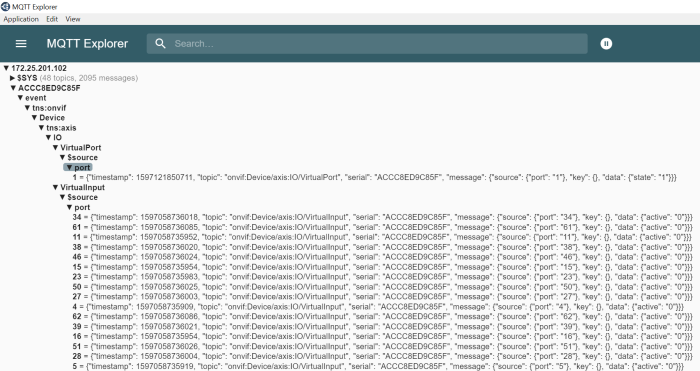
Include condition name
Enable Include condition name to include the entire event topic name tree instead of just the raw event itself.
Enabled
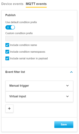 | 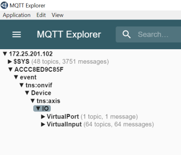 |
Disabled
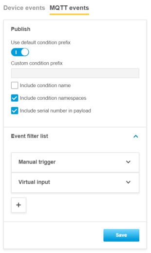 | 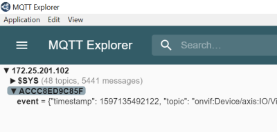 |
Include condition namespaces
Enable Include condition namespaces if the ONVIF topic namespaces should be included.
Enabled
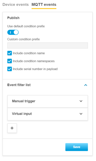 | 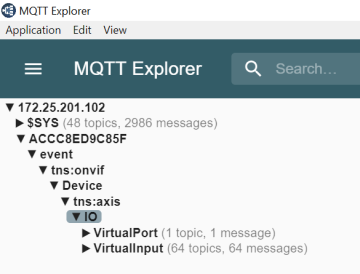 |
Disabled
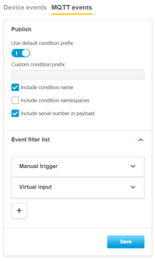 | 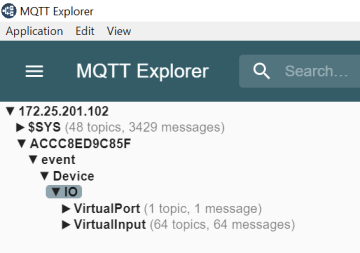 |
Include serial number in payload
Enable Include serial number in payload to include the serial number of the Axis device in the MQTT payload message. This could be used as additional information to identify the sending device.
Enabled
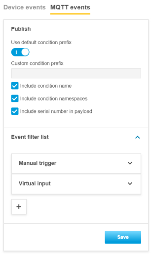 | 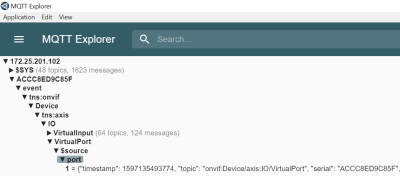 |
Disabled
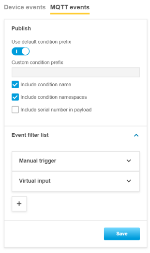 | 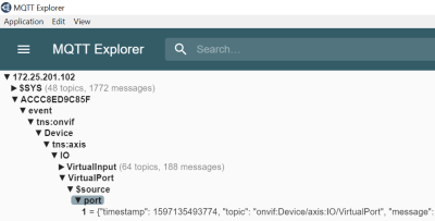 |
Custom MQTT event publishing
In addition to the generic MQTT events that come with predefined topics and payloads, the Publish MQTT action rule can be triggered by any of the available device events and send a message with a custom topic and payload.
In the below example the Axis device is publishing a message to the topic "P1375/ManualTrigger/Custom/Topics/" carrying the payload "Manual Trigger is activated". The topic can include up to 1024 characters and the payload’s limit is set to 8192 characters.
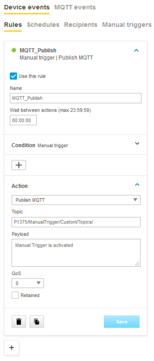 | 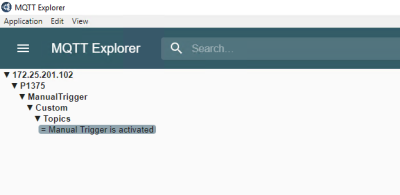 |
This video illustrates how the action rule is set up:
Custom MQTT event subscription
Custom MQTT event subscription is available from AXIS OS 10.7 and onwards and makes it possible for the Axis device to subscribe to a topic when connecting to the MQTT broker. Once subscribed, the Axis device will listen to new incoming messages and will be able to act on it, e.g. by configuration of an action rule in the built-in event system.
See how it’s configured in this video:
MQTT subscription data as overlays
With AXIS OS 11.4 and subsequent versions, you can overlay MQTT subscription data onto the video stream. In this section, we guide you through the process of implementing this feature.
First, make sure the device can successfully publish MQTT messages to the broker. In the screenshot below, we have a door monitor that can publish the door status among other information to the broker.
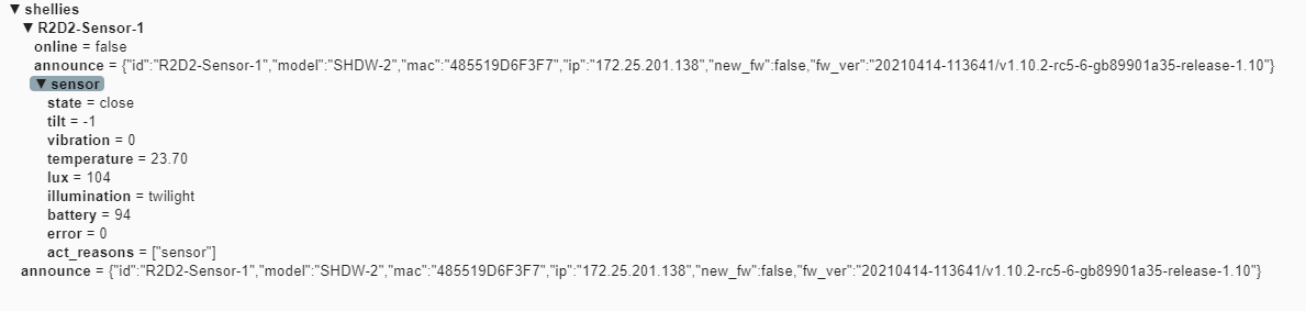
In the Axis device web interface, go to System > MQTT > MQTT client and fill in the necessary information for the MQTT broker based on your setup. Once finished, you should be able to see the MQTT connection status has changed to Connected.
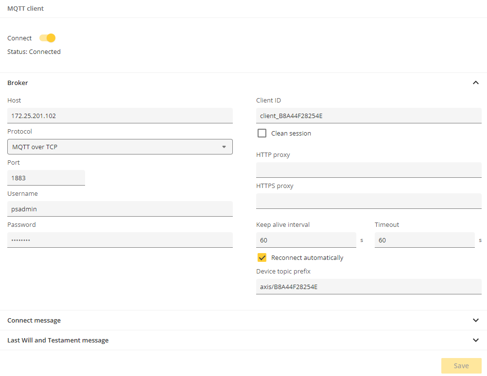
After that, you can create MQTT overlays in the Axis device. Go to System > MQTT > MQTT overlays and click Add overlay modifier.
There are two types of modifiers:
#XMP: The payload tag. The overlay modifier with #XMP form contains the entire payload of a published MQTT message.
#XMD: The data tag. The overlay modifier with #XMD form contains the JSON value of a key in the payload of a published MQTT message.
Let’s take a second look at the door monitor. In the published message, there’s a section called “announce”:

Enter shellies/announce
in the Topic filter. Click Save to subscribe to this topic and use it as an overlay.
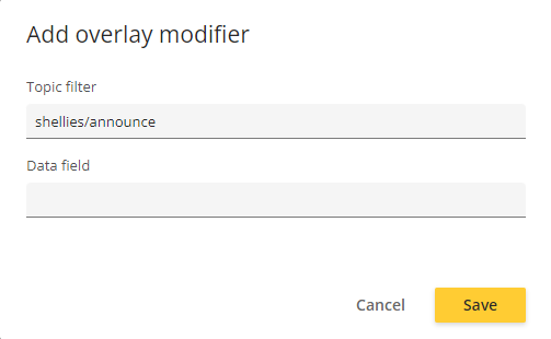
This will generate a modifier called #XMP0.
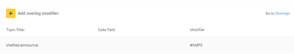
On the same page, click Overlays. On the Overlays page, you can see the entire payload of the message as an overlay in the live view.
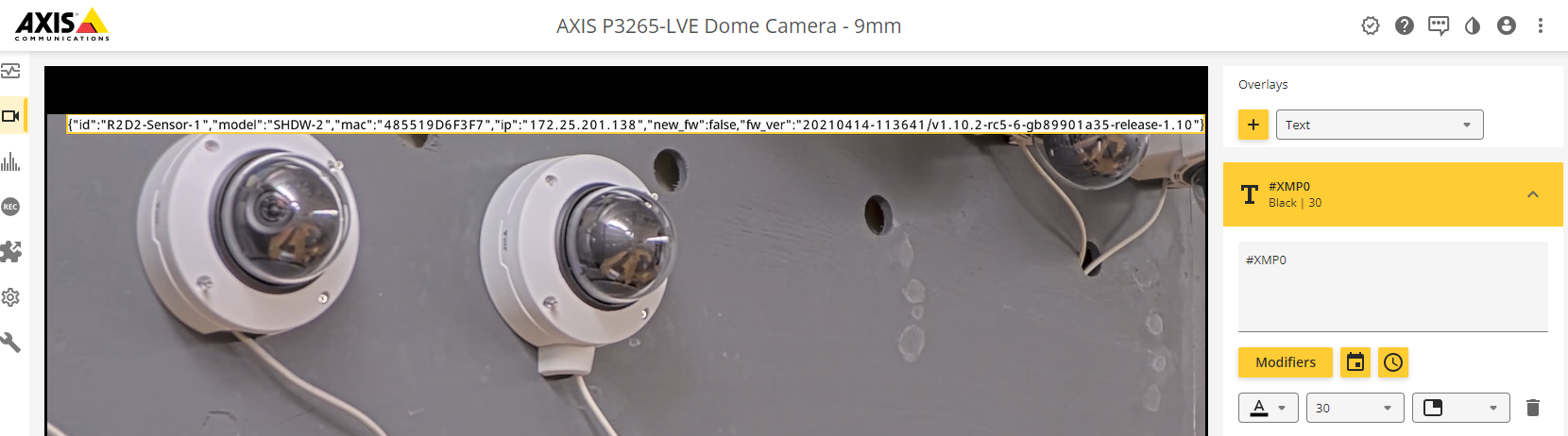
You can also choose to only overlay a specific part of the message, such as the IP address of the door monitor. That’s what the #XMD modifier is used for.
Go to System > MQTT > MQTT overlays and click Add overlay modifier. Enter shellies/announce
in the Topic filter and ip
in the Data field. Finally, click Save.
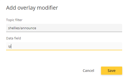
You should now see a new overlay modifier in the list:
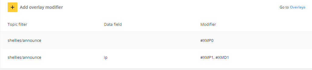
On the same page, click Overlays. On the Overlays page, create a new text overlay with #XMD1
in the string. For example, The IP address of the door monitor is: #XMD1
. In the overlay, #XMD1
will be replaced by the door monitor’s IP address.
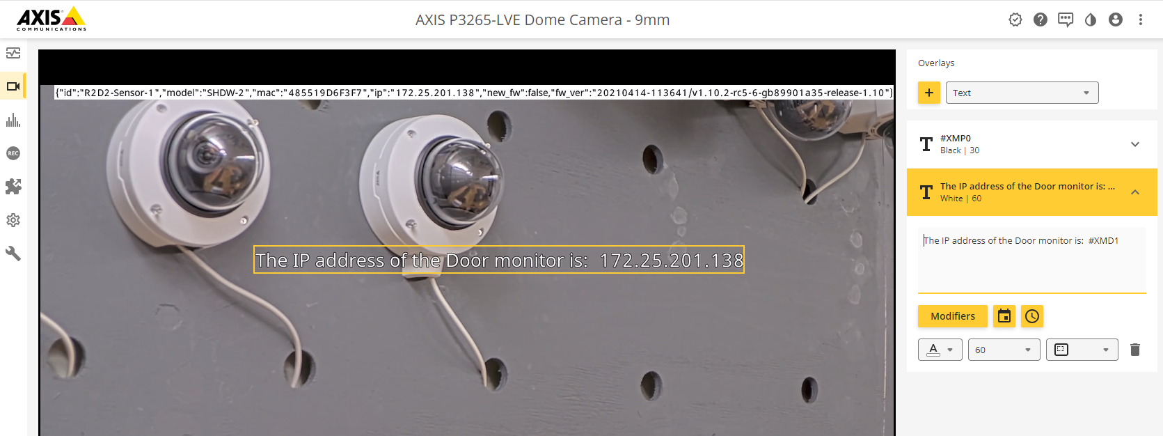
In some scenarios, subscribed messages include a lot of information in JSON format. Objects might also be nested within other objects, as in the example below.
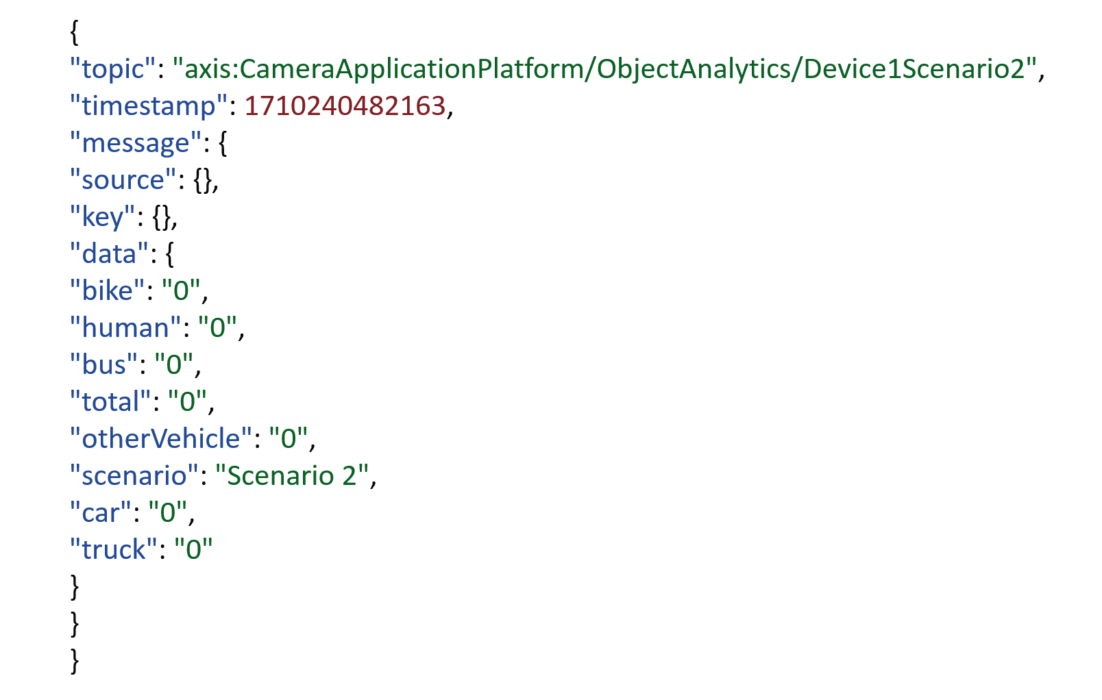
To overlay the number of humans, for instance, you would enter message.data.human
in the overlay modifier Data field.
With AXIS OS 11.8 and later, the MQTT graph overlay feature has been added to ARTPEC- 8 products as well (except the fisheye and panoramic cameras). The steps to create the MQTT overlays are the same aside from the final step to add the overlays in the video stream. Instead of overlaying the MQTT data in text format, it’s displayed in graphs.
In the following example, we’ll use the MQTT graph overlay to display the room temperature and the battery level, drawn from the door monitor data below:
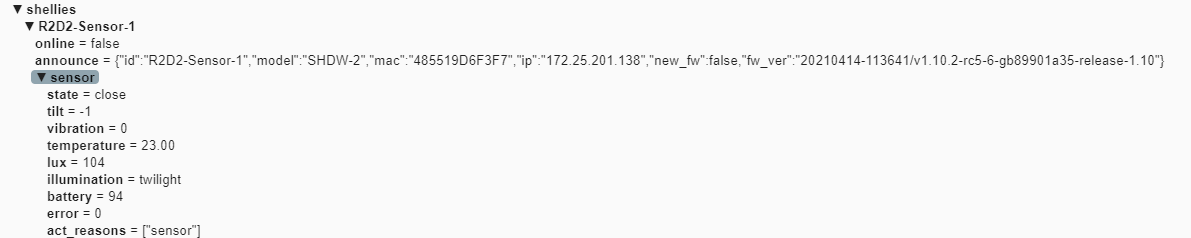
Go to System > MQTT > MQTT overlays and click Add overlay modifier . Create one for the door monitor’s room temperature and another for the door monitor’s battery level.
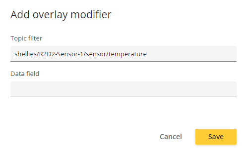
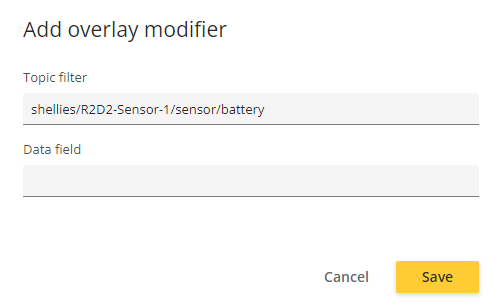
Once created, both overlay modifiers should be visible on the list.
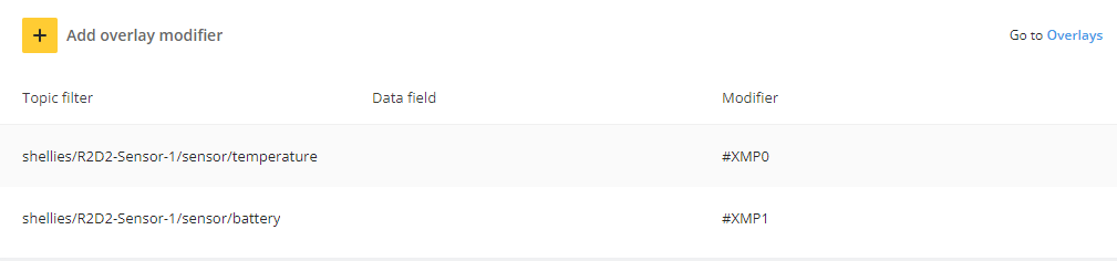
On the same page, click Overlays. On the Overlays page, create a new Widget: Linegraph overlay.
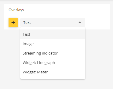
Select ##XMP0 as the overlay modifier.
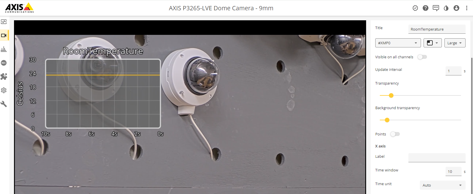
Create another graph overlay for the battery level of the door monitor. This time, use Widget: Meter instead. Select #XMP1 as the overlay modifier.
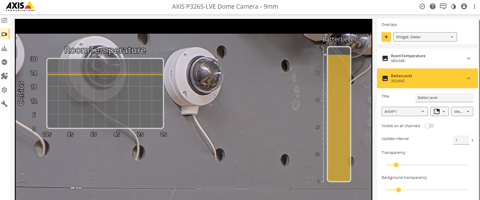
Eclipse Mosquitto
In this section you can read about the configuration steps required to connect an Axis device to an Eclipse Mosquitto MQTT broker in order to publish topics.
The below steps illustrate basic integration and use-cases within a test lab environment. Axis strongly recommends following the provider’s guidelines for an integration that maximizes the handling of certificates, tokens, user-credentials and overall cybersecurity in a production environment.
Step 1: Eclipse Mosquitto configuration
For a common Mosquitto MQTT broker configuration based on Linux Ubuntu 18.04, see this guide. The steps below cover the configuration in TCP and SSL/TLS mode only.
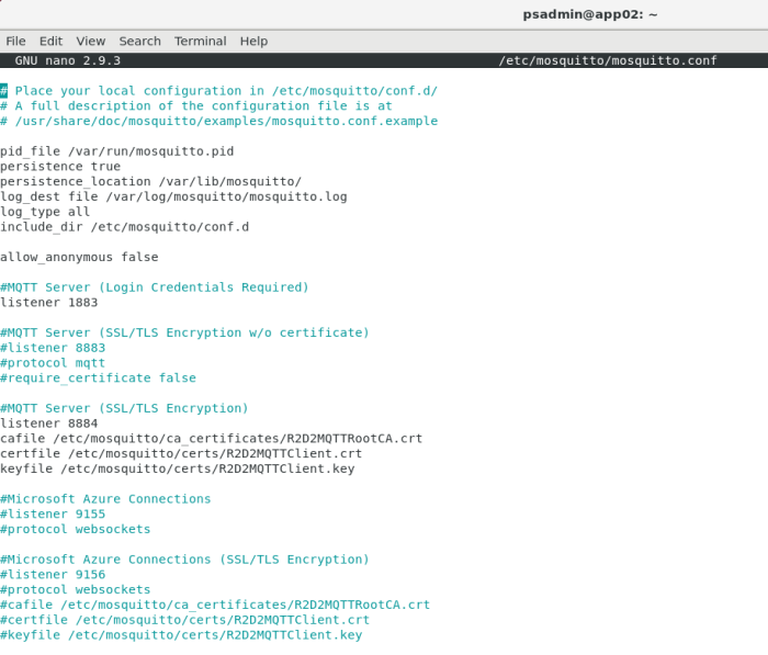
Step 2: Axis device configuration
Server configuration
MQTT over TCP 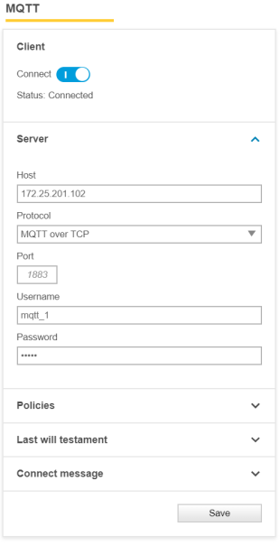 | MQTT over SSL 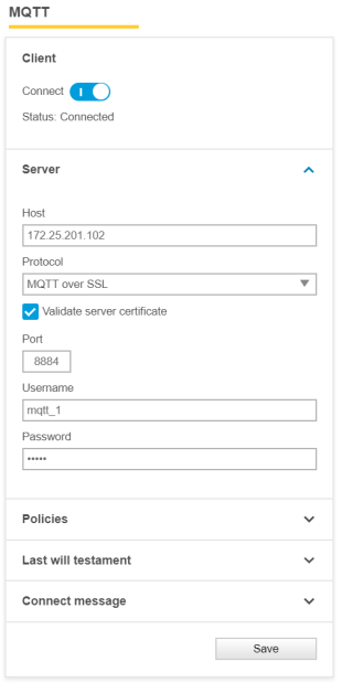 |
Policies configuration
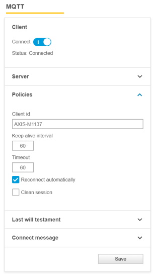
Microsoft Azure (SAS token)
In this section you can read about the configuration steps required to connect an Axis device to an MQTT broker in order to publish topics. For further reading, go to https://docs.microsoft.com/en-us/azure/iot-hub/quickstart-send-telemetry-cli and https://docs.microsoft.com/en-us/azure/iot-hub/iot-hub-mqtt-support.
The below steps illustrate basic integration and use-cases within a test lab environment. Axis strongly recommends following the provider’s guidelines for an integration that maximizes the handling of certificates, tokens, user-credentials and overall cybersecurity in a production environment.
Step 1: Create an IoT device
In order to get started, an IoT device must be created in Microsoft Azure. Follow the steps below in order to proceed.

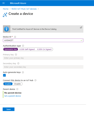
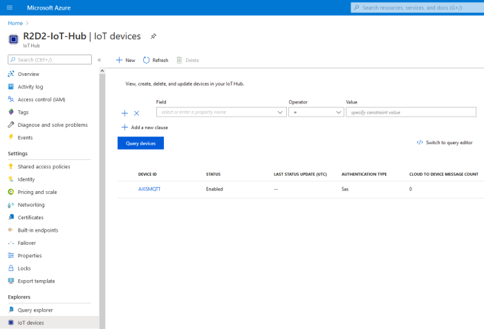
After creating a device, obtain the hostname of your Microsoft Azure entity. This can be looked up in the hub overview.
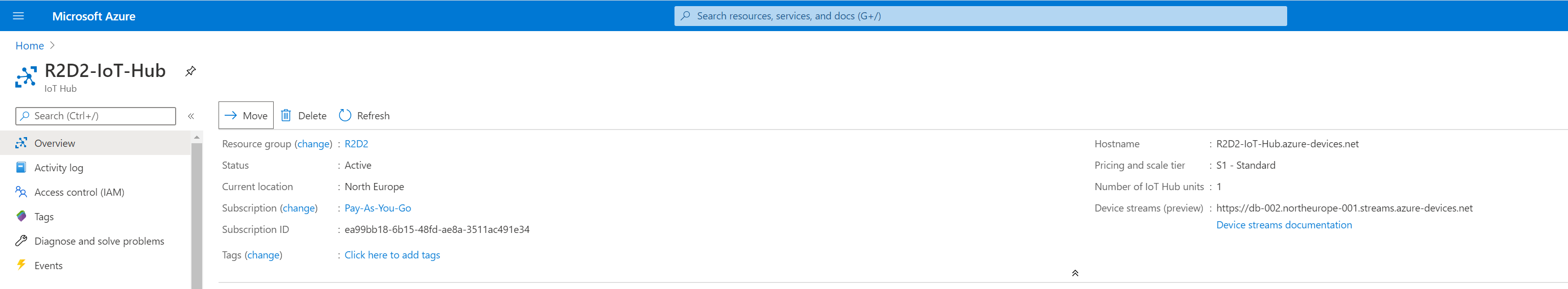
Step 2: Generate SAS token
The SAS token can be generated using the Cloud Shell console in Microsoft Azure. In the following example, the password is generated and valid for 3600 seconds. This SAS token is used later on to connect the Axis device to the Microsoft Azure MQTT broker.
Cloud Shell command: az iot hub generate-sas-token -d AXISMQTT -n R2D2-IoT-Hub --du 3600
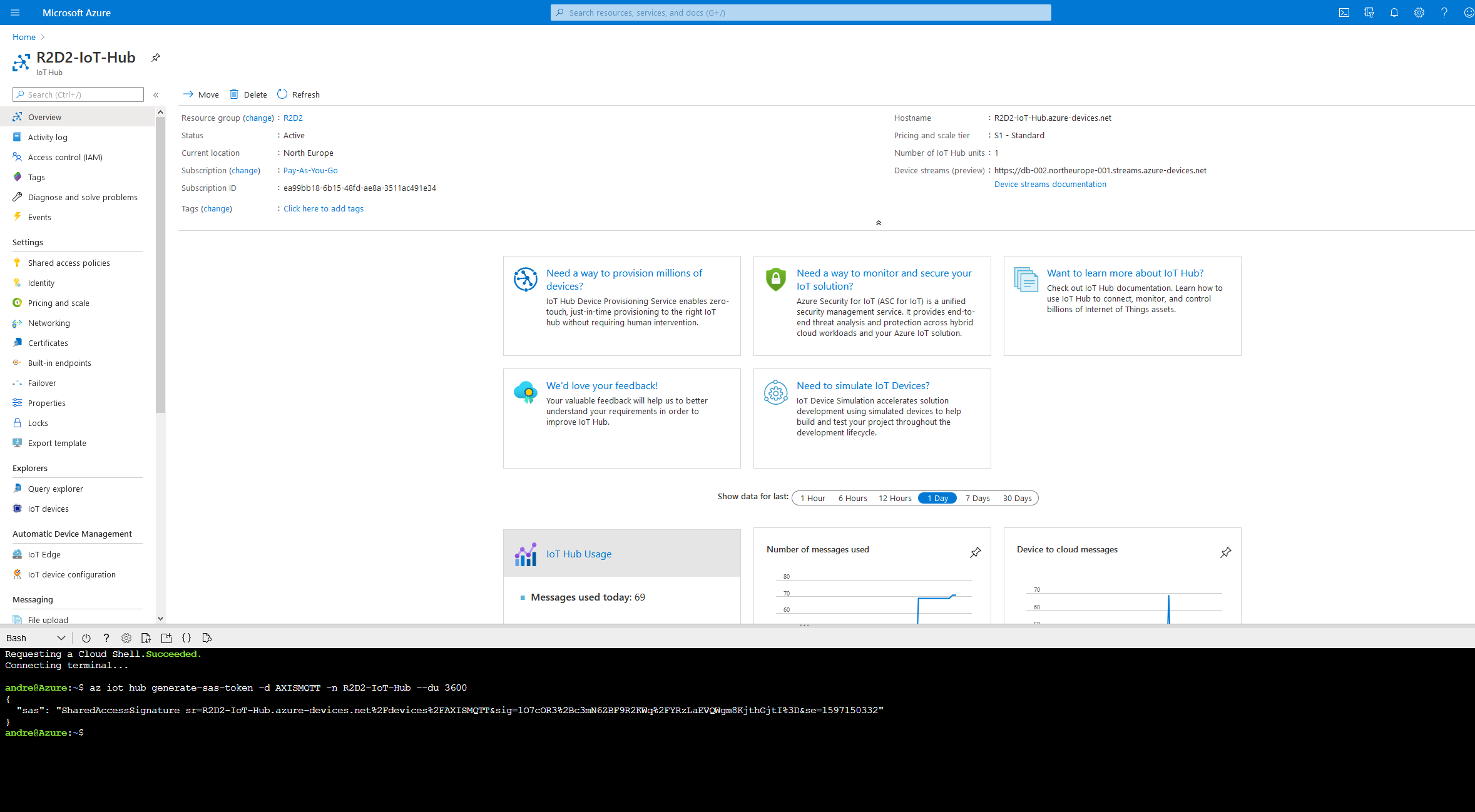
Step 3: Axis device configuration
With the information provided in Step 1 and Step 2 we can now connect the Axis device to the Microsoft Azure MQTT broker.
Note that the custom condition prefix, disabling the condition name and the custom basepath is mandatory for the Axis device to publish messages.
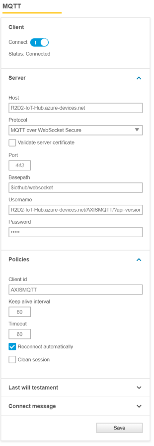 | 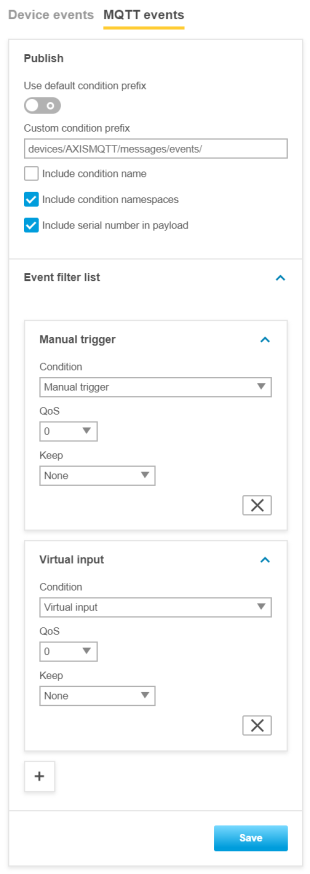 |
Step 4: Listen to MQTT events
Now we’re ready to test our setup. Use the following command in Cloud Shell to listen to incoming MQTT events from the Axis device. The simplest way of testing is to use manual trigger in the Axis device.
Cloud Shell Command: az iot hub monitor-events --hub-name R2D2-IoT-Hub
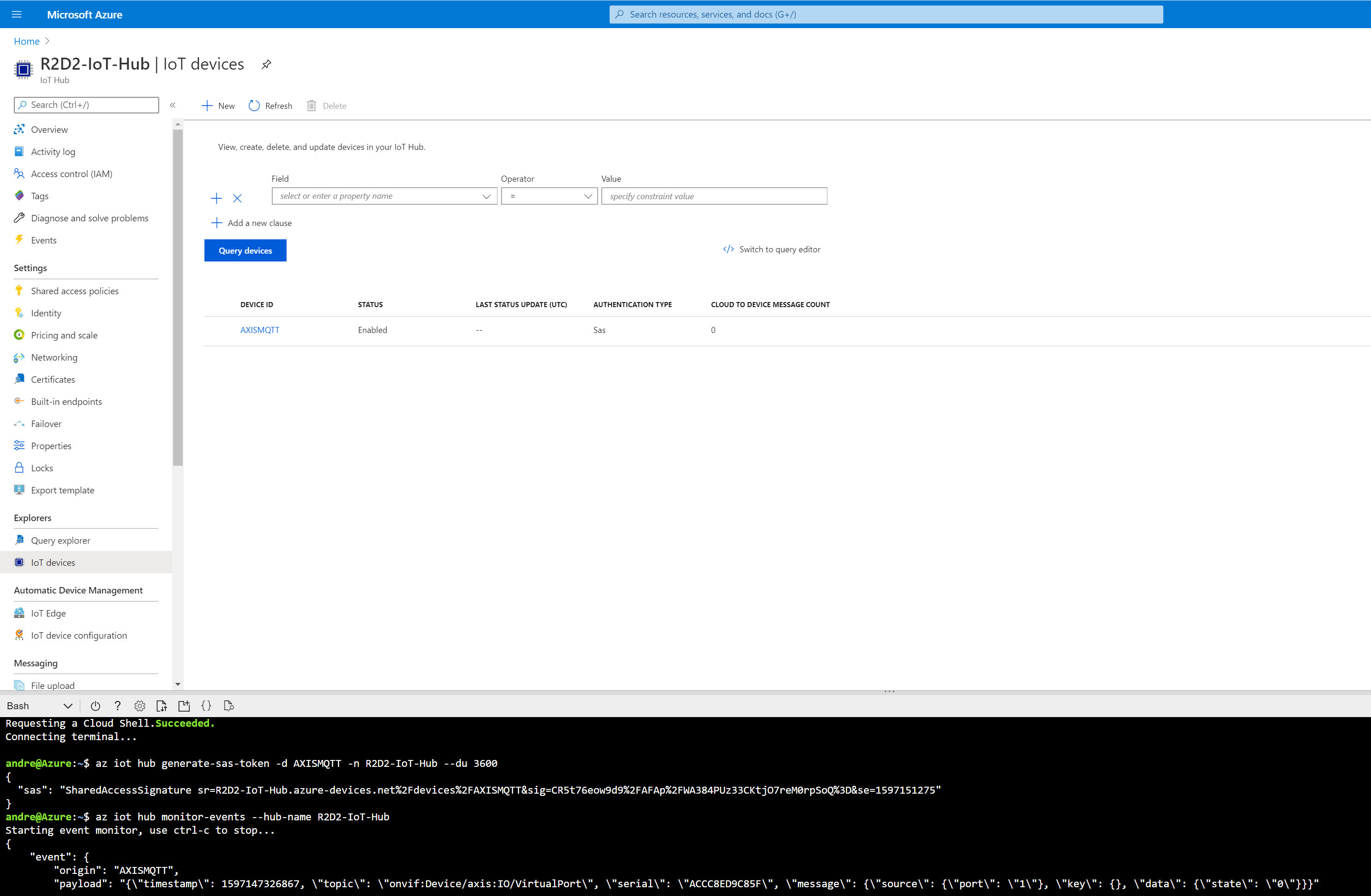
Microsoft Azure (certificate authentication)
In this section you can read about the configuration steps required to connect an Axis device to an MQTT broker in order to publish topics. For further reading, go to https://docs.microsoft.com/en-us/azure/iot-hub/quickstart-send-telemetry-cli and https://docs.microsoft.com/en-us/azure/iot-hub/iot-hub-mqtt-support.
The below steps illustrate basic integration and use-cases within a test lab environment. Axis strongly recommends following the provider’s guidelines for an integration that maximizes the handling of certificates, tokens, user-credentials and overall cybersecurity in a production environment.
Step 1: Certificate authority configuration
In order to configure certificate-based authentication in Microsoft Azure, a trusted root certificate is required, which is used to sign and verify clients and their certificates in return. The below process describes how to add a root certificate in Azure and how to apply the proof-of-possession method in order to prove to Azure that this root certificate should be verified and trusted.
Let’s create a root certificate of our choice by running the following commands:openssl genrsa -des3 -out R2D2AzureRootCA.key 2048
openssl req -new -x509 -days 36500 -key R2D2AzureRootCA.key -out R2D2AzureRootCA.pem
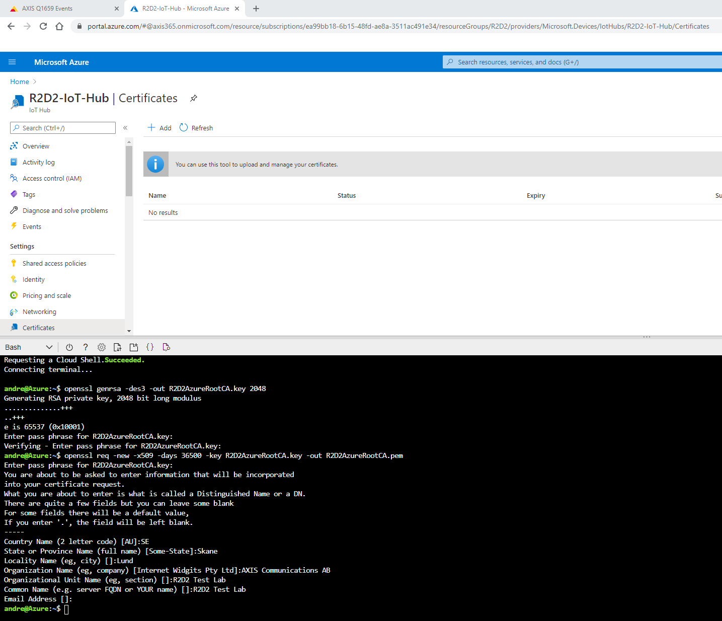
Download the certificate that was created in the PowerShell and upload the certificate in the certificate store as seen below.
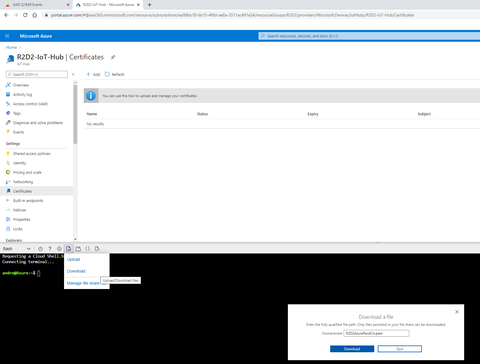
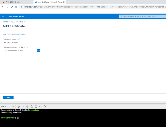
As you might have noticed, the status of the new root certificate is “Unverified”, meaning that we need to prove to Azure that the uploading user is in real possession of the certificate and its authority. Therefore, Azure requires us to sign a new certificate from the root certificate that was uploaded, which includes the below verification code in the CN/Subject of the new certificate.
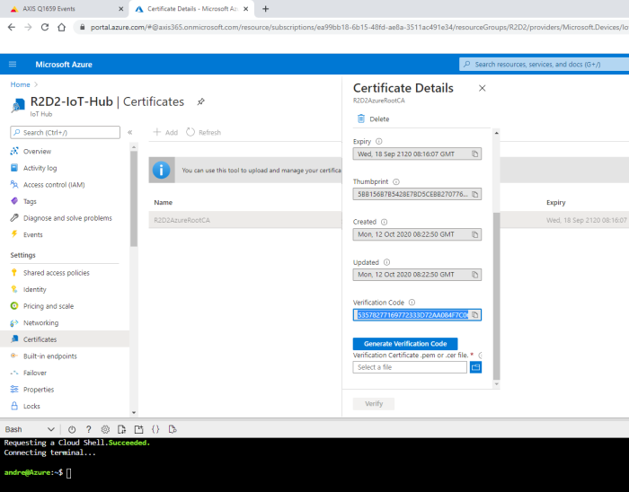
With the help of the below commands, a new certificate is created. Observe that the verification code must be used in the CN/Subject of the new certificate. Note that a challenge password during the certificate creation is not needed.
openssl genrsa -out R2D2AzureRootCAProof.key 2048
openssl req -new -out R2D2AzureRootCAProof.csr -key R2D2AzureRootCAProof.key
openssl x509 -req -in R2D2AzureRootCAProof.csr -CA R2D2AzureRootCA.pem -CAkey R2D2AzureRootCA.key -CAcreateserial -out R2D2AzureRootCAProof.pem -days 36500
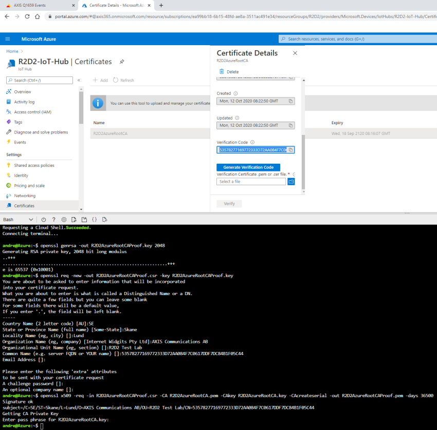
After the certificate has been successfully created, download it in order to upload it into the certification store to confirm the proof-of-possession. Upon successful verification, the certificate status should change to “Verified”.
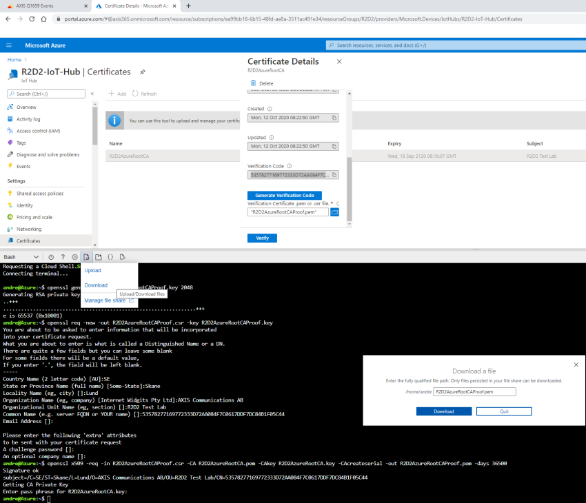
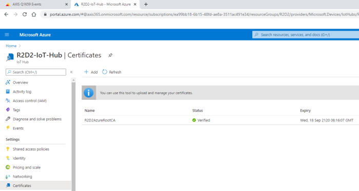
Step 2: Create an IoT device
In order to send MQTT messages from an Axis device to Microsoft Azure using certificate-based authentication, a new IoT device needs to be created with the appropriate authentication method.
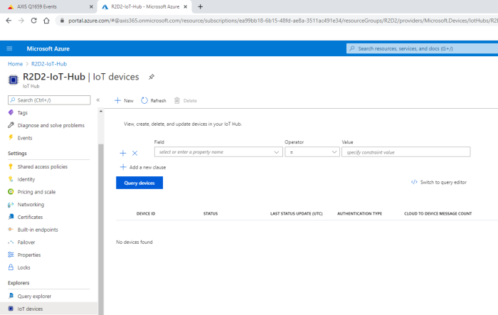
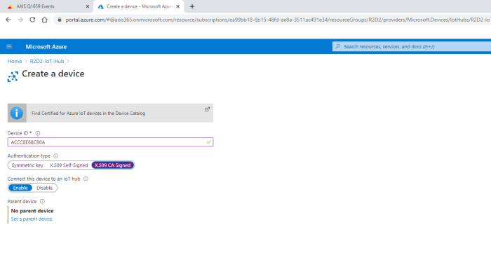
The Axis device must authenticate using a new client certificate that needs to be generated and signed from the root certificate that we uploaded in step 1. The below commands or similar are needed to do so:
openssl genrsa -out R2D2AzureACCC8E68CB0A.key 2048
openssl req -new -out R2D2AzureACCC8E68CB0A.csr -key R2D2AzureACCC8E68CB0A.key
openssl x509 -req -in R2D2AzureACCC8E68CB0A.csr -CA R2D2AzureRootCA.pem -CAkey R2D2AzureRootCA.key -CAcreateserial -out R2D2AzureACCC8E68CB0A.pem -days 36500
Observe that the device ID must match the CN/Subject of the client certificate exactly, or the authentication will fail. Note that a challenge password during certificate creation is not needed.
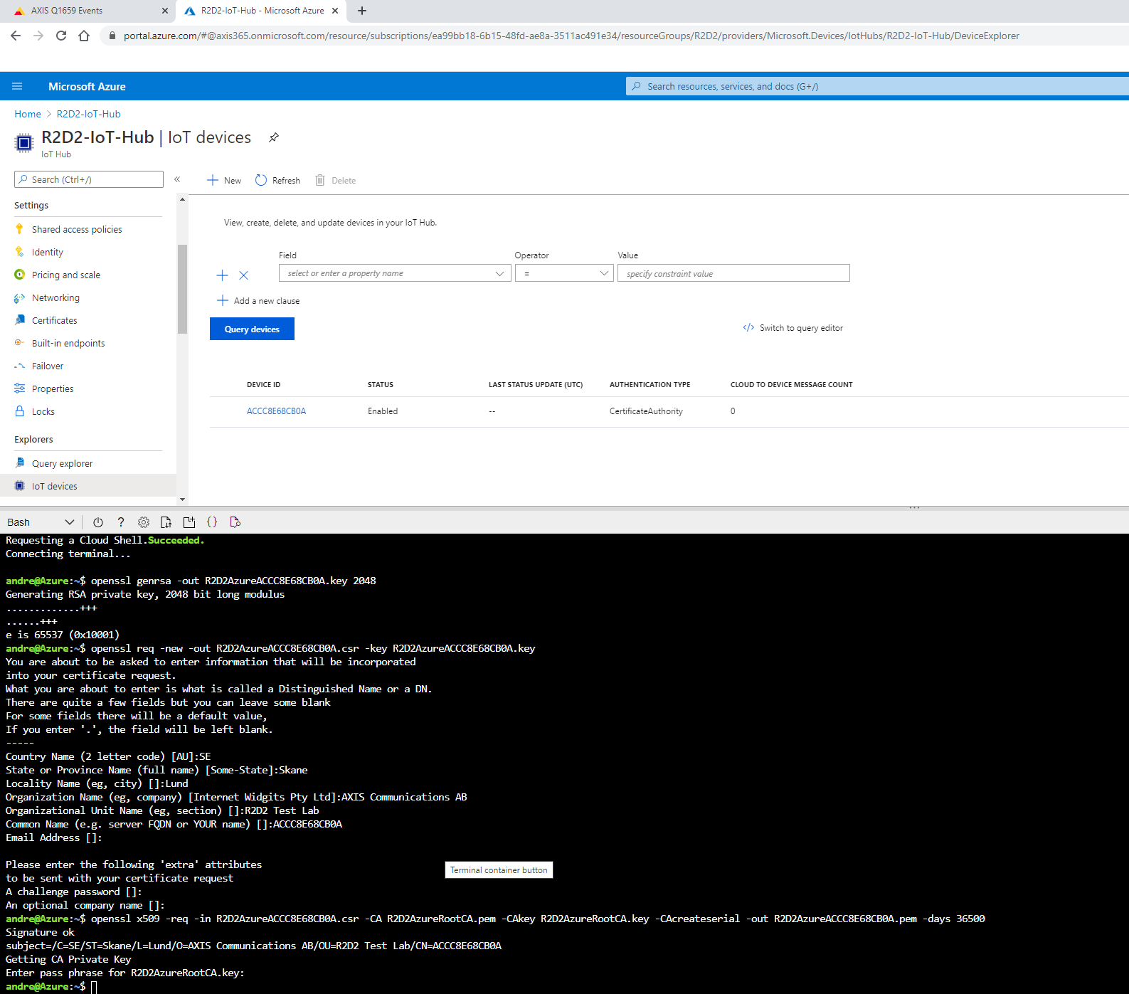
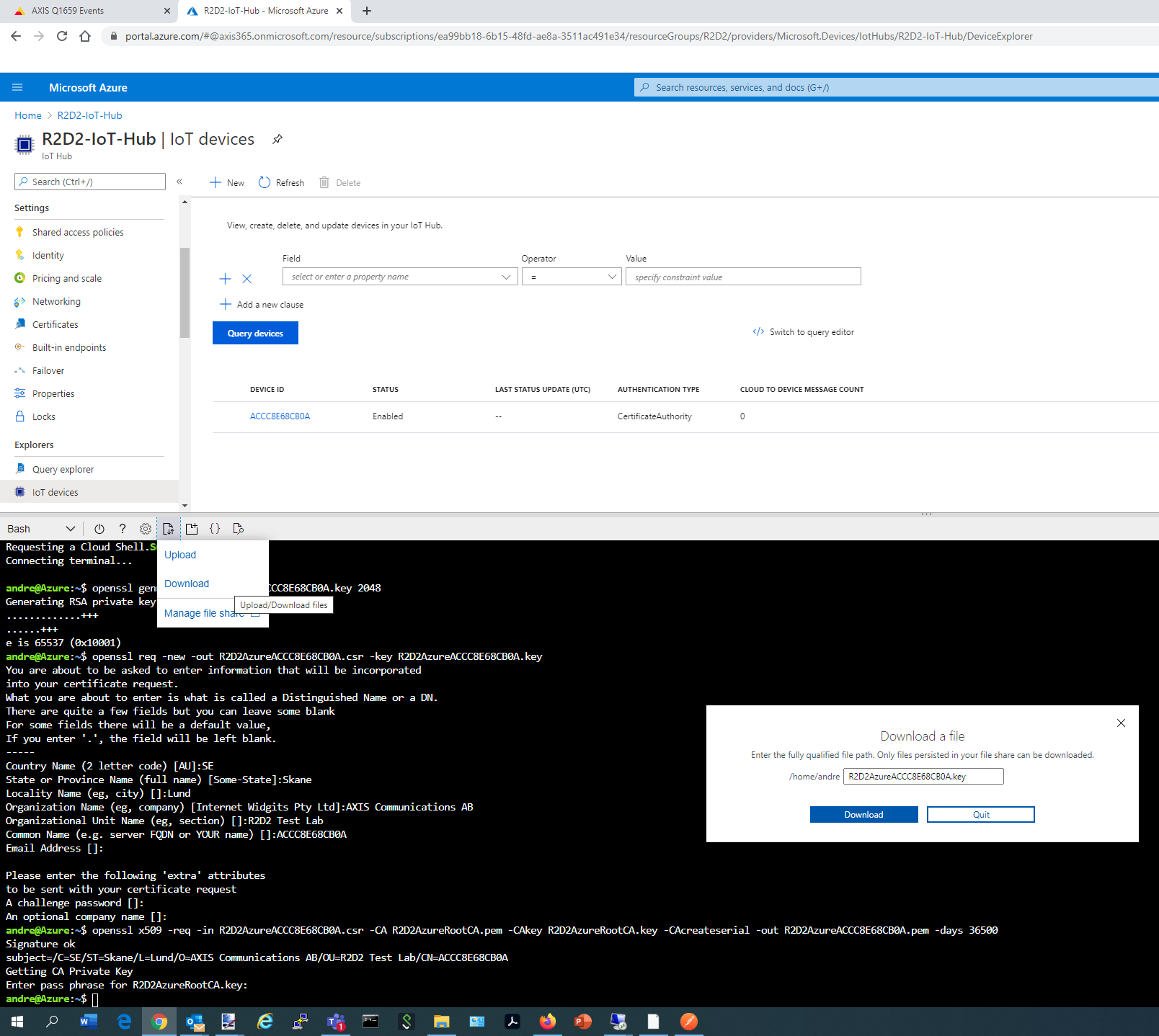
Step 3: Axis device configuration
In the last step, the previously created client certificate needs to be uploaded onto the Axis device, and be selected in the MQTT broker configuration. The rest of the configuration is well documented in the Microsoft Azure guidelines.
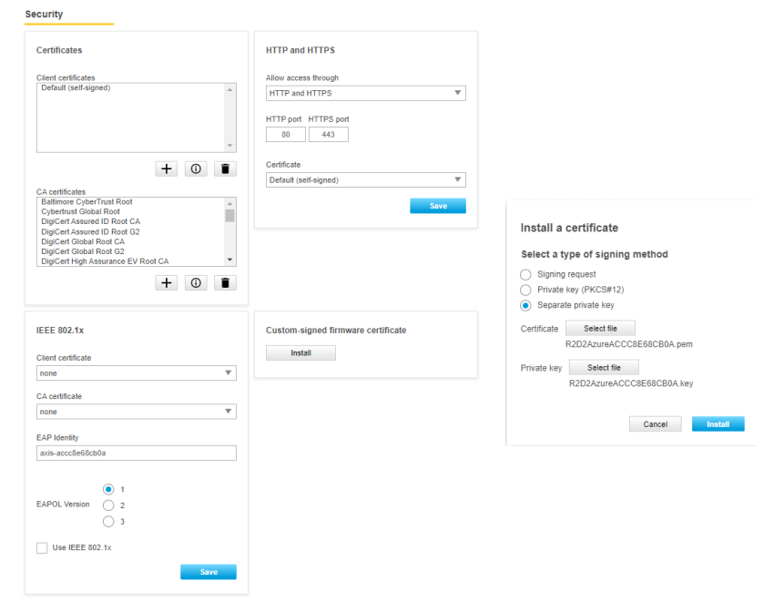
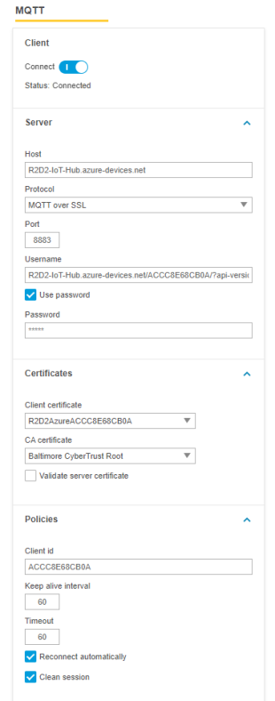 | 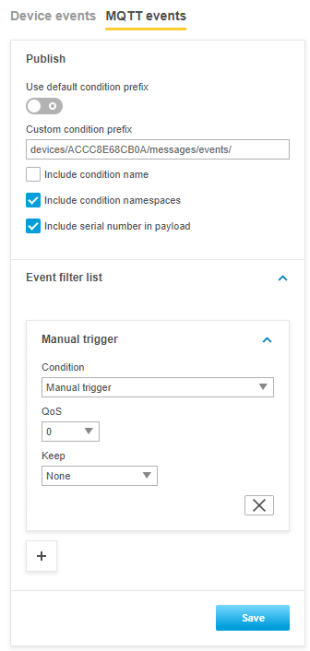 |
Step 4: Listen to MQTT events
Now we're ready to test our setup. Use the following command in the Cloud Shell to listen to incoming MQTT events from the Axis device. The simplest way of testing is to use the manual trigger in the Axis device.
Cloud Shell command: az iot hub monitor-events --hub-name R2D2-IoT-Hub
Go to Microsoft Azure (SAS token) and see the example in Step 4 for more information.
Amazon Web Services (AWS)
In this section you can read about the configuration steps required to connect an Axis device to an Amazon Web Services (AWS) MQTT broker in order to publish topics. For further reading, go to https://docs.aws.amazon.com/iot/latest/developerguide/mqtt.html#mqtt-sdk.
The below steps illustrate basic integration and use-cases within a test lab environment. Axis strongly recommends following the provider’s guidelines for an integration that maximizes the handling of certificates, tokens, user-credentials and overall cybersecurity in a production environment.
Step 1: Create a thing policy
Before we start creating a thing device in AWS, we want to configure the thing policy first. The thing policy is basically access and connection rights given to a device upon creation. The below example illustrates a policy that lets the Axis device connect and publish messages.
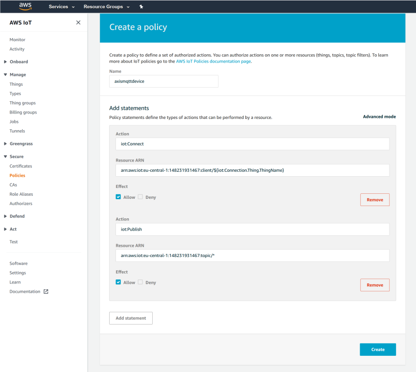
Step 2: Create IoT device (thing)
After creating the thing policy, it is time to create the actual device. AWS IoT Core is providing access via certificate-based authority rather than credential-based authentication. So, a certificate and a private key are generated during the process of creating a thing as well.
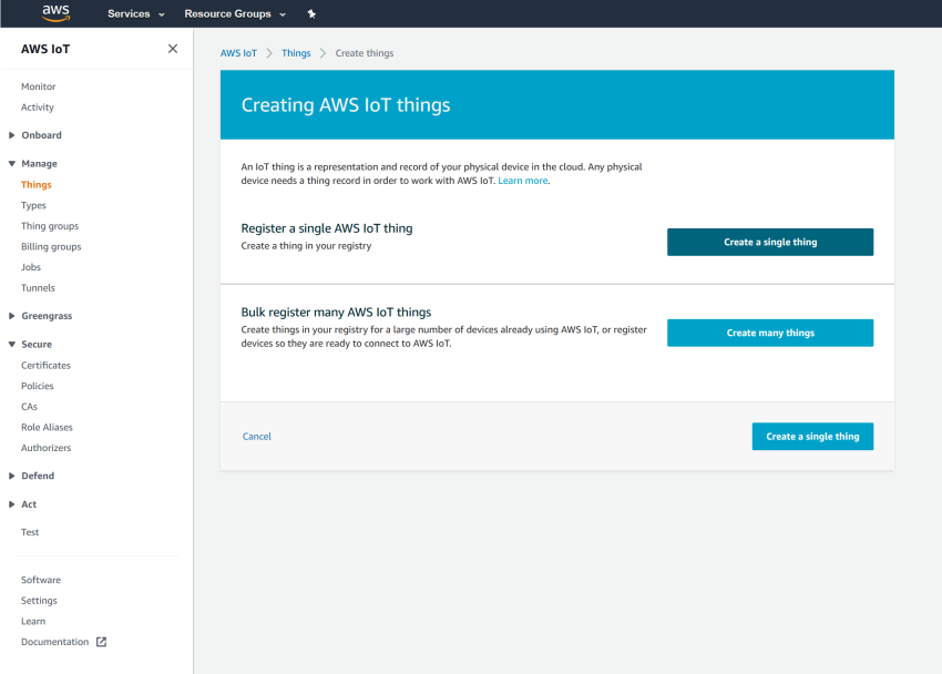
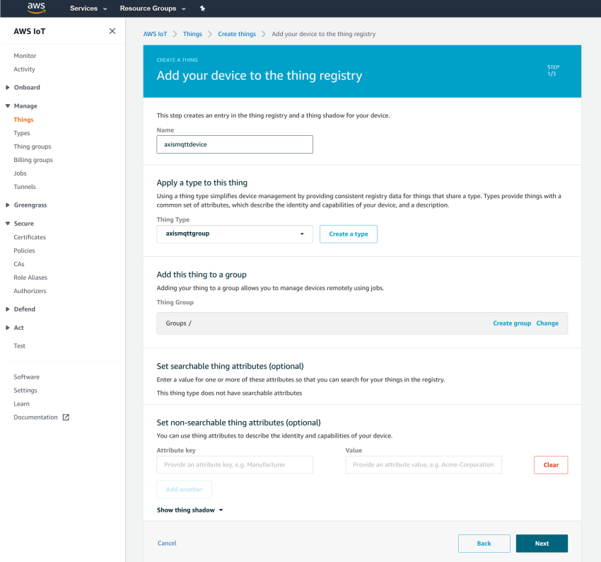
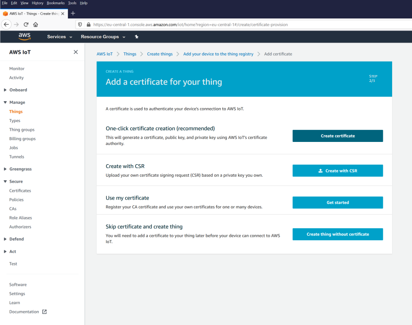
Observe that the certificate and private key must be uploaded to the Axis device. If the Axis device should validate the AWS MQTT broker as well, the Amazon Root CA must be uploaded on the Axis device too. Furthermore, make sure that the certificates are activated by toggling the button as illustrated in the screenshot.
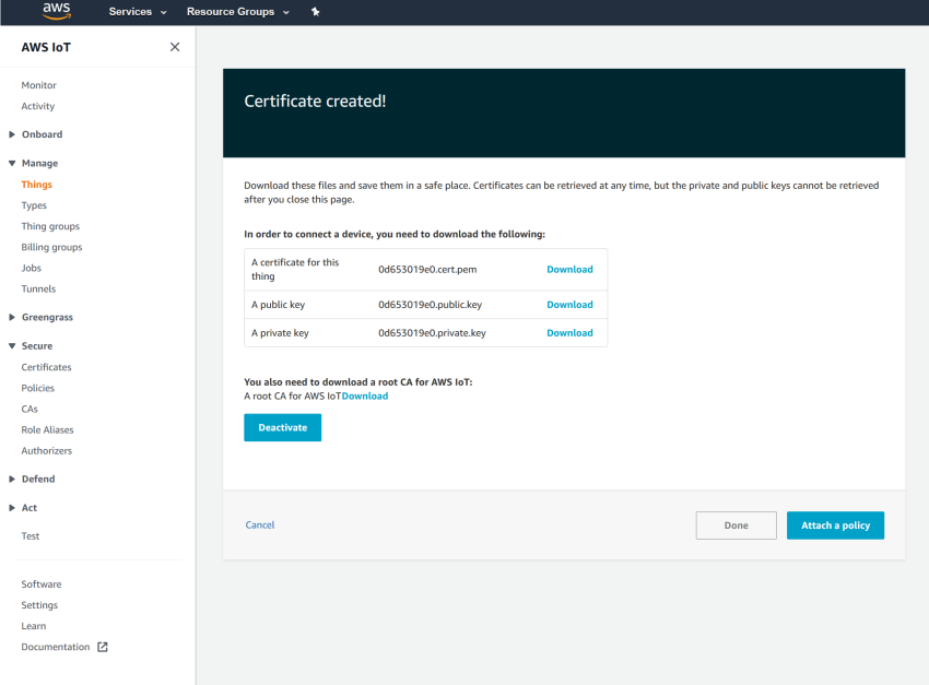
Here we attached the policy that we created in Step 1 to the thing device we are creating. After doing this, the thing is ready and it is time to configure the Axis device.
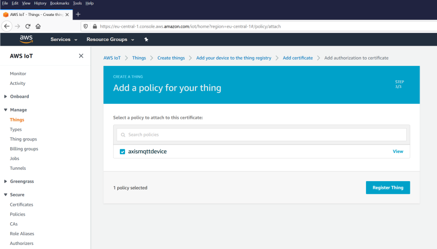
Step 3: Axis device configuration
With the information provided in step 1 and step 2 we can now connect the Axis device to the AWS MQTT broker.
Note that AWS IoT Core enforces a hard limit on the length of the topic expression so we simply started with only including the condition name to keep the topic short.
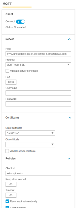 | 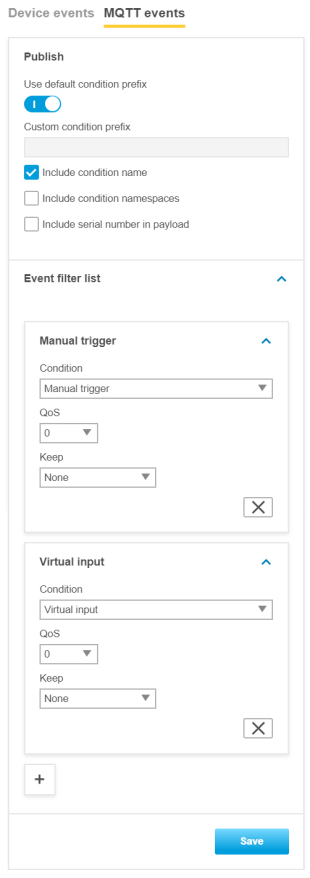 |
Step 4: Listen to MQTT events
Now we are ready to test our setup. With the help of Amazon CloudWatch we can verify if the Axis device can send MQTT messages to the AWS cloud successfully.
First, make sure you have logging enabled. This will then result in the AWS cloud logging connection attempts.
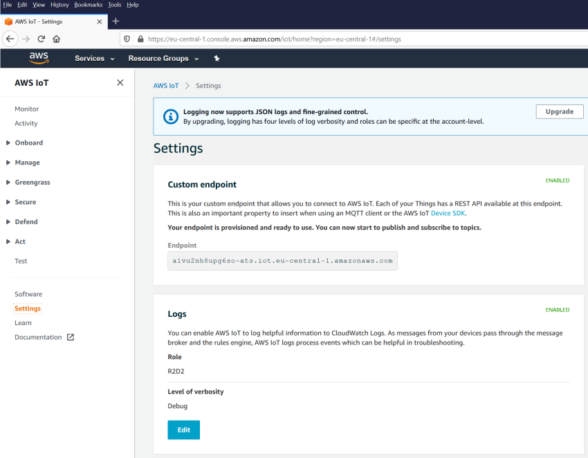
By using the Amazon CloudWatch service, the AWSIoTlogs log group will reveal connection attempts and whether or not MQTT actions such as publishing or subscribing were successful.
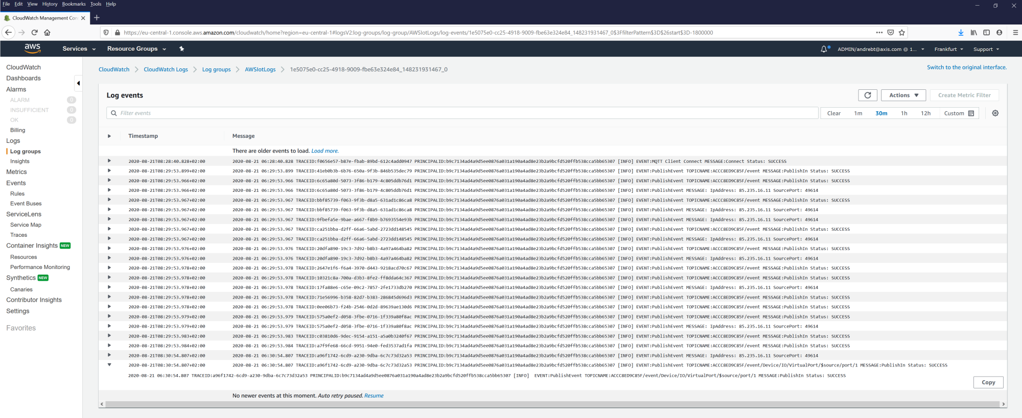
IBM Watson
In this section you can read about the configuration steps required to connect an Axis device to an IBM Watson MQTT broker in order to publish topics. For further reading, go to https://developer.ibm.com/articles/iot-mqtt-why-good-for-iot/.
The below steps illustrate basic integration and use-cases within a test lab environment. Axis strongly recommends following the provider’s guidelines for an integration that maximizes the handling of certificates, tokens, user-credentials and overall cybersecurity in a production environment.
Step 1: Create IoT device
Follow the steps below to create an IoT device.
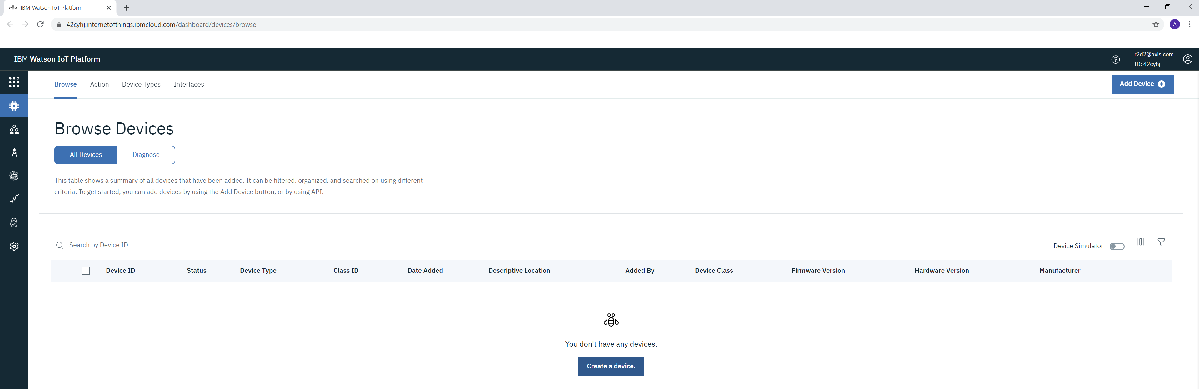
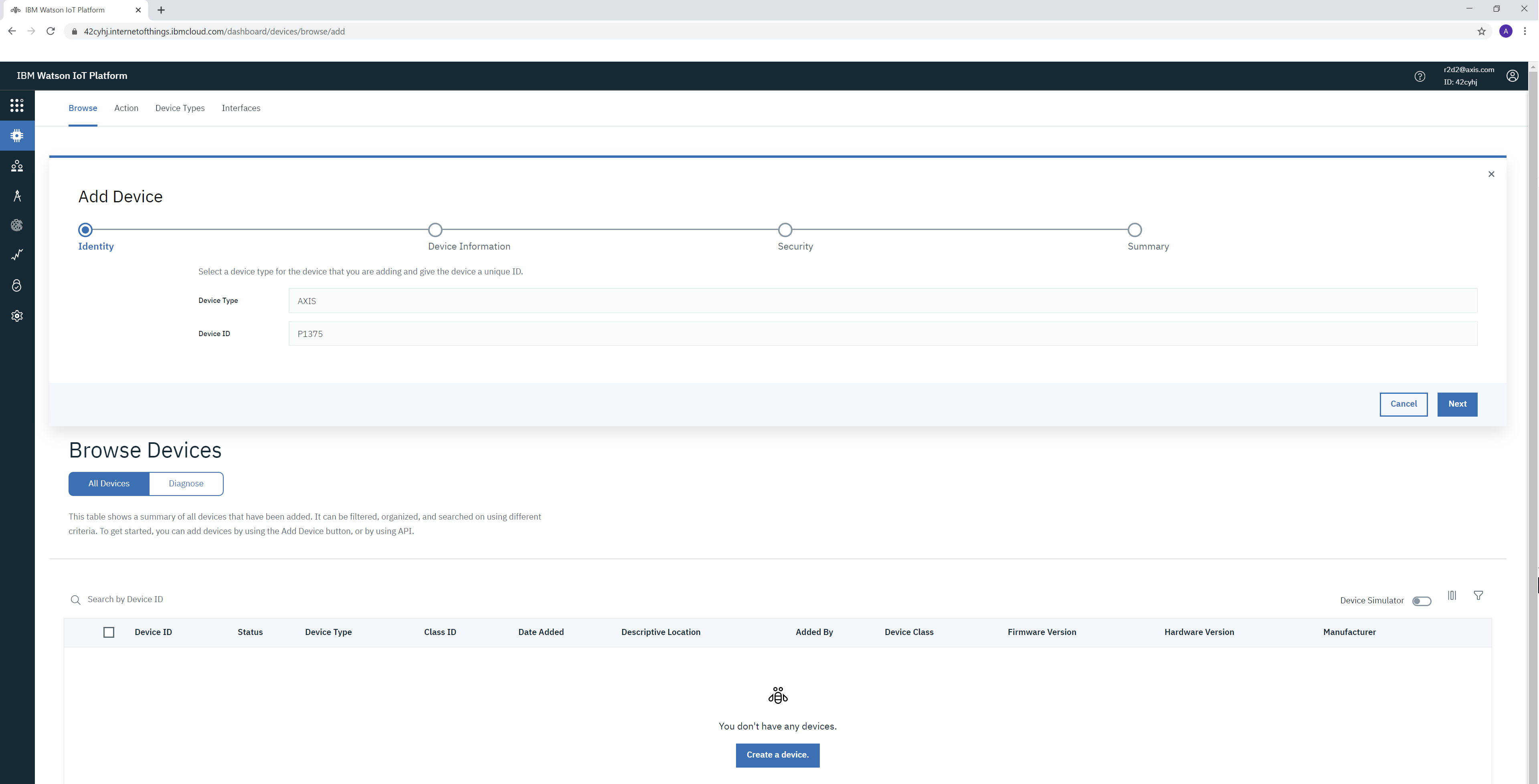
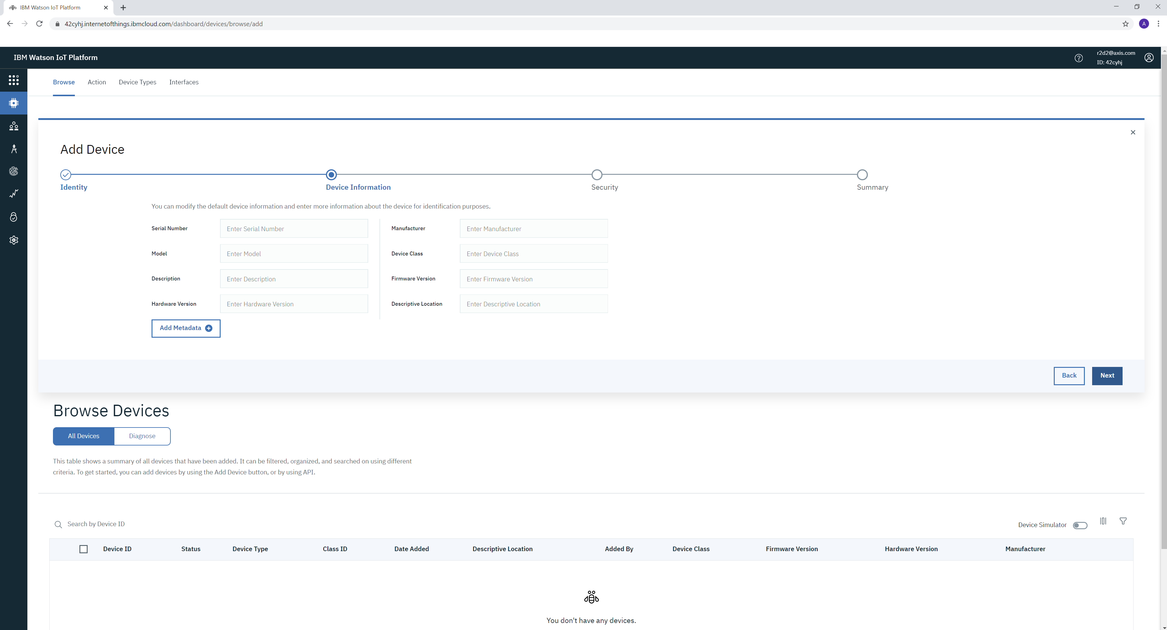
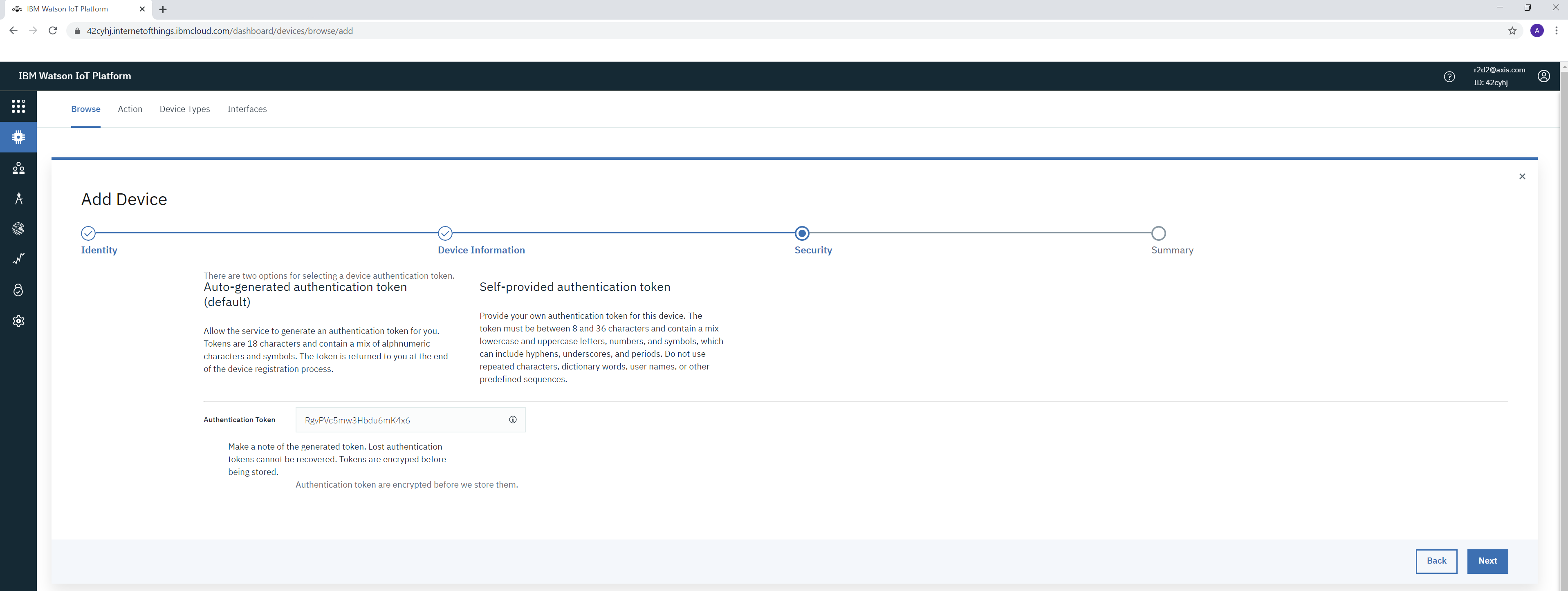
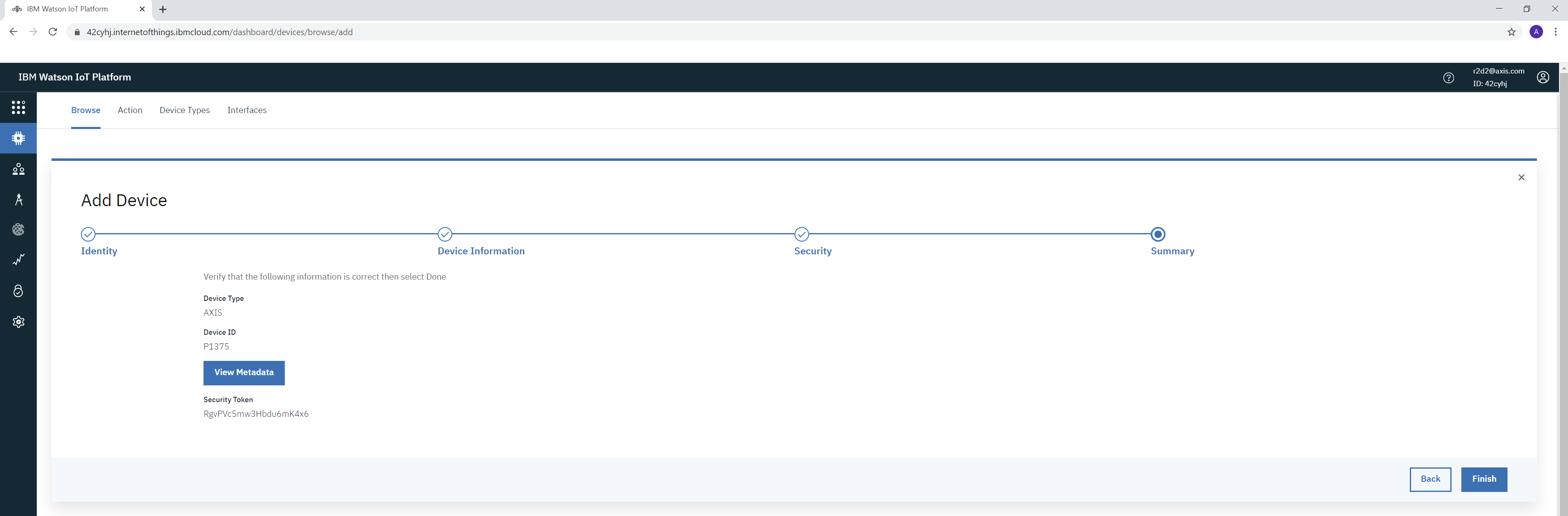
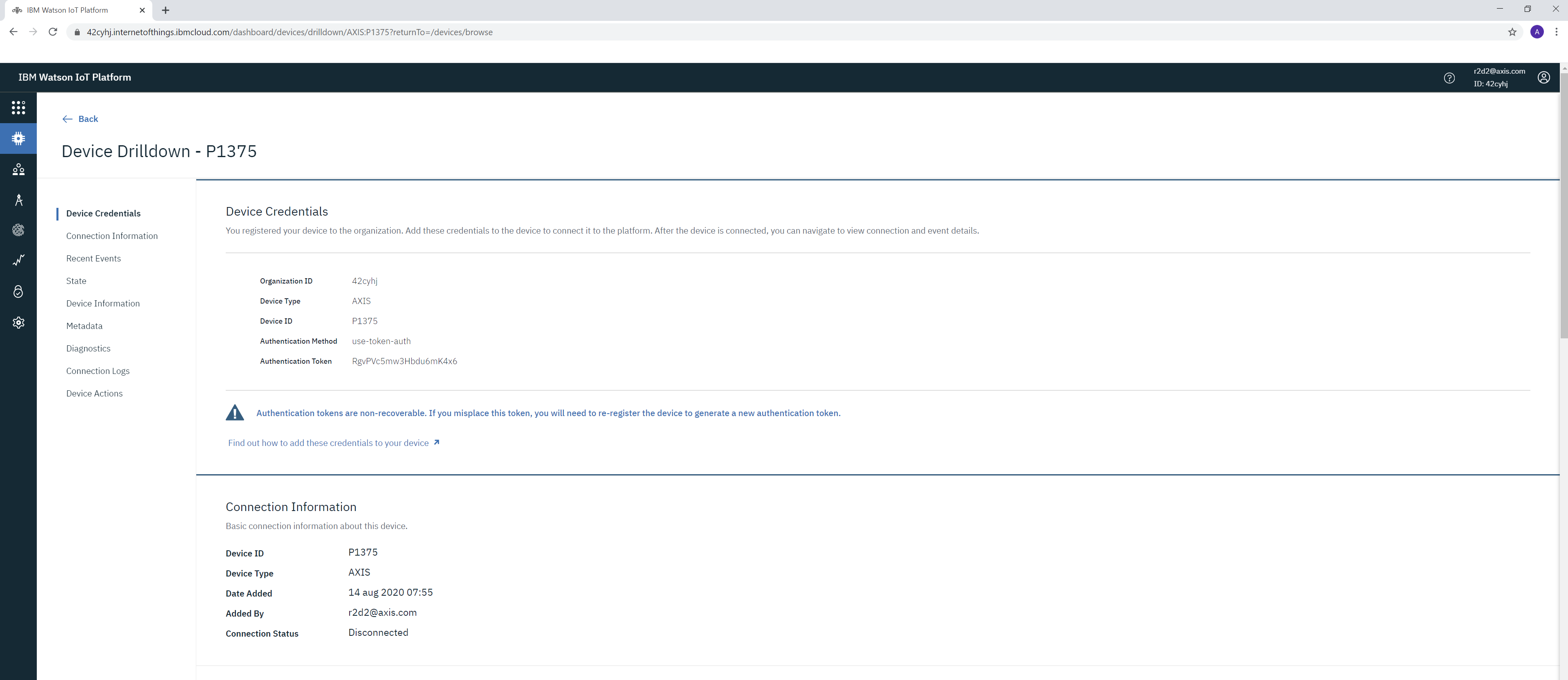
Step 2: Axis device configuration
With the information and settings provided by the IoT device creation in Step 1, we can now connect the Axis device to the IBM MQTT broker. Again, below is a typical example.
Note that the custom condition prefix in the MQTT events and the disabling of the condition name are mandatory for the Axis device to publish messages.
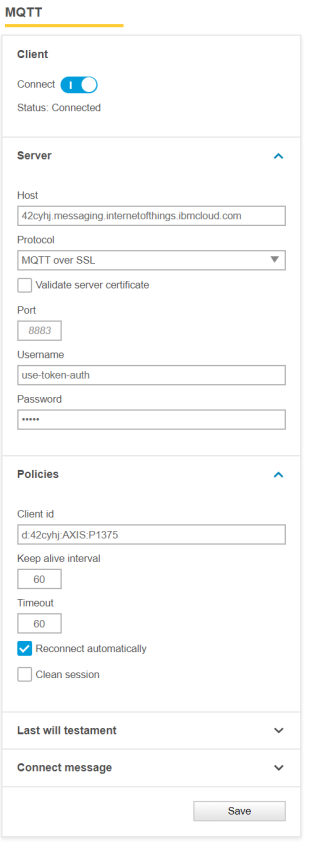 | 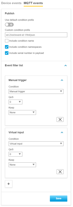 |
Step 3: Listen to MQTT events
IBM Watson Cloud does not possess a built-in MQTT client for subscribing to events in the cloud. We therefore use MQTT Explorer. In order for MQTT Explorer to connect to the IBM MQTT broker, it is necessary to first generate API keys to allow access. This is described in the following images.
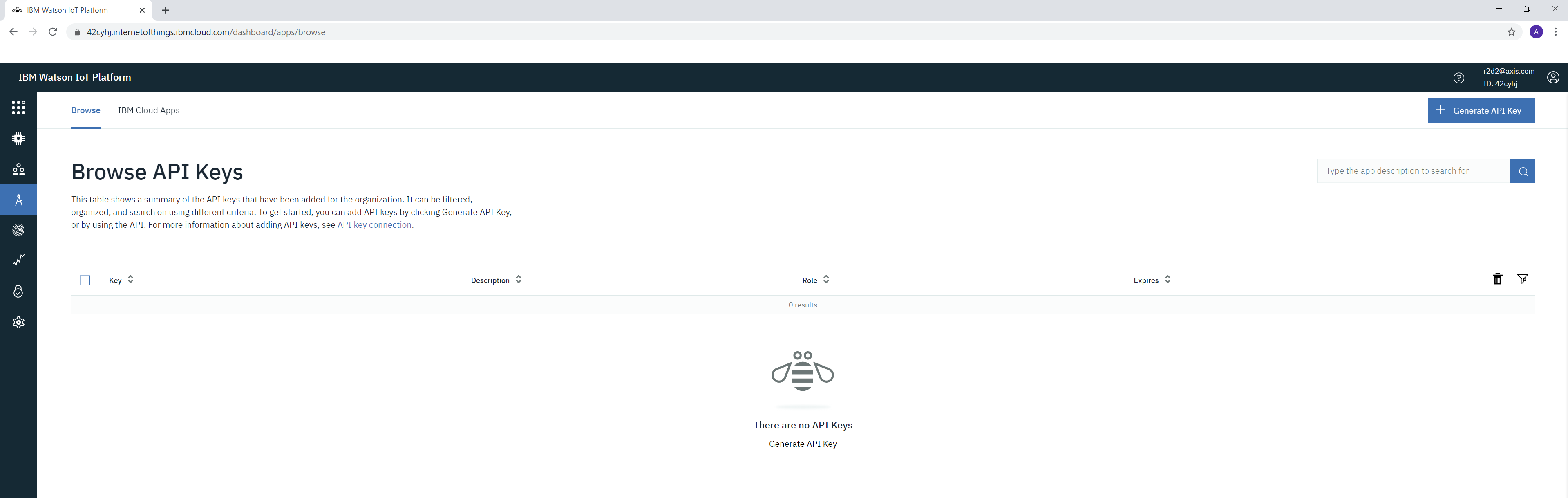
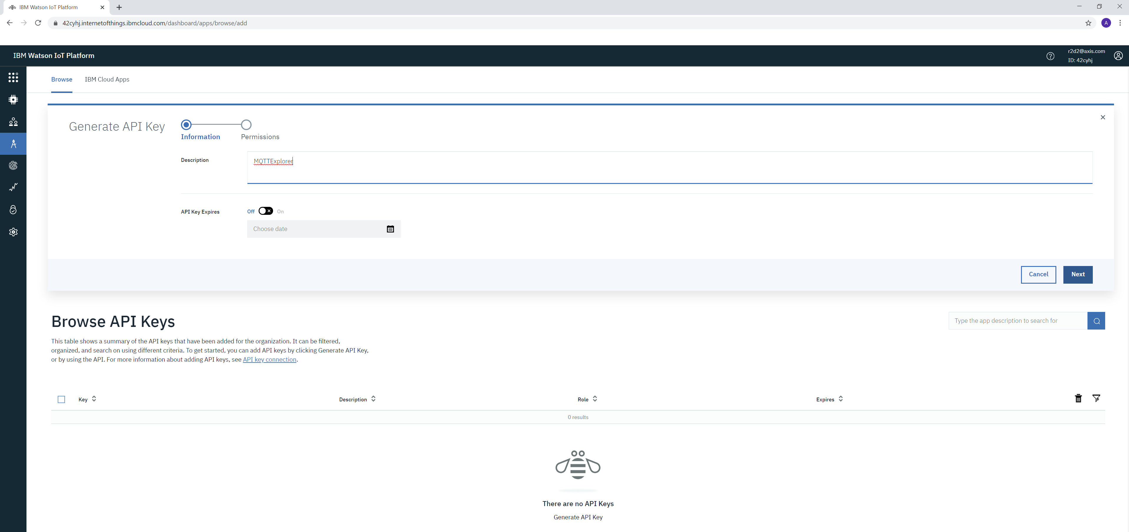
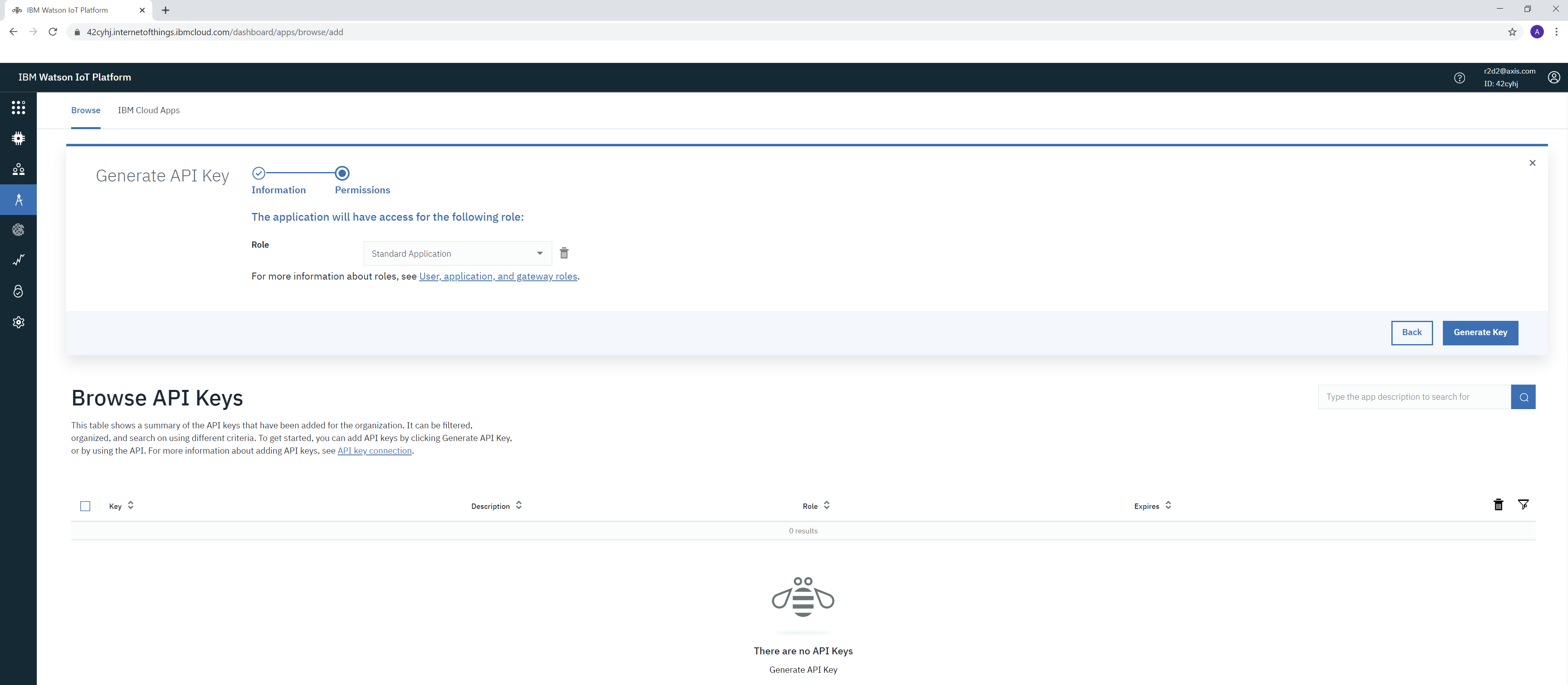
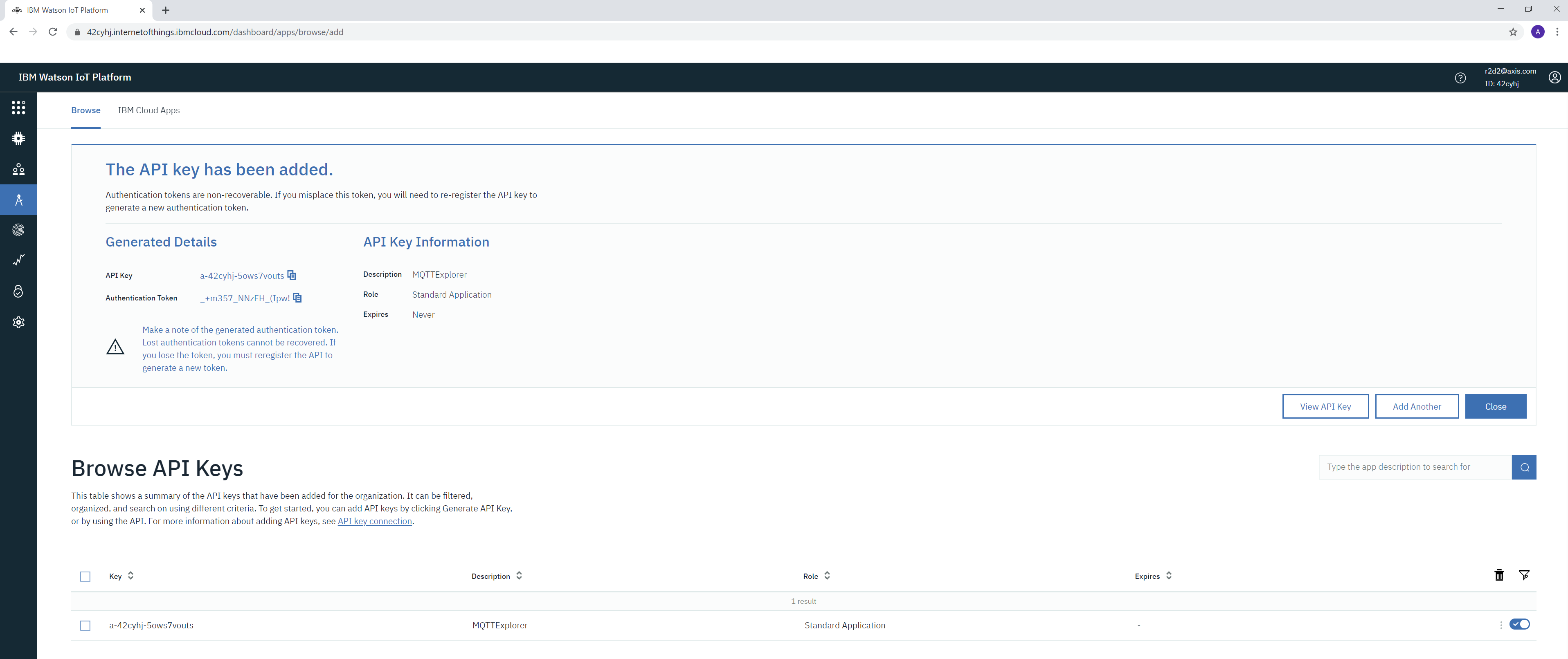
With the newly generated API keys we can connect to the IBM MQTT broker. See example settings below.
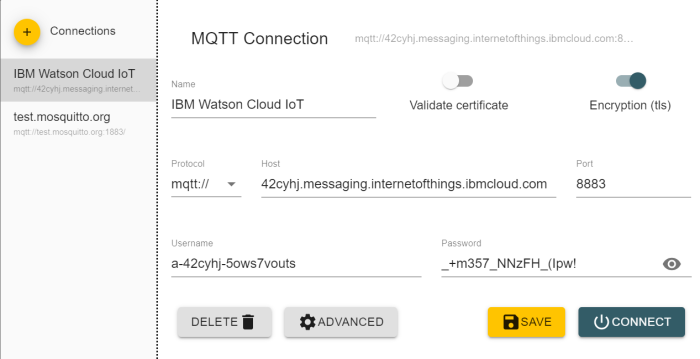
The below subscription topic is mandatory to configure, otherwise no events will be seen. The MQTT client ID must consist of your IBM cloud entity followed by a customizable string (e.g. “mqtt”) that a user can define.
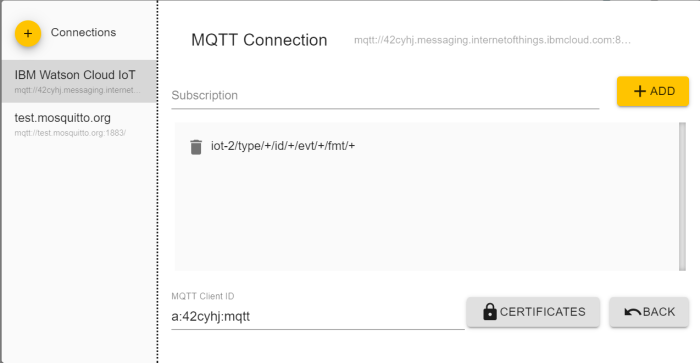
Upon successful connection, events should be sent from the Axis device. The simplest way of testing this is to use the manual trigger in the Axis device.
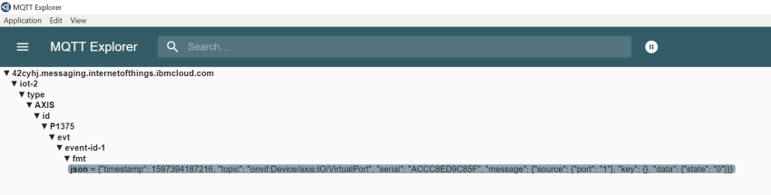
Google Cloud Platform (GCP)
In this section you can read about the configuration steps required to connect an Axis device to a Google Cloud Platform (GCP) MQTT broker in order to publish topics. For further reading, go to https://cloud.google.com/iot/docs/how-tos/gateways/mqtt-bridge and https://cloud.google.com/iot/docs/how-tos/mqtt-bridge.
The below steps illustrate basic integration and use-cases within a test lab environment. Axis strongly recommends following the provider’s guidelines for an integration that maximizes the handling of certificates, tokens, user-credentials and overall cybersecurity in a production environment.
Step 1: Pub/Sub configuration
In the first step, we will use Google’s Pub/Sub hub. Pub/Sub is used to create topics so that a device can publish its MQTT events to GCP. In addition, one can also subscribe directly to the topics.

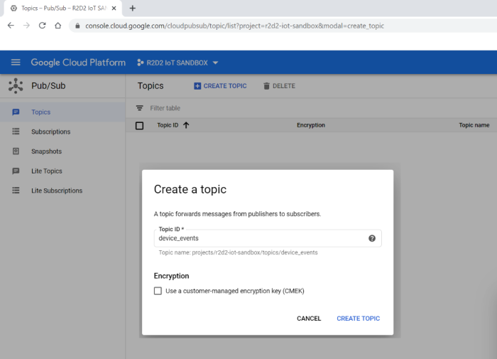
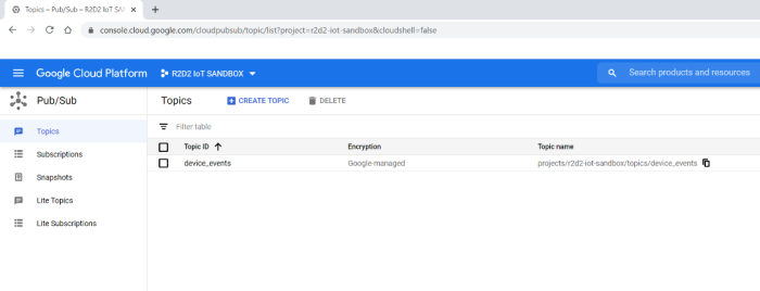
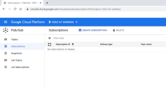
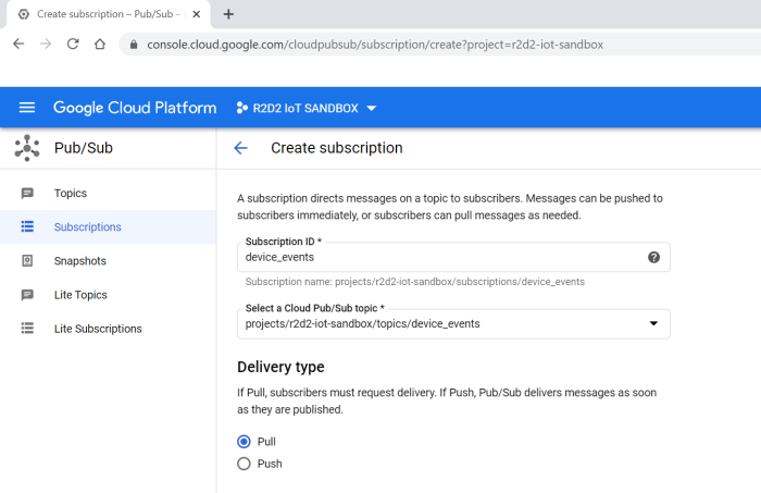
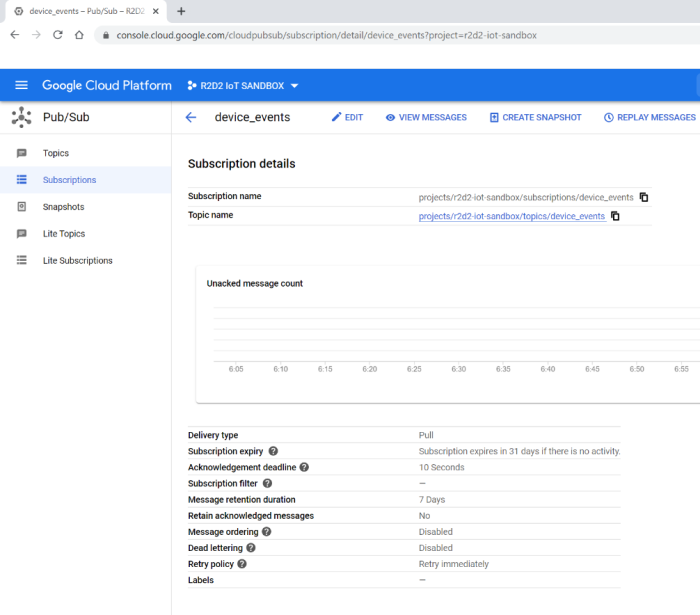
Step 2: GCP MQTT bridge configuration
In this step of the configuration we add a registry point so we can add devices that later on can publish topics. We will use the IoT Core tab for the configuration.

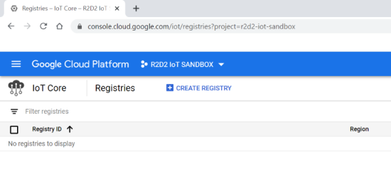
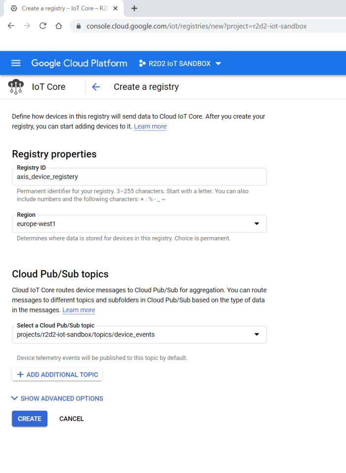
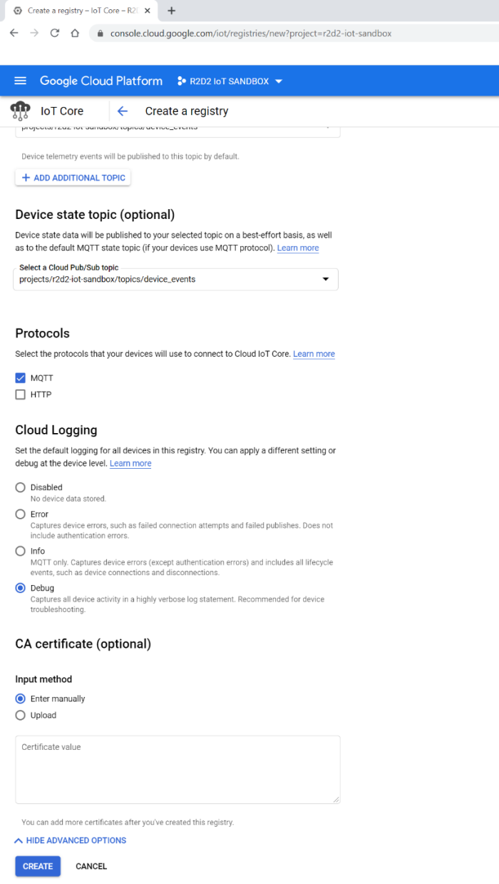
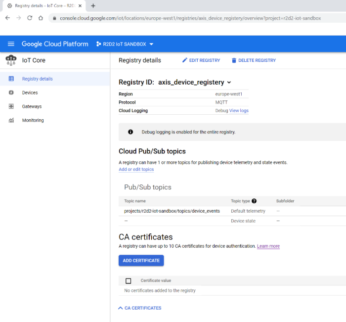
Step 3: GCP device configuration
After creating the registry point, we can now bind devices to it. The devices will then be able to publish topics.
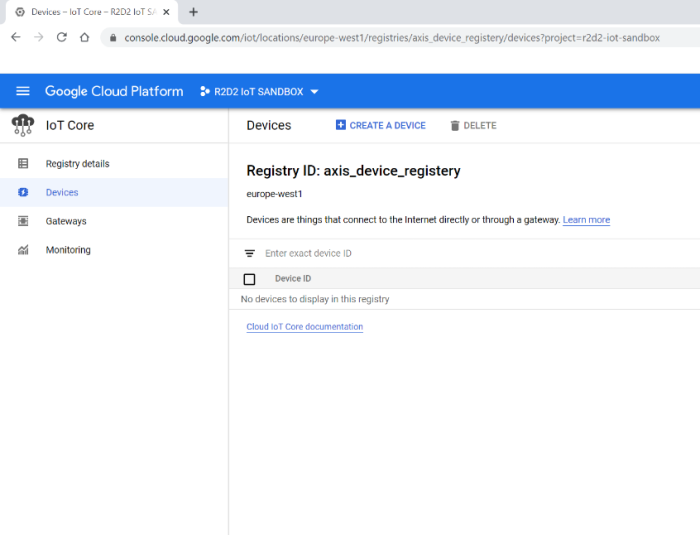
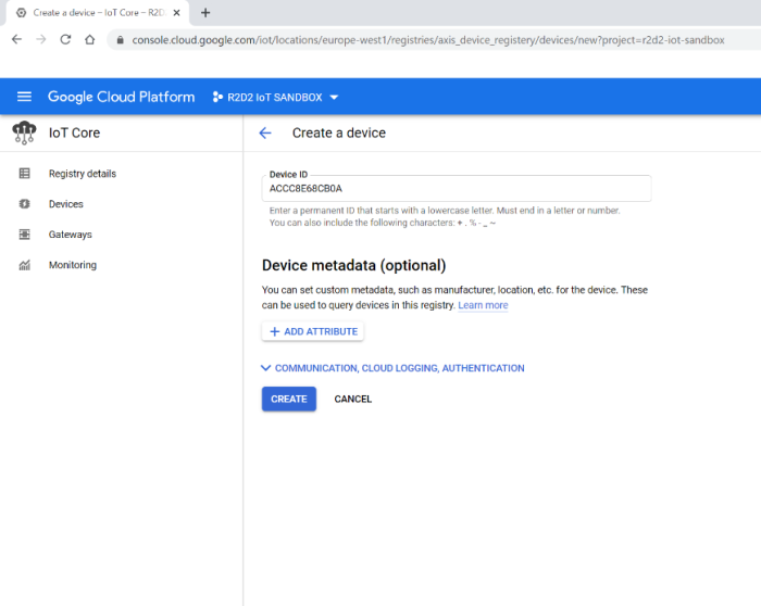
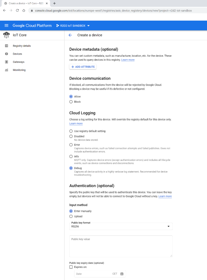
In order to authenticate a device in GCP, a JWT token needs to be used as password for each device, and GCP also needs to bind the public key to decrypt the traffic and authenticate the device correctly.
About the JWT token
The JWT token is generated at a later stage using the public and private key.
About the device public key
In order to create a device in GCP, a public key is needed to authenticate and decrypt traffic from the device. For a test environment, public and private keypairs can be generated in the GCP console directly.
openssl genpkey -algorithm RSA -out rsa_private.pem -pkeyopt rsa_keygen_bits:2048
openssl rsa -in rsa_private.pem -pubout -out rsa_public.pem
Read out the public and private key from the GCP console editor. Use the public key directly to create the device. The public key and the private key is also used later on to sign the JWT token.
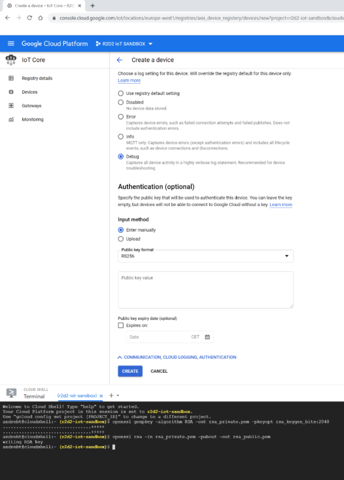
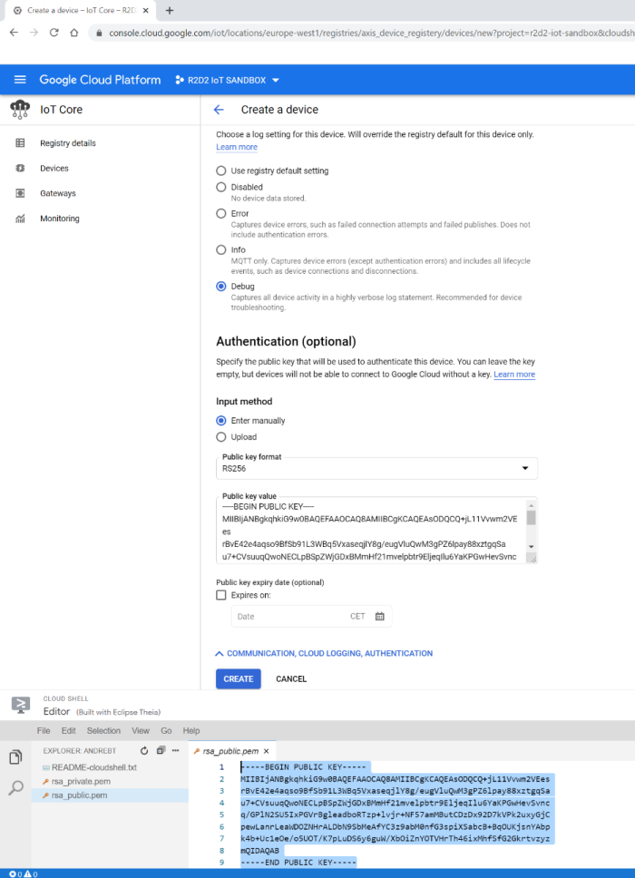
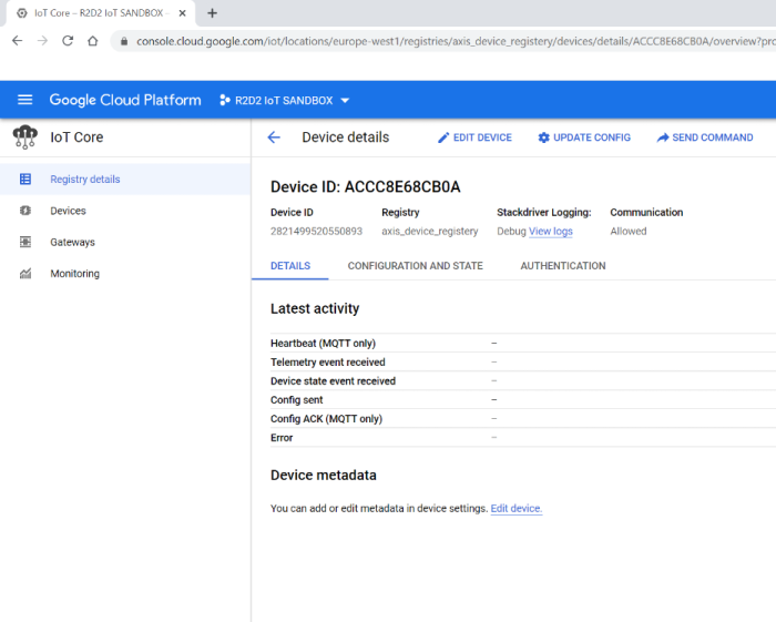
Step 4: JWT token claim
Google Cloud Platform uses JWT token-based authentication. To exemplify, we have used an online tool to generate the JWT token. Note that this is not recommended in a production environment.
The JWT token itself needs the aud (audience), iat (issued-at) and exp (expiration) fields to be available in the JWT token. The iat and exp fields are defined as unix timestamps. These can be used e.g. using this tool. The aud field is defined by the project ID in Google Cloud Platform. When you are done with aud, iat and exp, paste the public and private keypair into the JWT claim in order to export the JWT token as a password for the Axis device.
Important: Google Cloud Platform will reject any authentication attempts with a JWT token that has a longer duration than 24 hours in total.
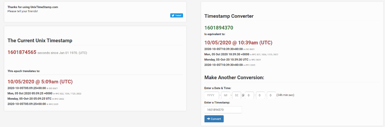
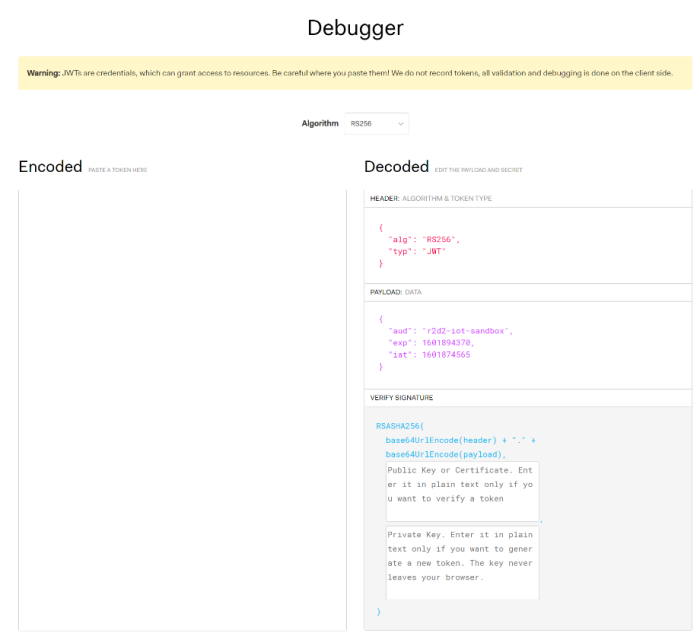
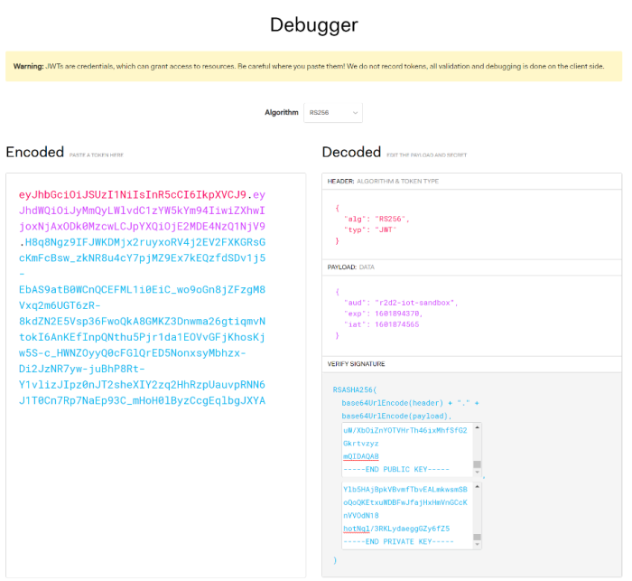
Step 5: Axis device configuration
Below is the actual Axis device configuration for MQTT. Observe the settings required for a successful connection. The username is ignored/not respected in GCP. The client ID uses the following naming convention format, and the parts marked in bold are individual to your configuration illustrated previously:
projects/r2d2-iot-sandbox/locations/europe-west1/registries/axis_device_registery/devices/ACCC8E68CB0A
The password is the JWT token that has been generated previously. The custom condition prefix for event publication uses the following convention and depends on your previously made configuration:
/devices/ACCC8E68CB0A/events
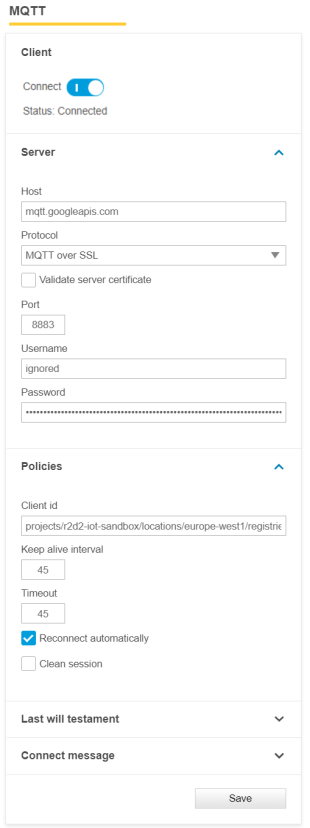 | 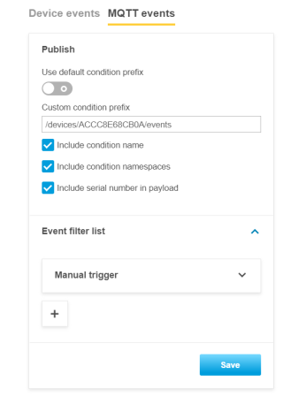 |
Step 6: listen to MQTT events
Google Cloud Platform has its own tools to listen to incoming MQTT events from devices either using the Pub/Sub hub or the GCP console directly by using the command below. Again, the part marked in bold is depending on your previous configuration.
gcloud pubsub subscriptions pull device_events
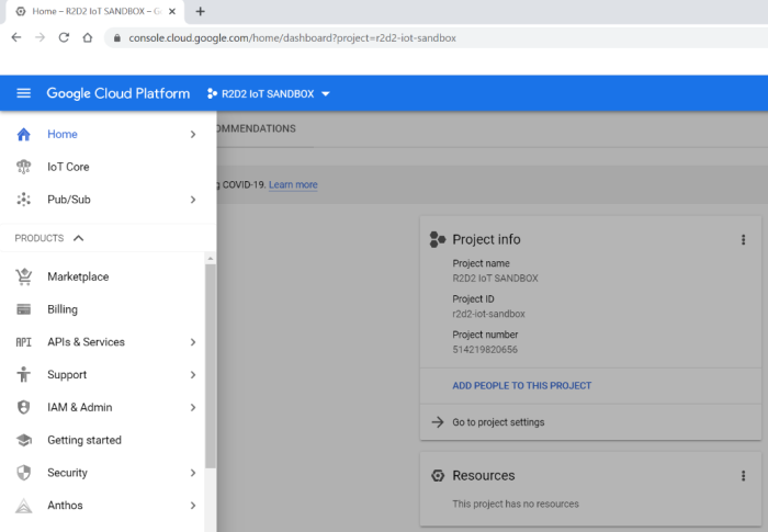
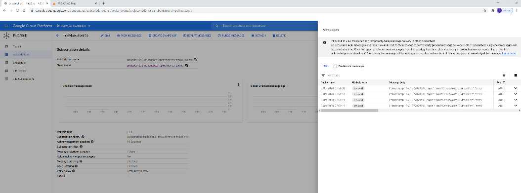
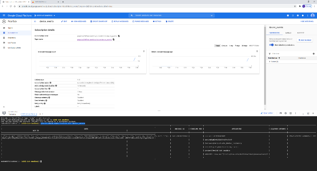
OAuth 2.0 OpenID Connect
Using the OAuth 2.0 OpenID Connect protocol, AXIS OS devices running version 11.6 or later can be integrated into an IT infrastructure with centralized Identity and Access Management (IAM). This allows federated identities to be used for authenticating to the Axis device, eliminating the need for local user management entirely.
OpenID Connect is a standardized authentication and authorization protocol built on top of OAuth 2.0. It enables the use of identities from various Identity Providers or Active Directory Federation Services (ADFS) solutions, such as Microsoft Active Directory, Microsoft Azure AD, Curity Identity Server, and others.
To view a complete list of OpenID Connect certified solutions, go to the official OpenID Connect page. Depending on the feature set of the Identity Provider, the following security mechanisms could be used to allow for further enhanced secure identity-based authentication towards the Axis device:
Multi-Factor Authentication (MFA)
Password Complexity Enforcement
Password Rotation
Time-limited authentication
Centralized identity (user/service account) management
Benefits
Increased security by avoiding local device user account information leakage.
Axis devices integrate seamlessly into IT-infrastructure supported secure Identity and Access Management (IAM).
HTTP(S) web-interface access and tunneled video streaming is supported.
IT enforced IAM security policies, traceability, and security audit logging.
Limitations
The following limitations/considerations need to be taken into account when the Axis device is operated in OAuth 2.0 mode:
The Video or Device Management System that is connecting to the Axis device also needs to support OAuth 2.0 to interact with the Axis device. Contact your third-party Video and Device Management System vendor for further information.
Video Streaming through RTSP-server authentication is not supported.
AXIS Device Management solutions (ADM5, ADMX) as well as AXIS Companion and AXIS Camera Station are currently not supported.
Legacy setup with HTTP(S) Basic/Digest only
Hybrid setup with HTTP(S) Basic/Digest and OAuth 2.0 Authorization Code Flow
Fully adapted setup with OAuth 2.0 Client Credential Grant and OAuth 2.0 Authorization Code Flow
Authorization Code Flow (human to machine)
The Authorization Code Flow is an OAuth 2.0 process meant for human to machine communication where an actual user logs into the Axis device typically using a username and password or via federated login through an identity provider.
In this flow, available with AXIS OS 11.7 and later, the user is redirected to the identity provider to authenticate and give consent. Once approved, the application receives an authorization code, which it exchanges for an access token. This token allows the application to access the Axis device on behalf of the logged-in user. Unlike machine-to-machine flows, the Axis device can associate the request with a specific user identity, enabling user-specific access control and auditing.
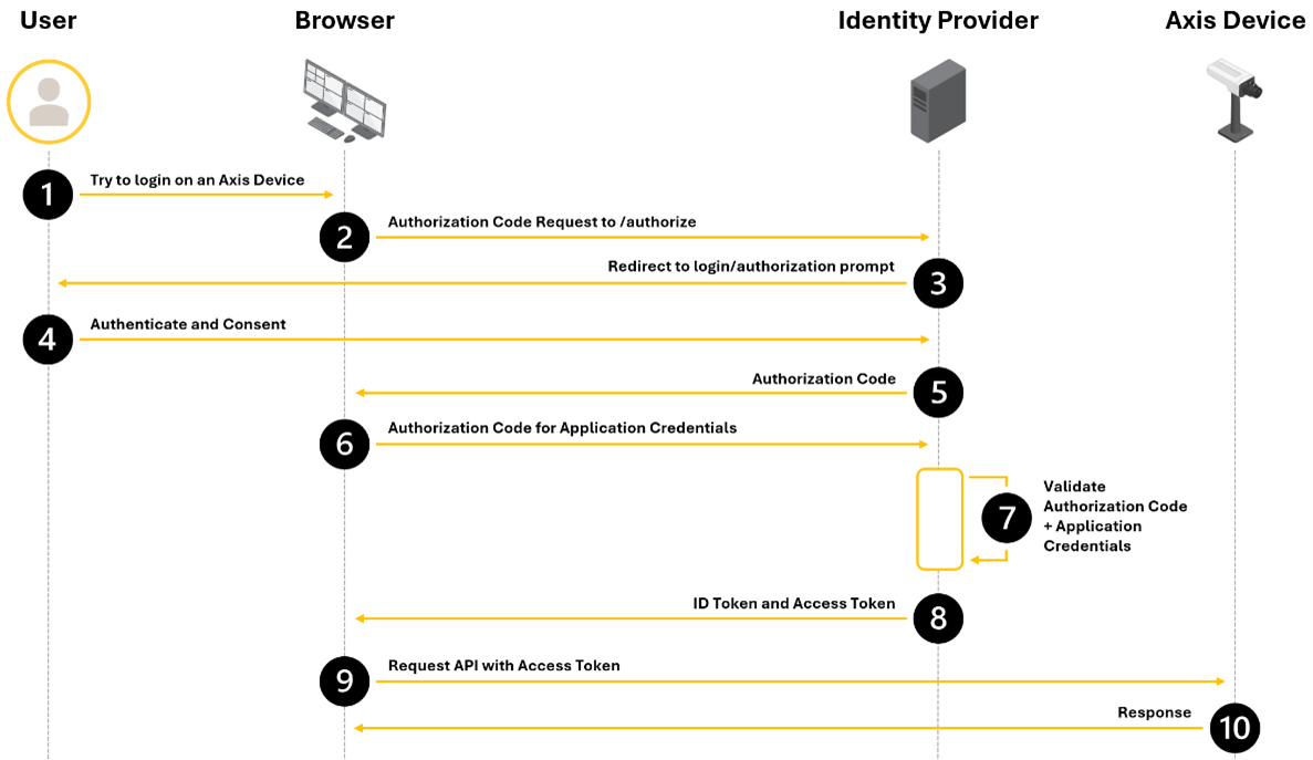
Axis device configuration
This section only covers the OAuth 2.0 OpenID Connect parameters. To enable OAuth 2.0 OpenID Connect Authorization Code Flow, you need to configure a virtual host. See Authentication schemes for more information how to configure a virtual host.
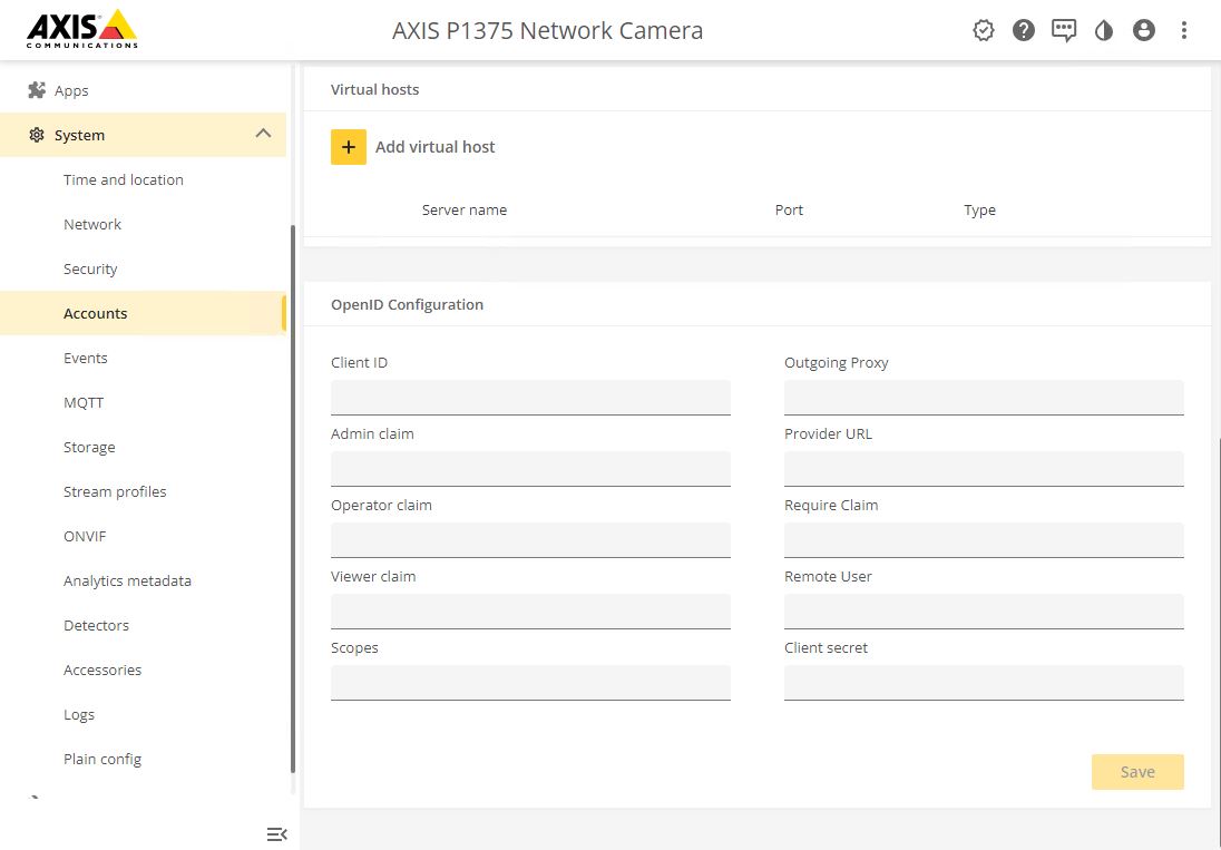
While the above example shows the configuration using the built-in web interface, it is also possible to use the available OpenID Connect Setup VAPIX API to configure the required OpenID Connect parameters on an Axis device. Using AXIS Device Manager, the required settings can be pushed to multiple devices at once.
Parameter | Value | |
Client ID | The client ID (or application ID) issued by the Identity Provider. | |
Admin claim | See User roles for more information. | |
Operator claim | See User roles for more information. | |
Viewer claim | See User roles for more information. | |
Scopes | Optional list of additional OpenID Connect (OIDC) scopes, for example: openid. | |
Outgoing proxy | If applicable, specify the outgoing proxy here. | |
Provider URL | Metadata URL from the Identity Provider (typically located at /.well-known/openid-configuration). | |
Require claim | A specific piece of user information (a claim) that the browser requests and expects to be present in the ID token or response. | |
Remote user | This value is used by the Axis web interface to display the logged-in user's identity. Possible values can be found in the claims_supported field in the provider metadata URL. Examples include "sub" or "unique_name". | |
Client secret | The client secret corresponding to the application ID issued by the Identity Provider. | |
Example login
Browse to
https://<hostname>/of the Axis device, for examplehttps://p1375.axis.com.The device should now redirect to the configured redirect URL of the Identity Provider. This example shows the redirect page of a Azure application.
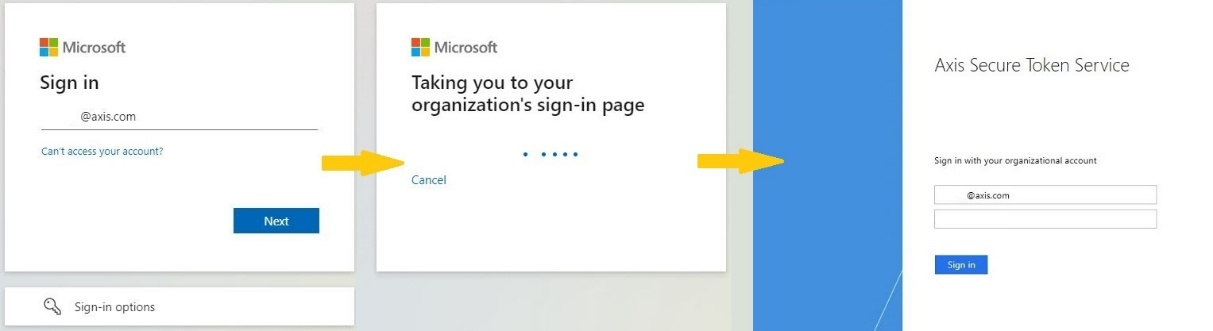
After providing the user identity to the identity provider, you are redirected back to the Axis device interface.
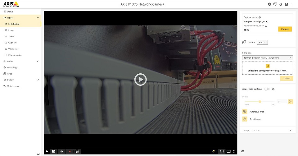
Client Credentials Grant (machine to machine)
The earlier scenario describes a human-to-machine situation, where an actual user logs into the Axis device, typically using credentials or federated authentication through an identity provider. In contrast, the Client Credentials Flow or Client Credentials Grant in OAuth 2.0 is used in machine-to-machine authentication and authorization.
In this flow, available with AXIS OS 12.4 and later, there is no end-user involved. Instead, a service or application (such as a Video or Device Management System) authenticates directly with the identity provider using its own credentials to obtain an access token. This token can then be used to access the Axis device. The Axis device has no visibility into any specific user identity, since the request is made on behalf of the service account, not a person.
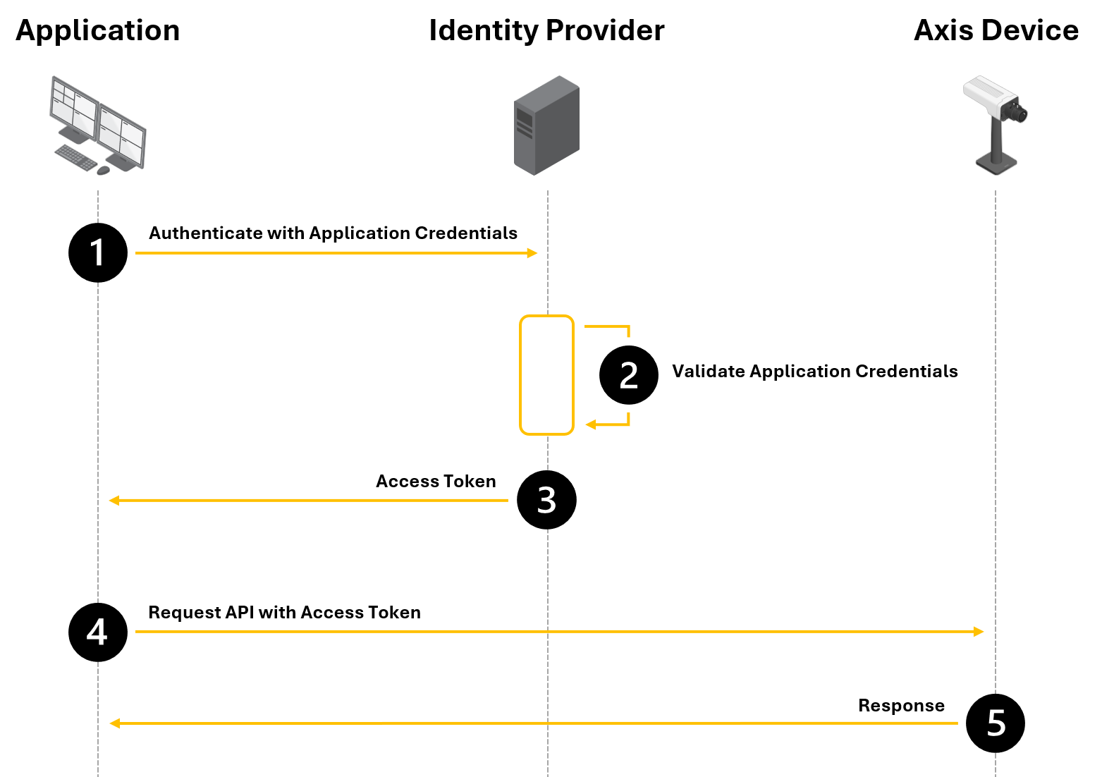
Axis device configuration
This section only covers the OAuth 2.0 OpenID Connect parameters. To enable OAuth 2.0 OpenID Connect Authorization Code Flow, you need to configure a virtual host. See Authentication schemes for more information how to configure a virtual host.
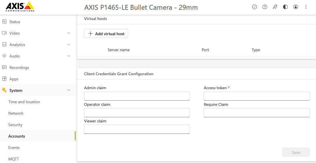
While the above example shows the configuration using the built-in web interface, it is also possible to use the available OpenID Connect Setup VAPIX API to configure the required OpenID Connect parameters on an Axis device. Using AXIS Device Manager, the required settings can be pushed to multiple devices at once.
Parameter | Value | |
Admin claim | See User roles for more information. | |
Operator claim | See User roles for more information. | |
Viewer claim | See User roles for more information. | |
Verification URL | The verification URL or token endpoint is a URL exposed by the Identity Provider. | |
Require claim | A specific piece of user information (a claim) that the application requests and expects to be present in the ID token or response. | |
Example login
We’ll use Postman in this example to demonstrate how the OAuth 2.0 OpenID Connect Client Credentials Grant works.
Pick the request you'd like to authorize (for example, a GET or POST to a protected API).
Go to the Authorization tab > type:
OAuth 2.0
> Click Get New Access Token.Fill in the token details as provided by your identity provider.
Click Get Token > Postman will send a request to the token URL and get an access_token back.
Click Use Token. This attaches the token to your request's Authorization: Bearer <token> header.
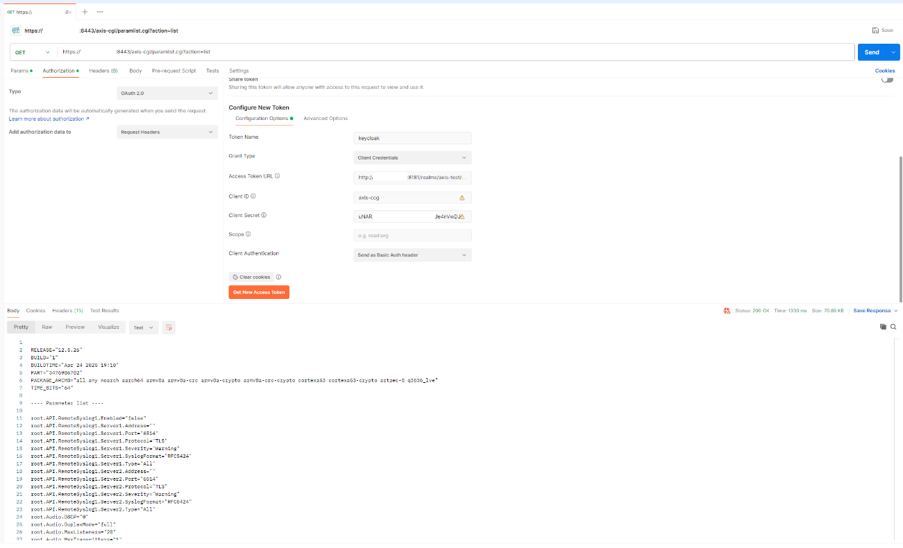
User roles
Axis devices know 3 different roles when using the OAuth 2.0 OpenID Connect Authorization Code Flow:
Administrator (with PTZ rights)
Operator (with PTZ rights)
Viewer (without PTZ rights)
To illustrate a setup with different user roles, the following security groups have been created in an Active Directory, each containing different users.
Active Directory group name | Group members | |
Axis-Lund-admin | User1 | |
Axis-Lund-operator | User2 | |
Axis-Lund-viewer | User3 | |
Depending on the identity provider, a custom claim may need to be configured so the above Active Directory Group information is part of the information in the ID token that is provided by the Identity Provider. For this example, the claim name "groups" has been configured on the identity provider to include the Active Directory Group membership. When a user belongs to a group, the group name will be included in the user’s profile.
To link Active Directory groups to the Axis user roles, the following values should now be used in the Axis device parameter configuration.
Parameter | Value | |||||||||||||||||
Admin claim | groups:Axis-Lund-admin | |||||||||||||||||
Operator claim | groups:Axis-Lund-operator | |||||||||||||||||
Viewer claim | groups:Axis-Lund-viewer | |||||||||||||||||
This will result with the following user roles being assigned to the earlier created user.
User1 | Administrator with PTZ rights | |||||||||||||||||||||||||||||||||
User2 | Operator with PTZ rights | |||||||||||||||||||||||||||||||||
User3 | Viewer without PTZ rights | |||||||||||||||||||||||||||||||||
Curity Identity Server
In this section you can read about the configuration steps required to connect an Axis device to a Curity Identity Server. Please see the Curity website for further reading about the Curity Identity Server.
The below steps illustrate basic integration and use-cases within a test lab environment. Axis strongly recommends following the provider’s guidelines for an integration that maximizes the handling of certificates, tokens, user-credentials and overall cybersecurity in a production environment.
Curity Identity Server setup
Following the getting started guide described on the Curity website should supply you with a basic setup to integrate an Axis device into Curity Identity Server. Please note you should configure trusted certificates. Please refer to the Curity Identify Server documentation on how this is done.
Navigate to Token Service >Client and create a new client. Enter a client id and document it.
Add a new capability, choose Code Flow and Introspection.
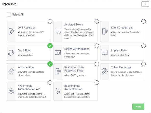
Define a redirect URI. This should be device unique.
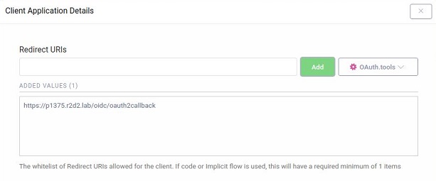
Define a client secret and document it.
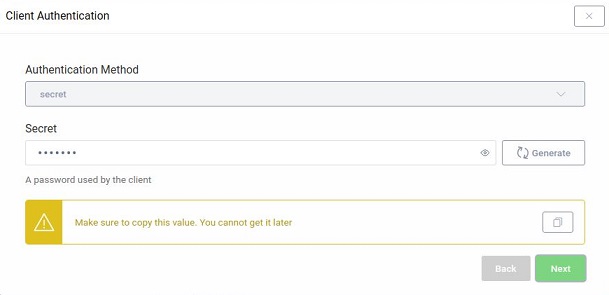
Define a user authentication method. During the getting started steps a default username-password page was created which we use in this example.
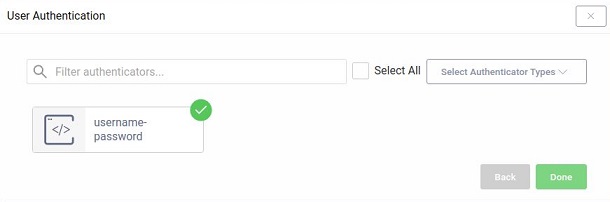
Add a scope and enter email, openid and profile.
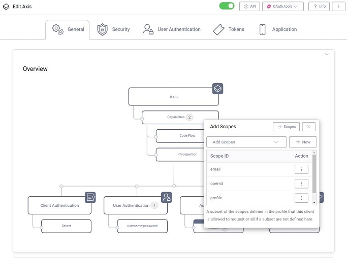
The overview now should look like this:
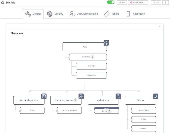
In the Security tab, under Origins and Validation, please add the hostname of your device.
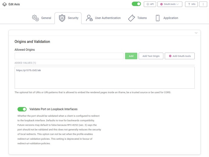
Under Changes in the menu, select to Commit your changes.
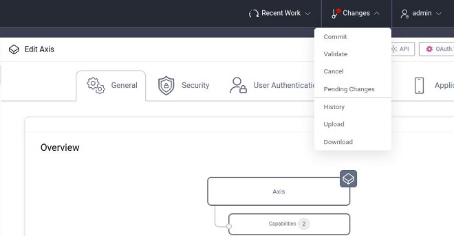
- Axis device parameters
Parameter Value Admin claim Value of the issuer property from the ProviderMetadataURL.
Example: “iss:https://curity_server/oauth/v2/oauth-anonymous”Operator claim Value of the issuer property from the ProviderMetadataURL.
Example: “iss:https://curity_server/oauth/v2/oauth-anonymous”Viewer claim Value of the issuer property from the ProviderMetadataURL.
Example: “iss:https://curity_server/oauth/v2/oauth-anonymous”Client ID The client ID obtained during step 2. Client secret The client secret obtained during step 10 Outgoing Proxy Not used in this example but if required for your setup, specify here the outgoing proxy. Provider URL https://curity_server/oauth/v2/oauth-anonymous/.well-known/openid-configuration Remote User This is the value used by the web interface to display the logged-in user.
Possible values can be found in the ProviderMetadataURL > claims_supported. Example: “sub”Require Claim Value of the issuer property from the ProviderMetadataURL.
Example: “iss:https://curity_server.com”Scopes Optional list of additional OIDC scopes.
Google Cloud Platform
In this section you can read about the configuration steps required to connect an Axis device to the Google Cloud Platform using OpenID Connect. For further reading, please review the Google Identity documentation.
The below steps illustrate basic integration and use-cases within a test lab environment. Axis strongly recommends following the provider’s guidelines for an integration that maximizes the handling of certificates, tokens, user-credentials and overall cybersecurity in a production environment.
Google Cloud Platform setup
Setup a project in the Google API Console.
Click on Select project and select New project.
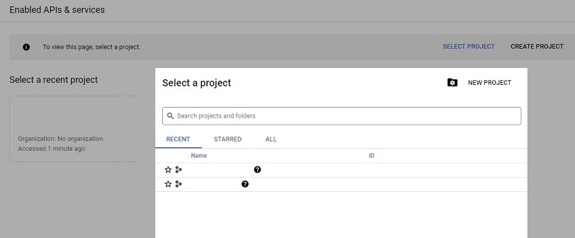
Enter a Project name and click on Create.
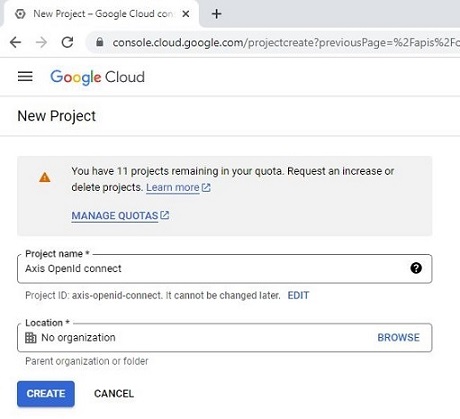
To setup OAuth 2.0, go to OAuth consent screen page and select user type.
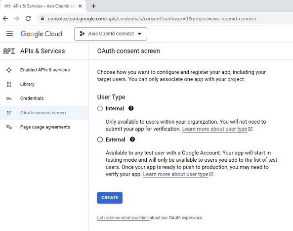
Enter the required details.
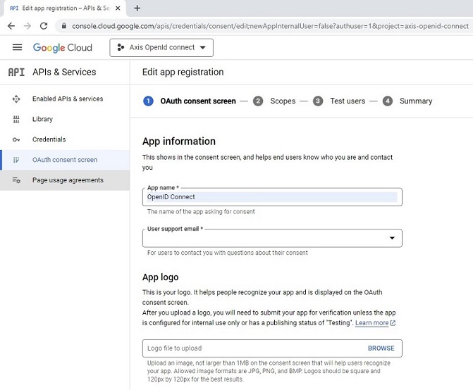
Add the scopes: userinfo.email, userinfo.profile and openid.
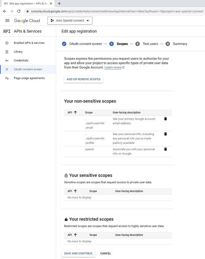
Add authenticated users to the application.
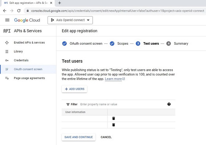
To obtain OAuth 2.0 credentials, go to the Credentials page.
Select Create credentials > OAuth client ID.
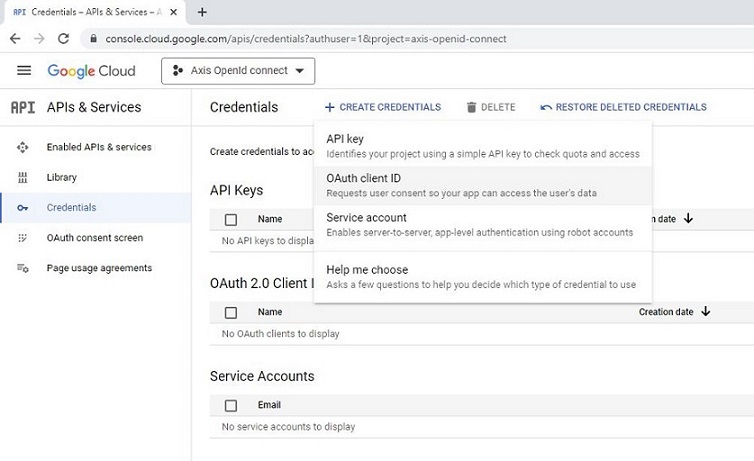
Select application type Web application, fill in a client name and configure authorized redirect URIs. Note that this the FQDN should end with “/oidc/oauth2callback”.
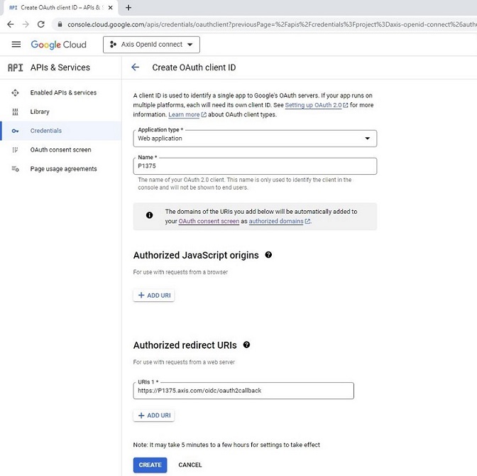
Document the Client ID and Client secret for further usage.
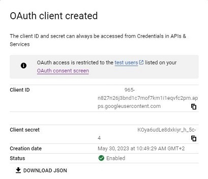
- Axis device parameters
| Parameter | Value | |
| Admin claim | https://accounts.google.com | |
| Operator claim | https://accounts.google.com | |
| Viewer claim | https://accounts.google.com | |
| Client ID | The client ID obtained during step 8. | |
| Client secret | The client secret obtained during step 8. | |
| Outgoing Proxy | Not used in this example but if required for your setup, specify here the outgoing proxy. | |
| Provider URL | https://accounts.google.com/.well-known/openid-configuration | |
| Remote User | This is the value used by the web interface to display the logged in user. Possible values can be found in the ProviderMetadataURL > claims_supported. Example: “sub” | |
| Require Claim | Value of the issuer property from the ProviderMetadataURL. Example: “iss:https://accounts.google.com” | |
| Scopes | Optional list of additional OIDC scopes. | |
Microsoft Identity Platform (Azure)
In this section you can read about the configuration steps required to connect an Axis device to the Microsoft Identity Platform using OpenID Connect. For further reading, please review the Microsoft Identity Platform documentation.
The below steps illustrate basic integration and use-cases within a test lab environment. Axis strongly recommends following the provider’s guidelines for an integration that maximizes the handling of certificates, tokens, user-credentials and overall cybersecurity in a production environment.
Microsoft Identity Platform setup
Setup an application in the Microsoft Azure Active Directory console.
Go to the App registrations page and select New registration.
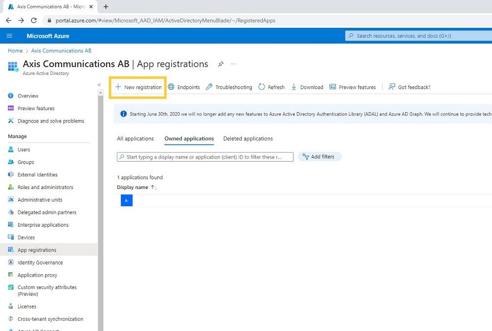
Fill in a display name and configure an authorized redirect URI. Note that this the FQDN should end with “/oidc/oauth2callback”.
Document the Application (client) ID.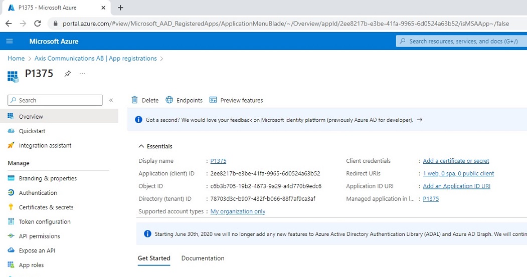
To obtain a client secret, go to the Certificates & secrets page and select New client secret.
Fill in a description and expiry date and click Add. Document the Client secret.
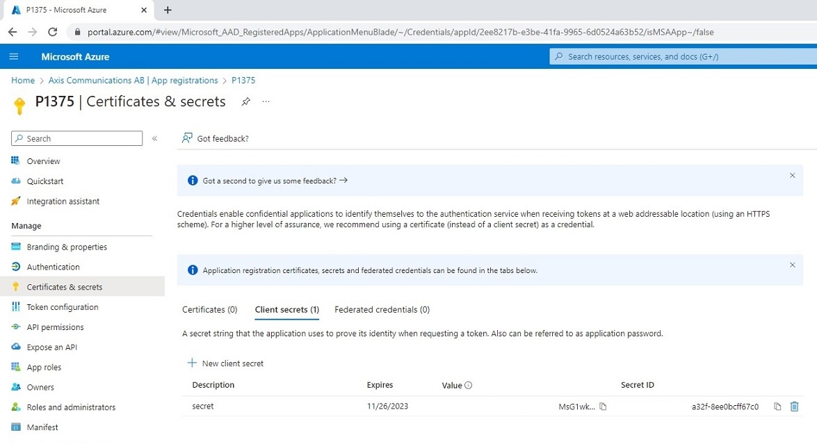
Go to the Overview page and select Endpoints and document the shown endpoints.

Axis device parameters
| Parameter | Value | |
| Admin claim | Value of the issuer property from the ProviderMetadataURL. Example: “iss:https://login.microsoftonline.com/78703d3c-b907-432f-b066-88f7af9ca3af/v2.0” | |
| Operator claim | Value of the issuer property from the ProviderMetadataURL. Example: “iss:https://login.microsoftonline.com/78703d3c-b907-432f-b066-88f7af9ca3af/v2.0” | |
| Viewer claim | Value of the issuer property from the ProviderMetadataURL. Example: “iss:https://login.microsoftonline.com/78703d3c-b907-432f-b066-88f7af9ca3af/v2.0” | |
| Client ID | The client ID obtained during step 3. | |
| Client secret | The client secret obtained during step 5 . | |
| Outgoing Proxy | Not used in this example but if required for your setup, specify here the outgoing proxy. | |
| Provider URL | OpenID Connect metadata document obtained during step 3. | |
| Remote User | This is the value used by the web interface to display the logged in user. Possible values can be found in the ProviderMetadataURL > claims_supported. Example: “sub” | |
| Require Claim | Value of the issuer property from the ProviderMetadataURL. Example: “iss: https://login.microsoftonline.com/78703d3c-b907-432f-b066-88f7af9ca3af/v2.0” | |
| Scopes | Optional list of additional OIDC scopes. | |
Microsoft Windows AD FS
In this section you can read about the configuration steps required to connect an Axis device to Microsoft Windows Active Directory Federation Service (AD FS) using OpenID Connect. For further reading, please review the Windows AD FS documentation.
The below steps illustrate basic integration and use-cases within a test lab environment. Axis strongly recommends following the provider’s guidelines for an integration that maximizes the handling of certificates, tokens, user-credentials and overall cybersecurity in a production environment.
Windows AD FS setup
Install the Windows AD FS role as described here.
Configure the Windows AD FS role as described here.
Verify that Windows AD FS is working correctly be following the steps described here
From the Windows AD FS management console, add a new application group. Use the Server Application template.
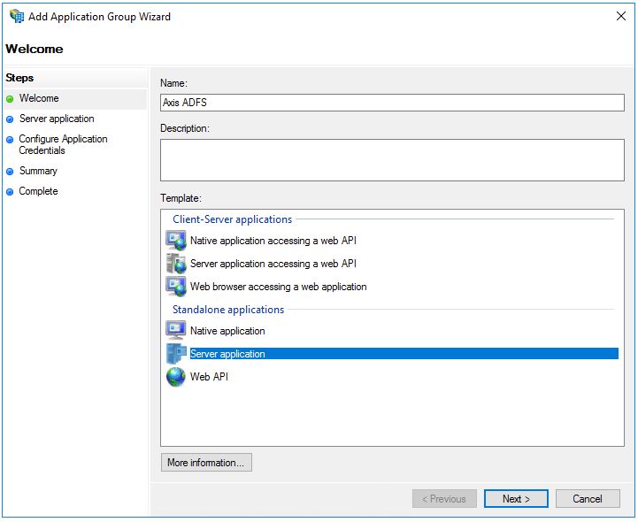
Enter a Name, Client Identifier and Redirect URI. Document the Client Identifier. Note that the redirect URI is the FQDN of the Axis device and it should end with “/oidc/oauth2callback”. Click Next.
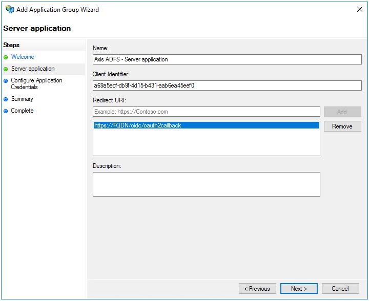
Select Generate a shared secret. Document the shared secret. Click Next.
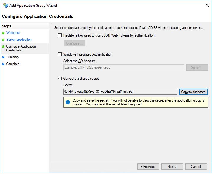
Complete the rest of the wizard.
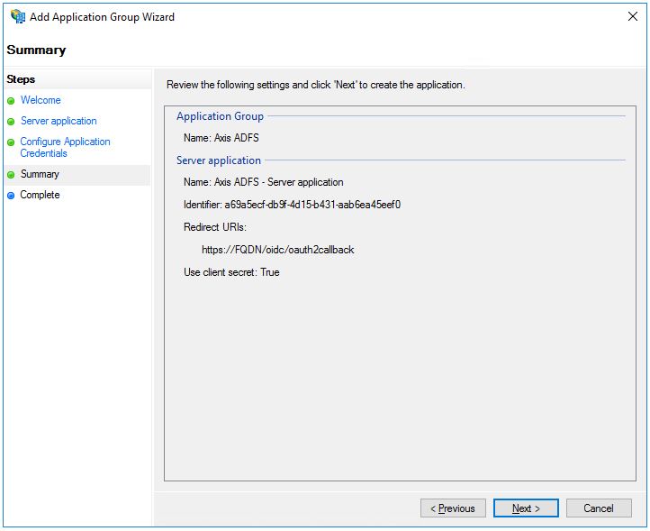
Axis device parameters
| Parameter | Value |
| Admin claim | Value of the issuer property from the ProviderMetadataURL. Example: “iss:https://ADFS_server/adfs/” |
| Operator claim | Value of the issuer property from the ProviderMetadataURL. Example: “iss:https://ADFS_server/adfs/” |
| Viewer claim | Value of the issuer property from the ProviderMetadataURL. Example: “iss:https://ADFS_server/adfs/” |
| Client ID | The client ID obtained during step 5. |
| Client secret | The client secret obtained during step 6. |
| Outgoing Proxy | Not used in this example but if required for your setup, specify here the outgoing proxy. |
| Provider URL | https://ADFS_server/adfs/.well-known/openid-configuration |
| Remote User | This is the value used by the web interface to display the logged in user. Possible values can be found in the ProviderMetadataURL > claims_supported. Example: “sub” or "unique_name". |
| Require Claim | Value of the issuer property from the ProviderMetadataURL. Example: “iss:https://ADFS_server/adfs/” |
| Scopes | Optional list of additional OIDC scopes. |
SFTP (SSH File Transfer Protocol)
Axis devices are capable of sending images and videos using the SFTP (SSH File Transfer Protocol) protocol to a remote server. SFTP is using the secure and encrypted SSH protocol to transfer data via FTP. This is not to be mistaken with FTPS (FTP over SSL), which is another secure method of transferring data securely, however not supported by Axis devices.
3rd party SFTP server
Depending on the environment and selected 3rd party SFTP server, the configuration may differ. In this tutorial we are going to have a look at the commonly used OpenSSH server for Linux operating systems.
The below steps illustrate basic integration and use cases within a test lab environment. Axis strongly recommends following the provider's guidelines for an integration that maximizes the handling of certificates, tokens, user-credentials and overall cybersecurity in a production environment.
OpenSSH server configuration
The SFTP implementation of Axis devices is based on the open-source software component Curl. Out of the many authentication methods that Curl supports, Axis devices currently only support the so called CURLSSH_AUTH_PASSWORD. Therefore you need to make sure that the SFTP server being used supports this method as well.
This guide can be used as a reference to install OpenSSH, which then allows for the Axis device to transfer data using SFTP. Once the OpenSSH server is installed, it should be possible to test that the connections work, e.g. by using Putty (SSH client). Enter the server IP address as well as the login credentials from your Linux operating system to connect.
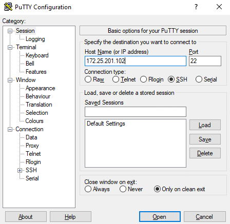
SFTP uses public key authentication in order to allow for secure data transfer, which is why it's recommended to create dedicated key pairs for this purpose. In AXIS OS, SSH-2 with RSA, DSA, ECDSA and ED25519 host keys are supported. AXIS OS 11.1 or higher includes a new OpenSSH version which removes depreciated authentication methods of using RSA keys. We recommend using the SFTP server’s ECDSA or ED25519 host keys instead. By using the following commands, private/public host key pairs can be created in the OpenSSH server. The private key is exclusively used by the OpenSSH server while the public key will be used by the Axis device in form of a hashed MD5 or SHA-256 key that is generated from the public key.
| Command | Description |
|---|---|
| sudo ssh-keygen -t dsa | Creates a private/public DSA host key pair |
| sudo ssh-keygen -t rsa | Creates a private/public RSA host key pair |
| sudo ssh-keygen -t ed25519 | Creates a private/public ed25519 host key pair |
| sudo ssh-keygen -t ecdsa | Creates a private/public ecdsa host key pair |
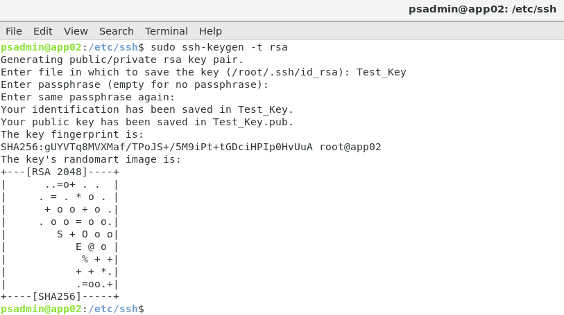
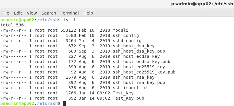
Following the creation of the private/public key pair, we can use the following commands to generate the MD5 and/or SHA-256 hash keys that need to be used in the SFTP recipient configuration in the Axis device (see Axis device configuration). Note that it's possible to create both an MD5 and/or SHA-256 hash key from either of the generated public host keys above. In the below example, we generate an MD5 or a SHA-256 hash key from the different public host keys.
| Command | Example output | Description |
|---|---|---|
| sudo ssh-keygen -l -E md5 -f ssh_host_rsa_key.pub | b800c8958b8679a7bd66c13669051466 | Generates an MD5 hash from RSA public key |
| sudo ssh-keygen -l -E sha256 -f ssh_host_rsa_key.pub | gUYVTq8MVXMaf/TPoJS+/5M9iPt+tGDciHPIp0HvUuA | Generates a SHA-256 hash from RSA public key |
| sudo ssh-keygen -l -E sha256 -f ssh_host_ecdsa_key | xSUNCp2sUM0fvUEJFDq7PWtRoBQej/t5NgwS7NMLI2k | Generates a SHA-256 hash from ECDSA public key |
| sudo ssh-keygen -l -E sha256 -f ssh_host_ed25519_key | 21NFP8emqsMLejiG3Nxco2D64lZhdMiseDmpXiSaTj0 | Generates a SHA-256 hash from ED25519 public key |
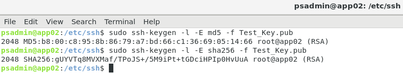
While the Axis device supports both MD5 and SHA-256 hash keys, it's recommended to use SHA-256 due to stronger security over MD5.
Axis device configuration
When creating a new SFTP recipient, please make sure to enter the right MD5 or SHA256 fingerprint of the host key that is used by your SFTP server. Based on the public/private key we created previously and the MD5 or SHA-256 hash keys we generated from the public host key (see 3rd party SFTP server), the SFTP recipient in the Axis device would look as below:
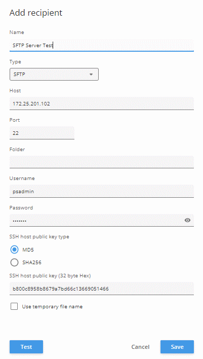
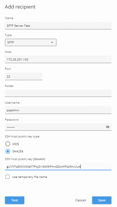
After the SFTP recipient has been created, action rules for image and/or video clip transfer can be created.
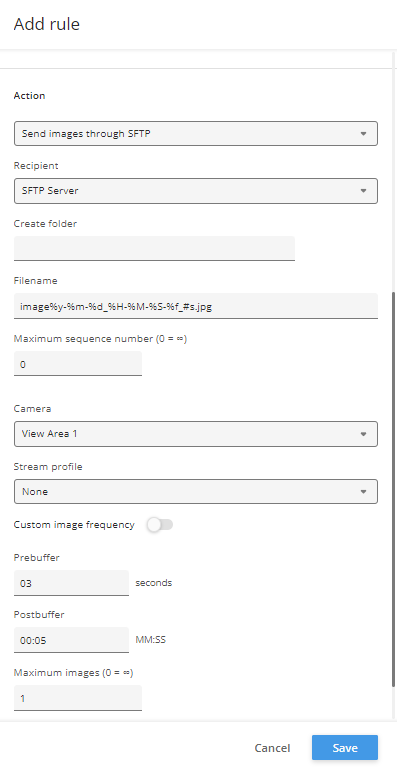
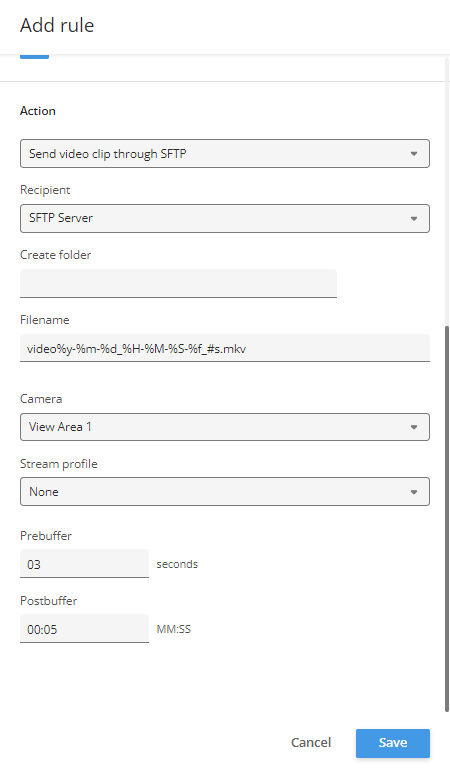
IPv4-compliant mode
Please ensure that the recommended upgrade path is followed prior to upgrading to AXIS OS 12, as deviating from this path may result in the loss of IP settings.
For a long time, the default IP address of Axis devices was 192.168.0.90 when there was no DHCP server available. The link-local address (169.254.0.0/16) was also always on by default. In other words, the camera’s interface had a routable address and an IPv4 link-local address configured concurrently. This is not recommended by the RFC document.
Furthermore, if an Axis device was configured with a static IPv4 address, it would use this IP address regardless of whether another device was already using it on the same network segment, and would cause service interruptions for the other devices.
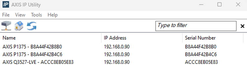
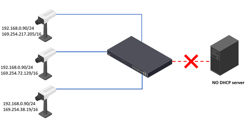
For the aforementioned reasons, we made these changes to IPv4 addressing:
Complete compliance with RFC IPv4
Disable the link-local address when not in use
A better customer experience when multiple factory-defaulted Axis devices are placed on the same network
Addressing conflict detection and resolution
As of AXIS OS 11.7, we added:
A new “Auto Link-local mode”, which is triggered if the static IP address has an addressing conflict, or if a valid DHCP offer is not available.
Address conflict detection for a static IP address. If a conflict is detected, the Axis device will not take an IP address that is in use by another device. Instead, it will fall back to the link-local address (in auto link-local mode).
What do these changes mean for you?
When you have a DHCPv4 server in your network, factory-defaulted Axis devices will take the IP addresses offered by the server. Each device will only have an IPv4 address configured and the link-local address will not be available.
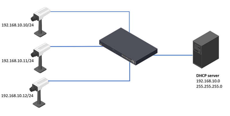
When you don’t have a DHCPv4 server in your network, a factory-defaulted Axis device will not use 192.168.0.90/24 as the default IP address. Instead, a link-local address (169.254.0.0./16) will be configured.
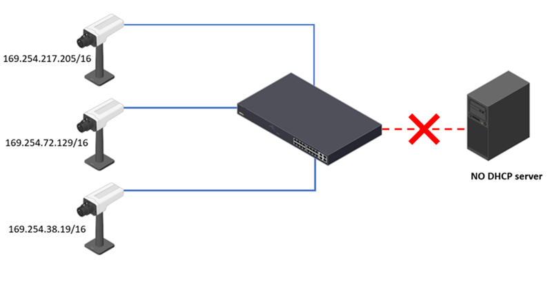
When you manually configure static IP addresses for multiple Axis devices, but you mistakenly assign a single IP address to multiple devices. Only the first device will use that IP address when you connect the devices to the network – all other units will fall back to the link-local address.
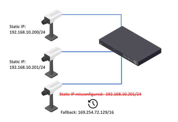
When an Axis device has a static IP address and a second device connects to the network using the same IP address. In keeping with RFC recommendations, the Axis device will defend the IP address and retain it under any circumstances.
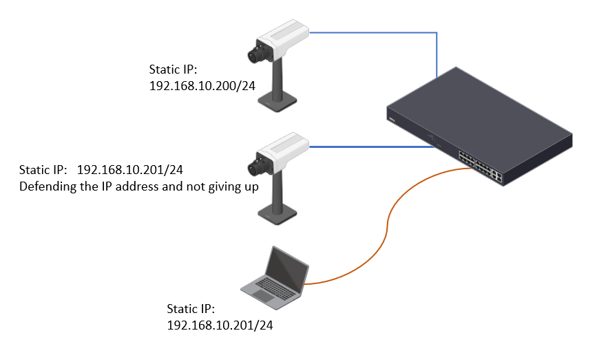
By default, the Axis device will fall back to the link-local address when no DHCP server is available. To make the transition smoother, use the setting (System > Network > IPv4) to select fallback to the static IP address or to the link-local address when DHCP is unavailable.
ON: When DHCP fails to obtain a lease, the static IP address is configured.
OFF: When DHCP fails to obtain a lease, the link-local address is configured.
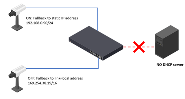
How to find an Axis device if it falls back to the link-local address
First find the network interface card on your computer connecting to the same LAN as the Axis device. The network interface card of the PC should also have a link-local address configured. To configure a link-local address, select one of the following three options.
OPTION 1: Automatically assign a link-local address when the DHCP server is unavailable
Right-click the network interface, select Properties, select Internet Protocol Version 4 (TCP/IPv4), then click on Properties.
Select Obtain an IP address automatically and click OK.
The Windows PC will automatically assign a link-local address to the network interface card.
IP Utility can now discover devices that have fallen back to a link-local address.
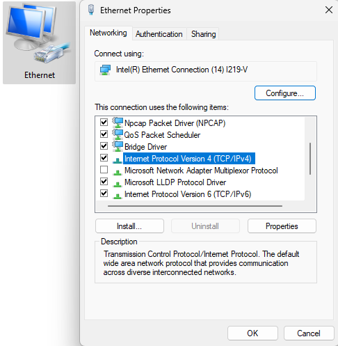
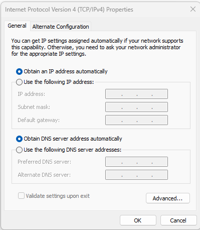
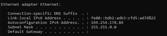
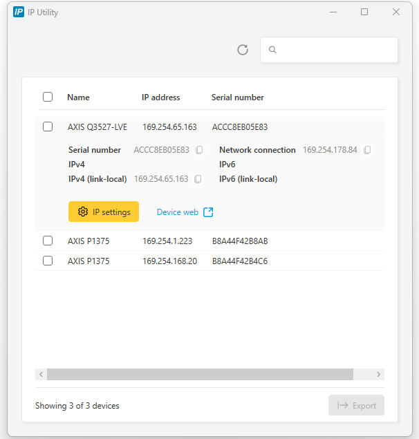
OPTION 2: Manually assign a link-local address when the DHCP server is unavailable
Right-click the network interface, select Properties, select Internet Protocol Version 4 (TCP/IPv4), and then click on Properties.
Manually assign a link-local address. You can use any unused IP address in the range 169.254.0.0/16, with the exception of 169.254.0.0 and 169.254.255.255.
IP Utility can now discover devices that have fallen back to a link-local address.
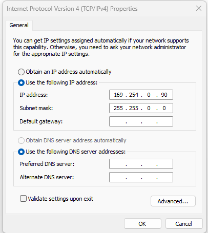
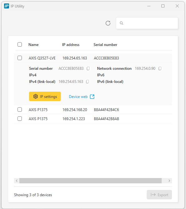
OPTION 3: Add a link-local address to the network interface card when a routable address is configured
Right-click the network interface, select Properties, select Internet Protocol Version 4 (TCP/IPv4), then click on Properties.
If the network interface card already has an IP address 192.168.0.120/24 configured; click Advanced to add an additional link-local address.
Under IP addresses, click Add to add the link-local address. You can use any unused IP address in the range 169.254.0.0/16, with the exception of 169.254.0.0 and 169.254.255.255.
The network interface card should now have two IP addresses configured.
IP Utility can now discover devices that have fallen back to a link-local address.

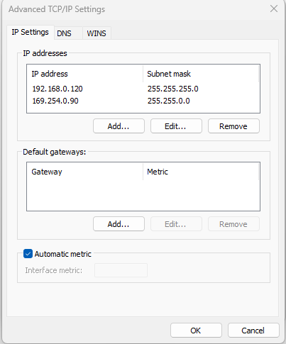
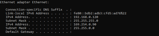
O3C (one-click cloud connection)
O3C (One-Click Cloud Connection) lets you connect your Axis device securely to Axis Cloud Connect. Once connected, the device is accessible through the Axis My Systems web portal and selected Axis partner cloud solutions. To connect your device, you need the Owner Authentication Key (OAK) to verify your ownership when you register it with an Axis Cloud Connect service.
The OAK is included on a printed paper with each Axis device. Keep this document in a safe place – it should not be discarded or disclosed to third parties. If you have lost your OAK, you can retrieve it by logging in to the device as an admin user. Follow one of the paths below, depending on the AXIS OS version of your device.
This requires that the device runs AXIS OS 5.51.7, 6.50.5.2, 8.40.4, 9.80.2, 10.0.0 or higher. Please upgrade if your device is running a lower version. Axis cannot assist in retrieving the OAK for you. For the external retrieval, an outgoing HTTPS (TCP port 443) connection to "oakcgi.o3c.axis.com" needs to be available.
AXIS OS 5.51 & LTS 216 (AXIS OS 6.50)
Go to Setup > Options > Support > System Overview.
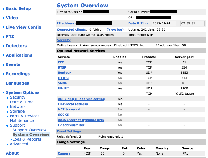
LTS 2018 (AXIS OS 8.40) & LTS 2020 (AXIS OS 9.80)
Go to System > AVHS and click on Get key.
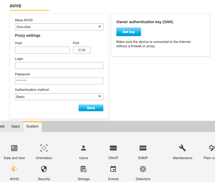
AXIS OS 10.0 or higher
Go to System > O3C and click on Get key.
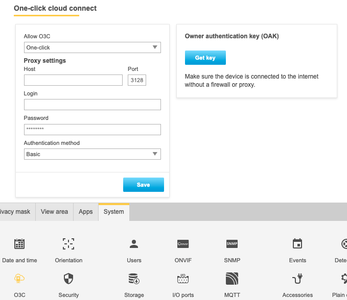
AXIS OS 10.9 or higher
Go to System > Network and click on Get key. Note that this applies to devices with support for the web interface introduced in AXIS OS 10.9. For products that don’t support this web interface, follow the instructions above for AXIS OS 10.0.
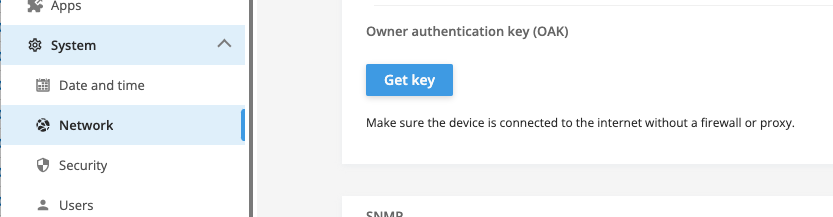
EST (Enrollment over Secure Transport)
Digital certificates are critical for securing devices and networks. but managing them can be complex and time-consuming. Certificates expire and must be renewed regularly. Without automation, this process is repetitive and manual, especially in large deployments or environments with mixed device types.
Device management tools can assist with semi-automated workflows, reducing some of the effort. However, even with such tools, IT teams still need to coordinate processes and perform individual per-device configuration through web interfaces or APIs. Management tasks including initial setup, ongoing maintenance, and monitoring can be time-consuming and the lack of centralized visibility often limits operational efficiency.
What is EST?
AXIS OS 12.9 introduces support for Enrollment over Secure Transport (EST), which is a protocol for securely provisioning certificates to devices. Defined in RFC 7030, EST is a standards-based solution designed to simplify and automate the full certificate lifecycle, including:
Enrollment – securely issuing new certificates to devices
Renewal – automatically replacing expiring certificates
Re-enrollment – updating certificates based on IT policies
EST supports IT-defined policies for certificate attributes, such as validity period, key type (RSA/ECC) or the key size, and it uses HTTPS exclusively.
As EST centralizes certificate management, it gives IT teams improved visibility, monitoring and control over the device certificate lifecycle. Its standard-based design allows integration with a variety of EST servers, including HPE Aruba ClearPass OnBoard, Cisco Identity Services Engine (ISE), Key factor EJBCA and others. This makes EST particularly suitable for IoT/IT environments, enterprise networks, and large-scale device management scenarios, where secure, scalable, and automated onboarding is essential.
Key Benefits of EST
IT-policy managed automated certificate enrollment, renewal, and re-enrollment removing entirely the need for manual, time-consuming configuration.
State-of-the-art secure communication via HTTPS-only TLS 1.2/1.3.
Centralized visibility/monitoring for IT teams.
Standard-based (RFC 7030) and integrates with IT-infrastructure.
Scalable solution for IoT, enterprise networks, and device management.
How EST works
The following is a high-level overview of the steps in an automated certificate enrollment using EST.
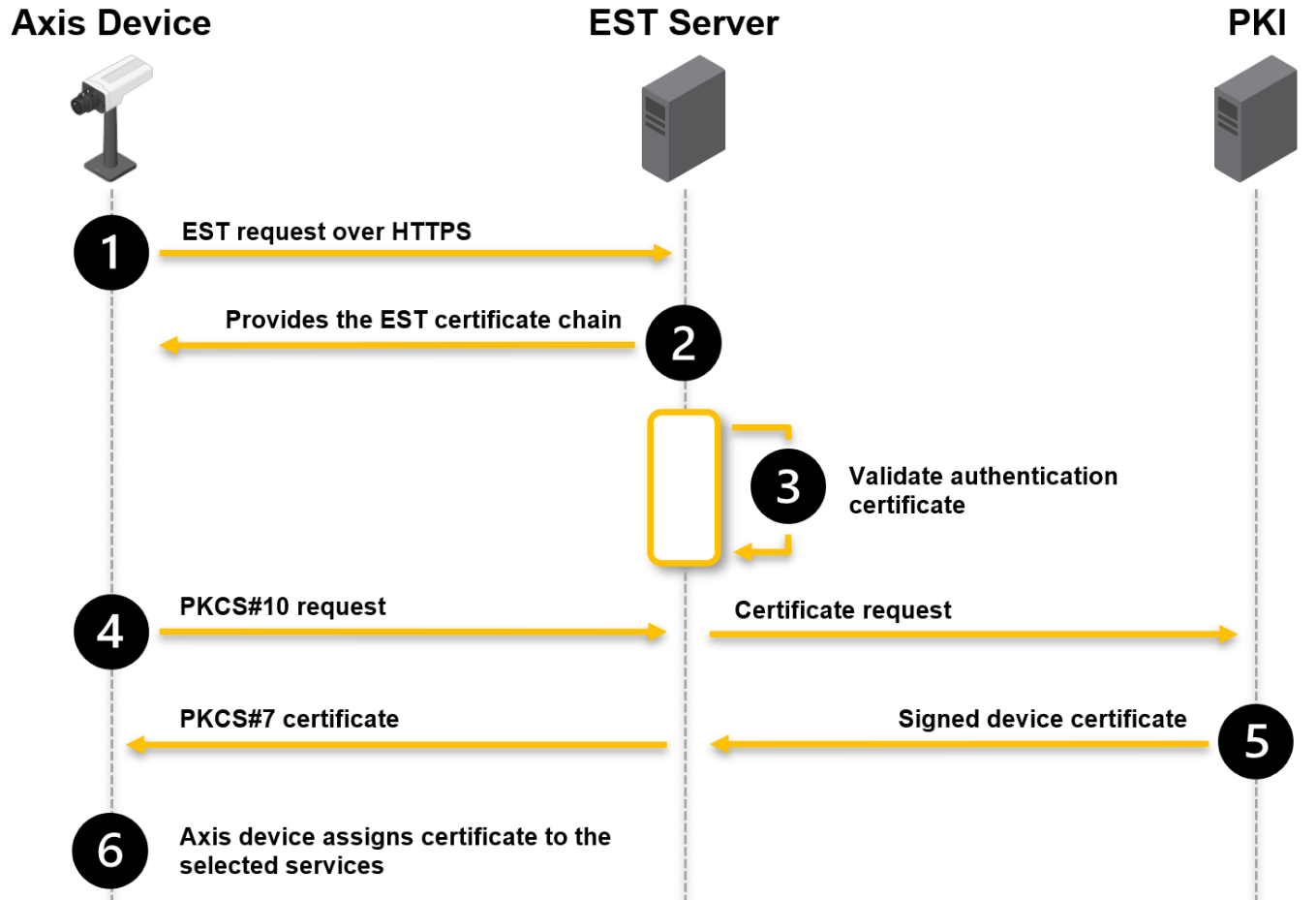
- Secure connection: the device sends an EST request over HTTPS to the EST server and establishes a secure encrypted channel. For this, the device must trust the server’s HTTPS certificate.
- Certificate chain provisioning: the EST server provides the EST certificate chain. This is only done in case the EST certificate chain is not present yet on the device.
- Device authentication: the EST server validates the device’s authentication certificate.
- Certificate request/issuance: the device generates a PKCS#10 certificate signing request and sends it to the EST server. The EST server forwards the request to the PKI, which issues the device certificate based on the configured policy.
- Certificate delivery: the EST server delivers the issued certificate back to the device using PKCS#7 format.
- Server assignment: the device assigns the issued certificate automatically to services such as HTTPS, 802.1x, MQTT and others.
Note that in some implementations, the EST server and the PKI functions may be combined for simplicity.
Axis device configuration
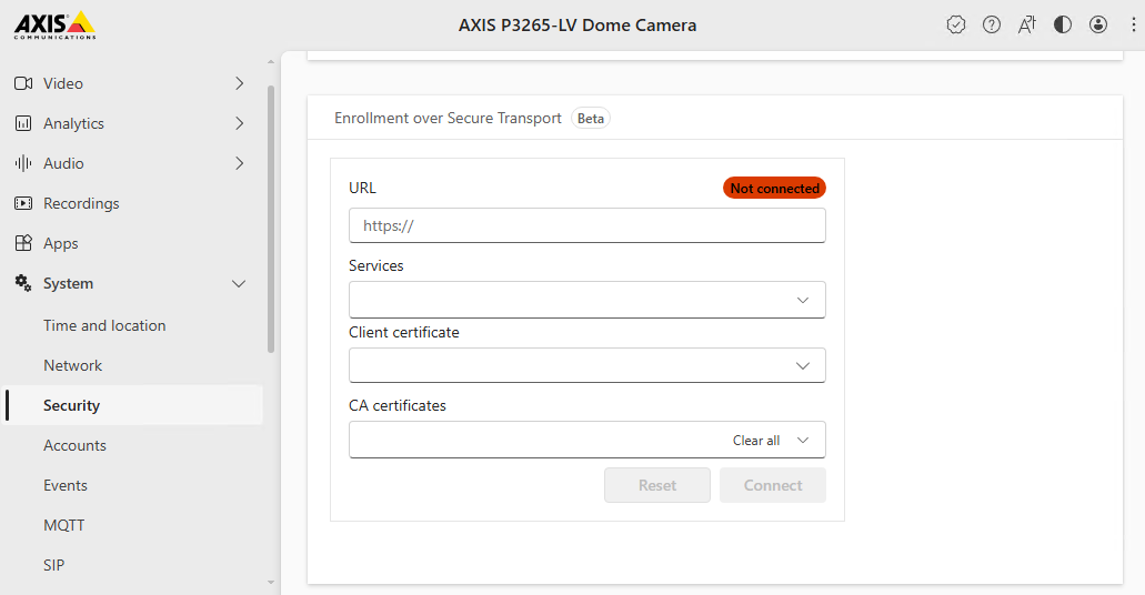
To use EST on your device, go to System > Security and configure the following:
| Parameter | Value |
URL | The server URL is defined using a well-known URI:
|
Services | Select the services that should automatically be configured with the enrolled certificate. |
Client certificate | Select a client certificate for the authentication to the EST server. The EST server needs to trust this certificate for certificate enrollment. |
CA certificates | Select the CA certificates from the EST server HTTPS endpoint so the Axis device trusts the configured EST server. |
Certificate renewal
The Axis device will attempt to renew the certificate halfway through its period of validity. This early renewal reduces the risk of service disruption if a renewal attempt fails. The device retries the renewal once per day until it succeeds.
EST configuration status
Not connected: The EST configuration has not been done or the Axis device was not able to reach or trust the configured EST server.
Connected: The Axis device was able to reach the configured EST server and has downloaded the EST certificate chain.
Enrolled: A certificate has successfully been enrolled and assigned to the selected services. In the future, the certificate will be automatically renewed according to the configured policy on the EST server.
Web interface
Browser support
AXIS OS 7.10 and higher
Video products with AXIS OS 7.10 or higher include the new web interface, which comes with an overall improved and simplified graphical user interface and focuses on camera installation, configuration, and troubleshooting. The web interface is tested and optimized for chromium browsers. It is platform-independent and works with Windows® (versions 7 and up) as well as Linux® and macOS®. If you use other browsers, you could experience limitations in functionality and support. You can find more information about the latest AXIS OS version of your Axis product here.
You can use the device with the following browsers:
ChromeTM | EdgeTM | Firefox® | Safari® | |
Windows® | ✓ | ✓ | * | * |
macOS® | ✓ | ✓ | * | * |
Linux® | ✓ | ✓ | * | * |
Other operating systems | * | * | * | * |
✓: Recommended
*: Supported with limitations
To find out more about how to use the device, see the user manual available at axis.com.
- Known limitations
No support for H.264 video streaming in Apple mobile (iOS) devices.
Audio: No support for sending audio to the camera through the browser (i.e. through a computer microphone).
Video: Some browser plugins are known to cause problems with live streaming. Try uninstalling plugins if the video does not play as it should.
Video: H.265 video streaming is currently not supported in any browser.
Firefox: You might experience issues streaming live video with audio enabled. Refresh the stream if it freezes.
Safari (macOS): You might experience issues with H.264 streaming. Refresh the stream if it freezes.
AV1 support is limited to certain products.
Depending on your macOS or iOS version, you might encounter additional login prompts when using the web interface on AXIS OS versions earlier than 10.12.
On some Linux systems, you might experience flickering when you use MJPEG. To resolve this, turn off hardware acceleration in your browser.
AXIS OS 6.5X or lower
Video products with AXIS OS 6.5X or lower are tested and optimized for the latest version of Internet Explorer*, Windows, and AXIS Media Control (AMC). Although you can use other browsers, versions and operating systems, you might experience limitations in functionality and support. You can find more information about the latest AXIS OS version of your Axis product here.
- Highlights
Recommended browser: Internet Explorer* with AXIS Media Control
Recommended for Windows operating system
- Known limitations
QuickTime player introduces a 3-second video delay when streaming
Java applet-based clients only support one-way audio, and the audio quality, as well as the frame rate, might be reduced
When using video products with AXIS OS 5.50 or lower and IE10, compatibility mode is recommended
Video streaming
AXIS Media Control and Internet Explorer* is required for video streaming H.264 over HTTP/RTSP/RTP. MJPEG video streaming is supported by Chrome, Firefox and Safari.
* Read more about Internet Explorer limitations in Internet Explorer mode in Edge.
Internet Explorer mode in Edge
Internet Explorer was previously used to view H.264 using AXIS Media Control and to configure the legacy embedded Video Motion Detection. Since Internet Explorer is outdated and unsupported, Microsoft Edge can be used for this purpose instead if set to Internet Explorer mode. Simply follow the steps below.
If using Windows 11 and the error message "Internet Explorer can’t be found. you need to re-install or re-enable Internet Explorer" appears, first follow the steps in this guide.
Go to Settings > Default browser.
Set Allow sites to be reloaded in Internet Explorer mode to "Allow".
Click "Add" next to Internet Explorer mode pages and enter the IP address of the Axis device.
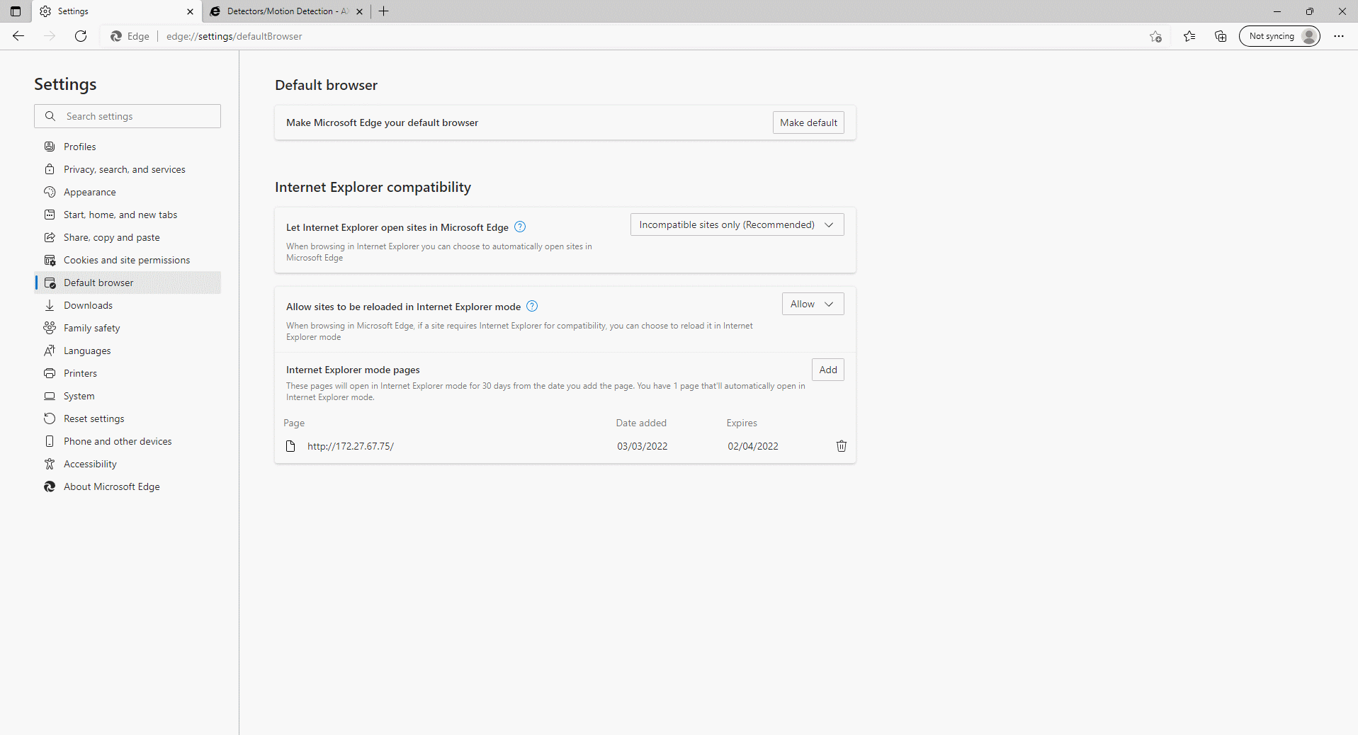
When done, Edge will work the same way as Internet Explorer for that particular device.
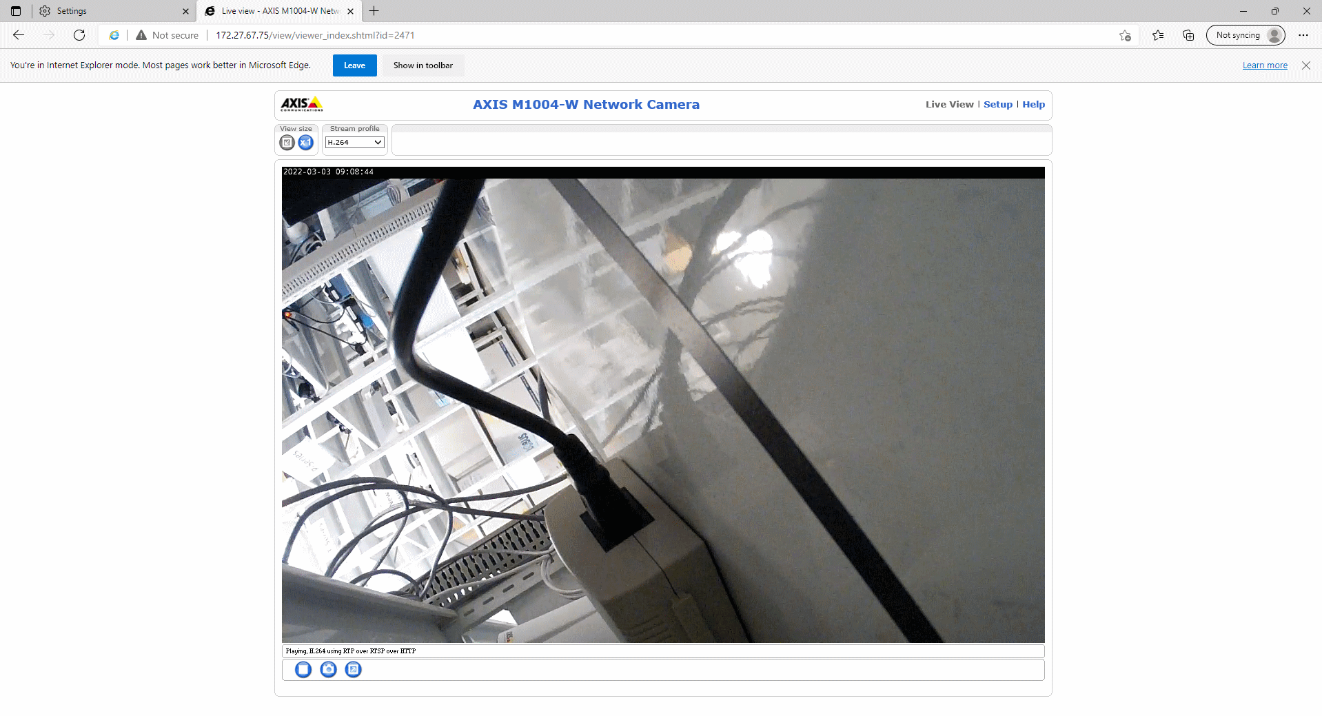
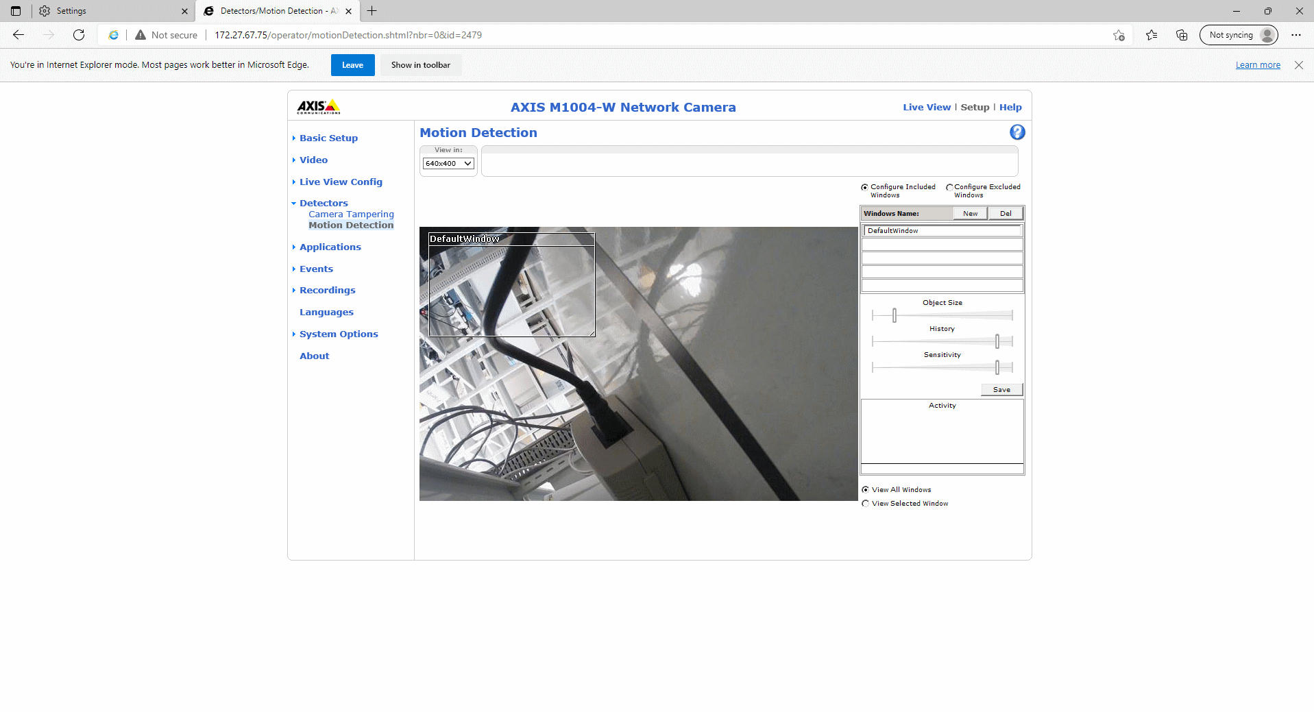
Configuration tips
Web user interface versions
When discussing various features and problems, it can sometimes be important to clarify which version of the web user interface is used. Axis devices have had several different user interfaces throughout the years.
Axis released the first network camera, AXIS Neteye 200, in 1996. The web interface in may seem quite rudimentary by today’s standards but was very much on par with everything else on the world wide web back then. (It can be noted that NCSA Mosaic, one of the first widely available and popular web browsers was released only three years prior, so Axis was in the game very early on.)
AXIS 200:

Only a couple of years later, Axis released their first encoders, or “video servers” as they were called back then; Axis 2400/2401. The web interface in these products had graphical representations of what was connected. It was also possible to control Pan-Tilt-Zoom on connected cameras directly from this web interface.
AXIS 2400:
In 1999, Axis released the first Linux based network camera, AXIS 2100. And with that, once again a brand new web interface. Unlike the gray interface in AXIS 2400/2410 that was intended for the conservative surveillance market, this interface targeted the younger web generation and thus was brighter and shinier.
AXIS 2100:
The two separate web interfaces for encoders and cameras lived side by side for a few years, but by 2003, the time had come to introduce a web interface that worked for both cameras and encoders. This interface version lived on all the way until 2016 (in different iterations) and has become what we sometime refer to as “Classic”. We will continue to refer to it as “AXIS OS web version A (Classic)”.
AXIS OS web version A (Classic)
The first version of AXIS OS web version A (Classic) was introduced in AXIS OS 4.0, but is now only supported in LTS 2016 (6.50). With the introduction of AXIS OS 7.10, this version was no longer the default interface, but it was still available via the URL http://camera-ip/index.shtml up until AXIS OS 9.20, after which it was completely removed.
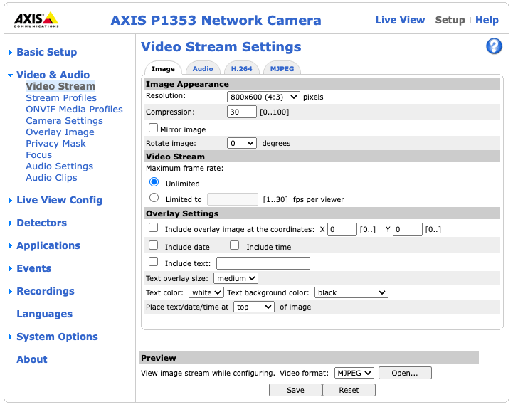
While AXIS OS web version A (Classic ) lasted for 13 years, the rest of the world wide web moved on. In 2017, it was finally time to introduce AXIS OS web version B.
AXIS OS web version B
AXIS OS web version B had a more modern look than the previous version, and also supported a much wider range of browsers (including native support for H.264 streaming). Here, focus was on the video stream, and a key feature was the possibility to actually see the video while fine tuning image settings.
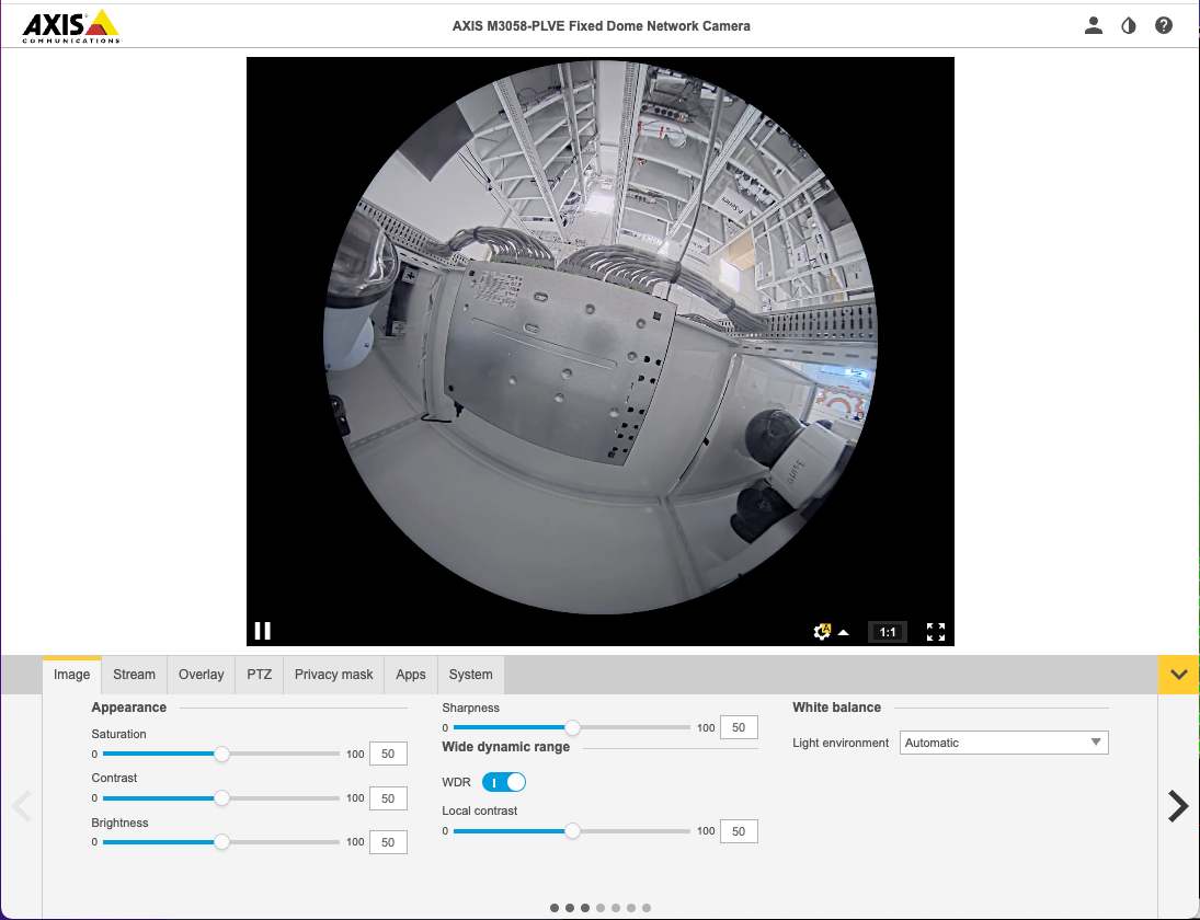
This interface was officially introduced with Axis OS 7.10, but a preview version could be seen already in AXIS OS 6.50 via the URL http://camera-ip/index.html. LTS 2018 (8.40) and LTS 2020 (9.80) both use this interface. Note that it is only intended to be used with video products.
Axis product portfolio has been growing over time and now includes many more product types than just video products. Since AXIS OS web version B only supported video products, it soon became important to create a user interface that would work for all types of products. So, in 2020, AXIS OS web version C was introduced.
AXIS OS web version C
AXIS S3008 Recorder was the first product to officially get AXIS OS web version C, which was introduced with AXIS OS 10.0.0.
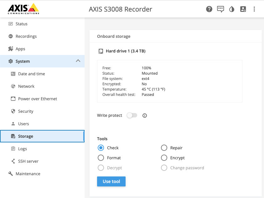
Most video products had to wait some time before officially getting AXIS OS web version C, but it could be reached through http://camera-ip/preview/index.html already in 10.0 on a selected number of products (ARTPEC-7).
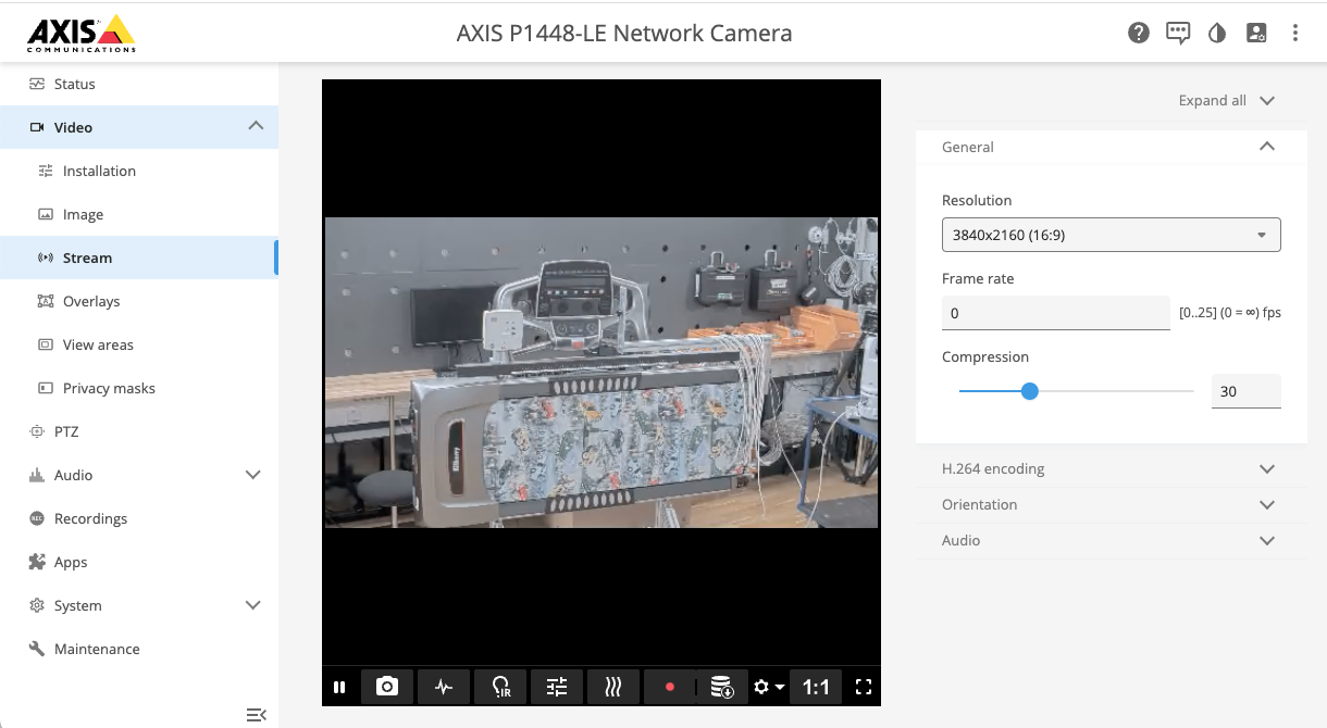
API
VAPIX
VAPIX® Network Video API is a set of Application Programming Interfaces (API) for configuration and management of Axis network video products. For more information, visit the VAPIX Library.
You can use tools like Postman or cURL to interact with the VAPIX API. cURL offers a command-line alternative for sending API requests and retrieving data, while Postman provides a user-friendly interface for sending HTTP requests and viewing responses, making it ideal for testing and exploring the VAPIX API. Both tools enable you to experiment with API calls, troubleshoot issues, and develop custom integrations.
For examples on how to use cURL, see the VAPIX Library. To learn more about VAPIX and Postman, click here.
New APIs for configuring AXIS OS devices
AXIS has released new APIs for AXIS OS configuration. These APIs were introduced in AXIS OS 11.11, and more device configuration APIs will be added on an ongoing basis. See AXIS OS demonstration video here.
Available APIs can be seen on the device itself by typing: http://IP-adress/config/discover
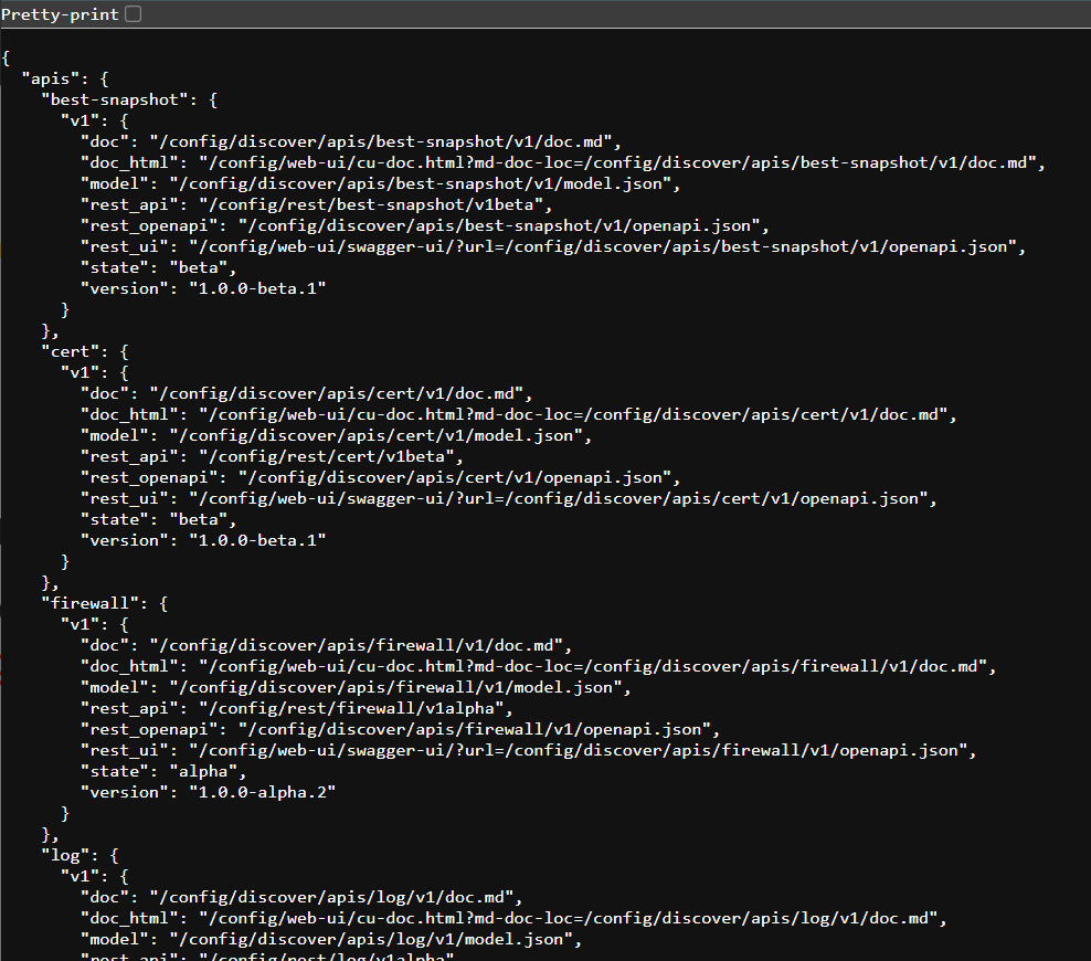
The API documentation in the VAPIX library will be delayed, but it can be found on the device itself. To see API documentation on the device write: http://IP-adress /config/web-ui/cu-doc.html?md-doc-loc=/config/discover/apis/best-snapshot/v1/doc.md
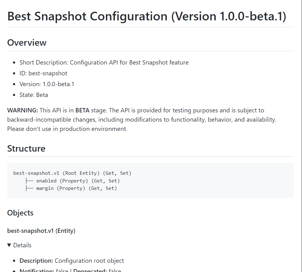
Now you get the responses from the device:
It is also possible to test the APIs through the Swagger GUI. To do this, go to the Swagger URL for the selected API, e.g. /config/web-ui/swagger-ui/?url=/config/discover/apis/best-snapshot/v1/openapi.json
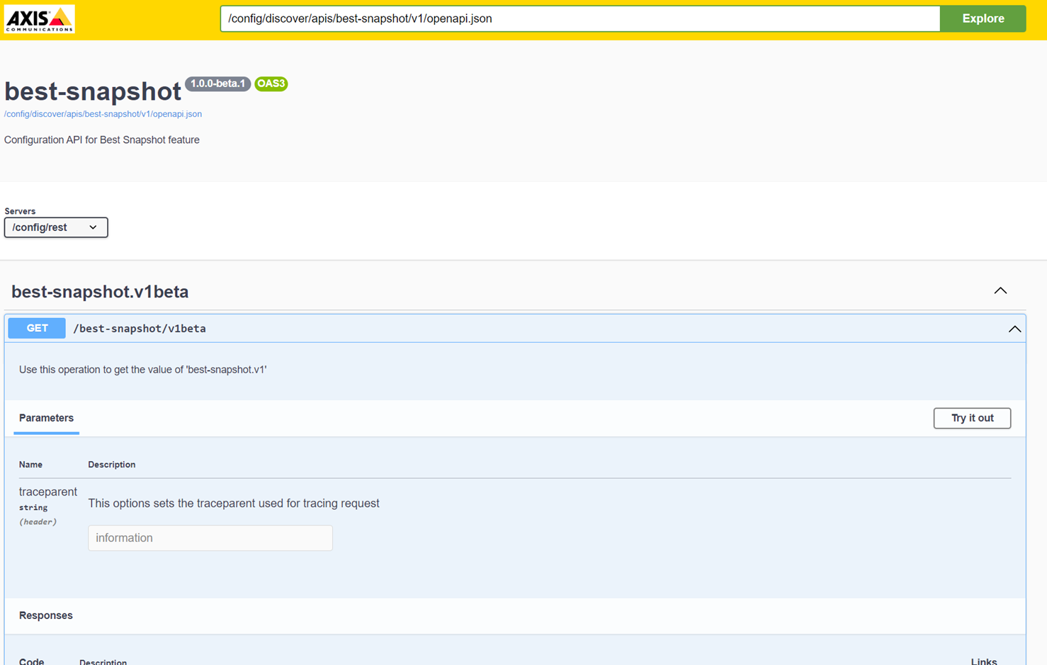
Click on Try it out button and fill in the values. Then click on the Execute button.
Now you get the responses from the device:
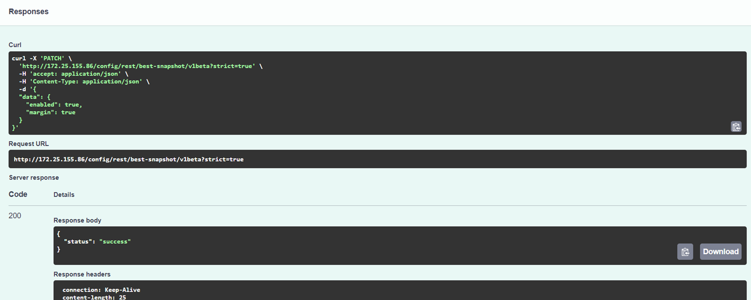
Now you can copy the code and place it to your application.
Storage & recording
Edge storage support
SD card support
The following are supported filesystems and encryptions for SD cards.
Supported filesystems: ext4 (recommended), vFAT
Supported filesystem size:
Up to 2 TB for devices with SDXC slot support and AXIS OS 5.60 and higher
Up to 64 GB for devices with SDXC slot support and AXIS OS prior to 5.60
Supported speed classes: class 10 or higher
Supported encryptions:
AES-CBC 128-bit for all devices with AXIS OS 5.80.1 and higher
AES-CBC 256-bit for all devices with AXIS OS 8.40.1 and higher
AES-XTS-Plain64 (AES-XTS-512 256-bit) for newer devices with AXIS OS 8.30.1
Network share support
The following are supported storage network protocols and authentication modes for external storage media.
Supported protocols:
CIFS/SMB 1.0 + NTLM authentication mode for devices with AXIS OS 5.90 and lower
CIFS/SMB 1.0, 2.0, 2.1, 3.0 and 3.02 + NTLM authentication mode for devices with AXIS OS 6.10 and higher
CIFS/SMB 3.1.1 + NTLM authentication mode with AXIS OS 10.12 or higher and Linux Kernel 4.17 or higher.
Supported filesystem size: 8 ZB with AXIS OS 5.70 and higher, and 2 TB with AXIS OS 5.65 and lower
Basics
Video retention
AXIS OS 6.40 and higher
There are two types of disk clean-up operations for deleting old recordings; one is user-controllable, and one is performed automatically by the Axis device.
The first operation removes recordings older than a certain time in days. This can be configured by the user in the storage configuration in the web interface. For instance, when the user selects one week (i.e. 7 days), the clean-up operation will remove all recordings older than 7 days. It's important to note that this operation runs once per hour (i.e. every 60 minutes).
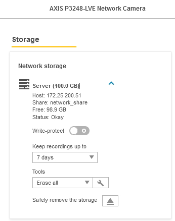
The second operation is an automatic clean-up that is always enabled and cannot be disabled by the user. This operation runs every second and checks that the network share or SD card has enough space for recording. The clean-up level is defined as an amount of free space. For locally attached storage, like SD cards, the clean-up level is defined as 5% of the total size of the SD card unless those 5% are less than 750 MB. When that is the case, 750 MB will be the clean-up level. For network shares, the clean-up level is fixed when max 750 MB remains. So for a 64 GB SD card, the clean-up level is 3.2 GB, while for an 8 TB NAS the clean-up level is 750 MB.
If there is less free space on the disk than what's defined in the clean-up level, the automatic clean-up operation will detect this and remove the oldest recordings (actually blocks) based on the needed space. Note that at least 1 GB will be removed in order to bring the free space size above the clean-up level. For instance, if the free space is 50 MB below the clean-up level, the operation will remove at least 1 GB, thus making 950 MB free above clean-up level.
If the disk is full, i.e. if the clean-up operation was not successful in removing the data on time, another level of 75 MB free space is defined. This is called the full level. If the full level is reached, the disk is declared full and the recordings should stop. At the same time, the clean-up operation continues until the free space is above the clean-up level. Once there is space above the clean-up level, recording will start again.
AXIS OS 5.50 – AXIS 6.30
In addition to the configuration that can be performed in AXIS OS 5.40 and lower, the clean-up of old recordings will start when there is less than 750 MB of storage space available. This is an additional algorithm that has been implemented to prevent exceeding the network share or SD card storage space.
AXIS OS 5.40 and lower
In AXIS OS 5.40 and lower, there are two user-controlled clean-up parameters that defines when the Axis device should be performing a clean-up of the storage. The first parameter is used to configure number of days until recordings should be overwritten, and the second parameter is a clean-up policy in percentage. Old recordings are deleted if either one or both of the conditions in these parameters are met.
It's recommended to set the clean-up policy to 80 for AXIS OS 5.20 and 90 for AXIS OS 5.40. As an example, a clean-up value of 90 corresponds to 72% usable storage, and the Axis device would then have 72 GB writable recording space when connected to a 100 GB network share. The clean-up level can be configured from Plain Config > Storage.
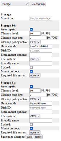
Recording file split duration
For performance reasons and optimal read/write cycles to the edge storage medium, video is recorded in chunks of five minutes. This is defined in DefaultSplitDuration = "300", where "300" refers to 300 seconds, which in turn corresponds to five minutes. Note that it’s not recommended to change the value since this could affect the memory buffers. It could also affect performance since a split duration that is too short could cause a high amount of files. If the value is changed, make sure it's tested accordingly. In AXIS Companion, it’s possible to download a part of the video merged into one file in asf format, which is the recommended way to solve this issue. From AXIS OS 5.60 and onwards, the video export feature has been improved so that it's possible to export a recording from several 5 minute segments into one recording.
ONVIF and VAPIX recordings
ONVIF and VAPIX recordings are completely separated. For example, recordings that are created via VAPIX through the web interface or VAPIX API are not visible or usable for ONVIF clients. In return, ONVIF recordings are not visible or usable for the user and are not showing in the recording section of the web interface. ONVIF clients have to create recordings through the ONVIF API separately to make use of recordings.
Metadata events
It's possible to listen to storage-related metadata events via the RTSP stream. Essentially there are two events available, both indicating a storage connection failure either for an SD card or a network share. These two events are called:
Device/HardwareFailure/StorageFailure
Storage/Disruption
If for example the network share is disconnected due to the NAS no longer being available in the network, both events would be active.
Edge storage folder structure
When performing an edge recording on an Axis device, the below folder structure is being used*. This folder structure can not be modified.
Example recording path: *\axis-ACCC8E9C6BE7\20211214\11\20211214_110037_AAF2_ACCC8E9C6BE7\20211214_11
| Network share | SD card | Example | Format | Contains |
|---|---|---|---|---|
✓ | axis-ACCC8E9C6BE7 | axis-ZZZZZZZZZZZZ | The Axis device serial number | |
✓ | ✓ | 20211214 | YYYYMMDD | Date** |
✓ | ✓ | 11 | HH | Hours** |
✓ | ✓ | 20211214_110037_AAF2_ACCC8E9C6BE7 | YYYYMMDD_HHMMSS_XXXX_ZZZZZZZZZZZZ | Date and time**, a random identifier, the Axis device serial number |
✓ | ✓ | 20211214_11 | YYYYMMDD_HH | Date and hours** |
* The "Send video" and "Send images" event options may use a different folder structure based on the configured recipient.
** The date and time reference is in the Axis device’s local time and refers to the date and time when the recording was created.
Password-encrypted export of edge recordings
As of AXIS OS 10.10, Axis devices support the password-encrypted export of edge recordings (SD cards, network shares), as well as recordings made on AXIS OS-based recorders. This means it’s possible to export a recording that is password-encrypted, so you can securely share sensitive video data without having to manually encrypt recordings.
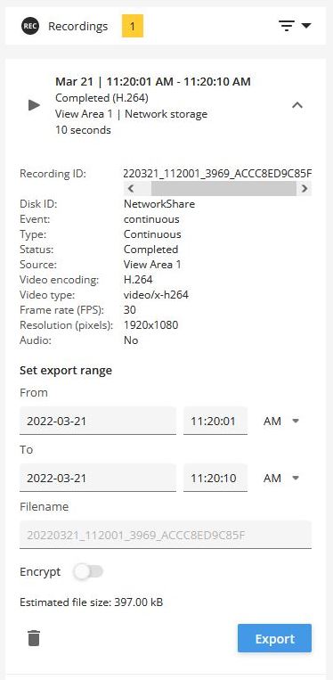 | 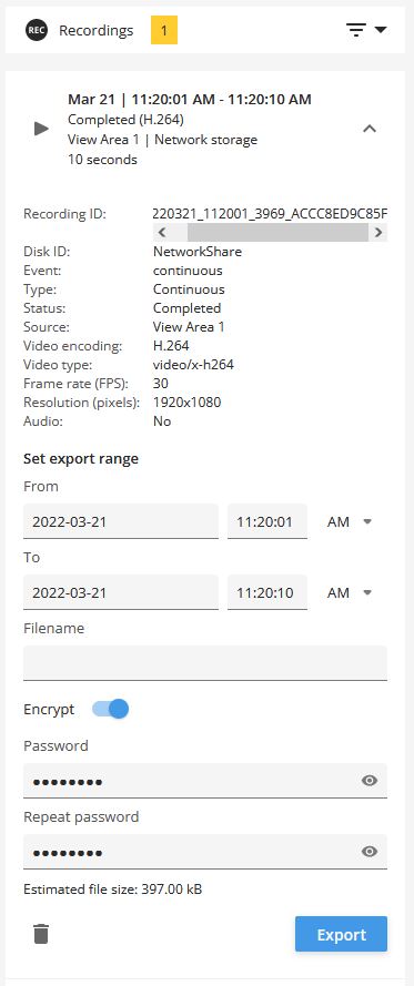 |
Password encrypted recordings
Supported file format: *.zip
Supported password length: maximum 128 bytes (128 characters). In the legacy web interface the maximum is 64 characters.
Supported encryption: AES-256. Note that some operating systems do not have native support for this encryption. In those cases open-source tools such as 7-zip can be used to open password encrypted recordings.
Export file name
The file name of regular recording exports may contain sensitive information such as the date and time or the camera name. When doing a password encrypted export of a recording, leave the file name field empty and the file name of both the downloaded *.zip file and content names will get anonymized.
| Example of a regular recording export | 20220321_112001_3969_ACCC8ED9C85F.zip |
| Example of a password encrypted export | FBHY6A.zip |
SD card
Disabling the SD card
The SD card and its slot can be disabled completely. This is done from Plain Config > Storage > Storage.S0.Disabled. When the SD card slot is disabled, the Axis device will not recognize any SD card inserted.
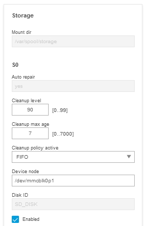
SD card health monitoring
From AXIS OS 6.20, Axis devices support health statistics for AXIS Surveillance Cards. This means it's possible to get an estimated wear out level for the SD card being used, which can help determine when to replace it.
Only available for AXIS Surveillance Cards, not for similar cards from the same manufacturer.
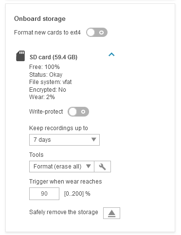
From AXIS OS 10.3, it's possible to create an event based on the wear level of the SD card so that you can get notifications when a certain wear level is reached. More information is available in this video:
Decrypting Axis SD cards
We will now take a look at how an encrypted SD card operated in an Axis device can be decrypted or re-used again.
The original passphrase (password) that was used to encrypt the SD card must be known in order to proceed with any of the guidelines below.
Axis device
An SD card that was encrypted and previously used in an Axis device can be inserted and used in another Axis device again. This could e.g. happen when an Axis device gets replaced during an RMA process.
Windows
To decrypt an SD card on a Windows computer, an open-source disk encryption tool like LibreCrypt can be used.
If the SD card is formatted to VFAT, follow the screenshot guide below. If EXT4 is used, you need to install a third-party driver like Ext2Fsd first in order for the Windows computer to recognize the filesystem on the card.
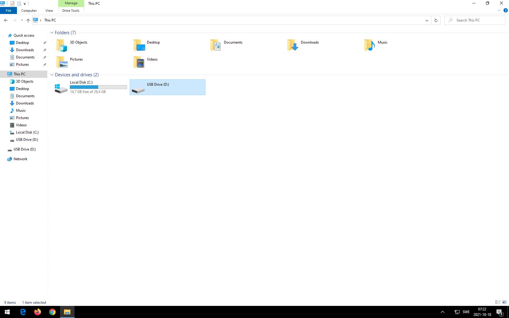
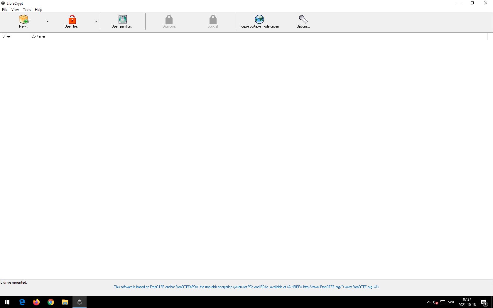
Linux
In Linux operating systems, the SD card can be decrypted directly using the command line and the following commands:
sudo cryptsetup open /dev/sdf1 qqq
Enter passphrase for /dev/sdf1:
mkdir /tmp/qq ~
sudo mount /dev/mapper/qqq /tmp/qq
sudo su
cd /tmp/qq
root@mycomputer:/tmp/qq# ls
20160929 index.db lost+found
root@mycomputer:/tmp/qq# exit
sudo umount /tmp/qq
sudo cryptsetup close qqq
Formatting Axis SD cards
Formatting the SD card will only rewrite the parts of the SD card necessary to create the filesystem. This could be a couple of hundred MBs on a 64 GB SD card. Any of the old data, such as older recordings, will not be accessible via the new filesystem. However, a major part of the SD card data will be unmodified after formatting and may thus be accessible on a low level (i.e., it may be possible to extract the data if the card is inserted in a computer).
There are various methods to erase sensitive data on SD cards and they usually require writing the entire card with different patterns multiple times. Axis products do not have support for erasing data in such a way.
Network share
SMB/CIFS handshake
Here we'll take a closer look at the differences and negotiations in the SMB/CIFS protocol. The network traces in the table illustrate the process of negotiating a specific SMB version between an Axis device and a NAS and the corresponding session setup in order to mount a network share successfully. After the negotiating process is completed, we can observe some regular SMB protocol communication about listing, deleting and writing files to the network share.
| Example network trace | SMB version | SMB dialect | NAS IP address | Axis device IP address |
| Axis_SMB_Handshake_SMB_1.0.pcapng | 1.0 | NT LM 0.12 | 172.25.200.50 | 172.25.201.100 |
| Axis_SMB_Handshake_SMB_2.0.pcapng | 2.0 | SMB 2.02 (0x0202) | 172.25.200.50 | 172.25.201.100 |
| Axis_SMB_Handshake_SMB_2.1.pcapng | 2.1 | SMB 2.1 (0x0210) | 172.25.200.50 | 172.25.201.100 |
| Axis_SMB_Handshake_SMB_3.0.pcapng | 3.0 | SMB 3.0 (0x0300) | 172.25.200.50 | 172.25.201.100 |
| Axis_SMB_Handshake_SMB_3.02.pcapng | 3.02 | SMB 3.0.2 (0x0302) | 172.25.200.50 | 172.25.201.100 |
| Axis_SMB_Handshake_SMB_Auto.pcapng | Auto-negotiated | N/A | 172.25.200.50 | 172.25.201.100 |
About CIFS/SMB support
SMB support in Axis devices
| AXIS OS version | 12.00 and higher | 8.30 – 11.90 | 6.10 — 8.20 | 5.90 and lower |
| Enabled | SMB 2.1, 3.0, 3.02, 3.1.1 | SMB 2.1, 3.0, 3.02, 3.1.1 | SMB 1.0 | SMB 1.0 |
| Supported | SMB 2.1, 3.0, 3.02, 3.1.1 | SMB 1.0, 2.0 2.1, 3.0, 3.02, 3.1.1 | SMB 1.0, 2.0 2.1, 3.0, 3.02, 3.1.1 | SMB 1.0 |
| Auto-negotiation | Yes | Yes | N/A | N/A |
AXIS OS 8.30 and higher
In Axis devices with AXIS OS 8.30 to 11.9, the insecure versions SMB 1.0 and SMB 2.0 are disabled per default in order to increase the overall minimum cybersecurity level of the device. Devices with AXIS OS 12 and higher only support secure versions of the SMB protocol.
It’s possible for the device to auto-negotiate its SMB version with the NAS or edge storage device starting with SMB 2.1, or with higher SMB versions such as SMB 3.0, SMB 3.02 and SMB 3.1.1.
AXIS OS 8.20 and lower
In Axis devices with AXIS OS 8.20.1 and lower, SMB 1.0 is enabled per default while all other supported SMB versions (SMB 2.0, 2.1, 3.0, 3.02) need to be set in Plain config as described below.
Setting SMB version in Plain config
If SMB 1.0 or SMB 2.0 is required due to compatibility issues, we recommend setting the extra mount options parameter in Settings > System > Plain config > Storage to a specific version, e.g. vers=1.0 or vers=2.0 for a network share. Note that there are two storage groups per mounted network share (normally Storage S1 and Storage S2), and both need to have the correct version set in extra mount options. If the setup also includes a network share recipient, then this recipient would be included in the S3 or S4 storage group and would also need modification. See the following example of how the configuration should look like when the NAS storage only supports SMB 1.0:
http://ip-address/axis-cgi/admin/param.cgi?action=update&root.Storage.S1.ExtraMountOptions=vers=1.0
http://ip-address/axis-cgi/admin/param.cgi?action=update&root.Storage.S2.ExtraMountOptions=vers=1.0
Extra mount options
Below you will find three configuration examples describing how the device is handling the extra mount options parameter. As you can see, the device will only consider the latter of the two SMB versions entered. Preferably only a single SMB version should be entered.
vers=1.0: device tries to connect via SMB 1.0
vers=1.0,vers=2.0: device tries to connect via SMB 2.0
vers=1.0,vers=2.0,sec=ntlm: device tries to connect via 2.0 SMB with NTLM only
seal,sec=ntlmsspi: Highest security, password hashing encapsulated in Raw NTLMSSP message, force packet signing and encryption
Automatic reconnection
In case the NAS is disconnected from the network, the Axis device will try to automatically remount a network share. A prerequisite for trying to remount a network share is that the NAS is online/available on the network, e.g. via PING. The first attempt to remount the network share will be executed after 2 seconds, and every failed attempt will double the time between new intervals:
First try: executed after 2 seconds
Second try: executed after 4 seconds
Third try: executed after 8 seconds
This will continue until the last try, which will be executed after 600 seconds (10 minutes).
Network share in Plain Config
In the storage section in Plain Config, the complete storage configuration can be obtained from an Axis device. The storage section is splitted into S0-S2 storage groups, where S0 corresponds to the SD card configuration, and S1 and S2 are the network share configuration equivalents.
When mounting a network share on the Axis device, two storage groups - S1 and S2 - are created. S1 is the physical network share and its disk, while S2 is the network share recipient that e.g. could be used in the event system of the Axis device.
Cloud storage
Here’s how to set up recording to cloud platforms like AWS S3 and Azure Blob Storage:
Available in AXIS OS 11.11 and later.
Set up your S3 or Azure server and create a bucket for the recordings. Then, create a destination on your device by providing the required parameters:
id (the ID of the destination, which isn't part of the S3 or Azure parameters)
accessKeyId
bucket
secretAccessKey
sessionToken (optional)
url (the URL to the S3 or Azure server)
- Here’s an example of what the data might look like:
Create a recording group using the new recording group API. You’ll need to provide the destination ID as a required parameter. You can do this by sending a request to:
http://<target_ip>/config/rest/recording-group/v2/recordingGroupsStart a recording using the same group.
{"id": "my_s3_dest", "s3": {"accessKeyId": "minioadmin", "bucket": "test-bucket", "secretAccessKey": "minioadmin", "sessionToken": "session_token", "url": "http://172.27.140.1:9000"}}If you need help finding the APIs, you can use the discover feature: http://<camera_IP>/config/discover.
You can also use the Swagger UI pages for the APIs to set up your destination and group quickly. You can find these at http://<camera_IP>/config/web-ui/swagger-ui/?url=/config/discover/apis/remote-object-storage/v1/openapi.json and http://<camera_IP>/config/web-ui/swagger-ui/?url=/config/discover/apis/recording-group/v2/openapi.json.
Best practices
Below you'll find some guidelines for setting up edge recording on your Axis device.
Use H.264 to reduce bandwidth and avoid MJPEG streams.
Use only one recording at a time when recording to an SD card to avoid shortening the SD card's lifespan and minimizing its wear level.
When configuring your recordings, add at least 30 seconds of post-buffer recording to each event triggered recording in order to avoid many small recording segments
Configure the Axis device properly with the correct date & time prior to starting a recording. Date & time can either be configured manually or automatically via the NTP server.
Check with the NAS-vendor if the amount of (video) data can be processed by the NAS in order to avoid performance issues.
Keep the bitrate of the video stream below 10 Mbit/s when recording to the SD card in order to avoid missing frames/recordings.
On Axis devices with a legacy version, set the clean-up level (i.e. the limit when older recordings are erased) to max 80% on AXIS OS 5.20 and 90% on AXIS OS 5.40.
Timelapse recordings
There are several ways to configure timelapse recordings in Axis products. Below you will find more information and examples of different configuration setups.
A workaround previously described as saving images to the SD card using FTP and the IP address of the device itself is not supported by Axis. The configuration in question has been made unavailable in later AXIS OS versions. It’s recommended to use one of the following alternatives instead.
Recording to SD card using third-party ACAP solutions
Axis recommends third-party solutions such as Timelapse Server and Timelapse video developed by Pandos Development (https://pandosme.github.io/). Some of the features these solutions offer include:
Timelapse recordings to SD card or network share
Ability to download the AVI-video directly from the ACAP with user-selectable frame rate and playback rate
Several different timelapse recordings supported simultaneously
Alert notification in case a timelapse recording has issues
Depending on your Axis device and architecture, the Timelapse Me ACAP comes in three different application filetypes (mips, armv7hf or aarch64). Use the following VAPIX request http://ip-address/axis-cgi/param.cgi?action=list&group=Properties.System.Architecture to find out which architecture is supported by your Axis device, and select the correct application filetype and upload it to your Axis device.
Recording to remote host using FTP server
Use FTP properly as it is a standard network protocol to transfer files from one host to another over the internet. Upload to a remote host, e.g., another computer or server on the network with a static path.
Example configuration in web interface in AXIS OS 6.53 and lower
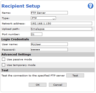 |  | 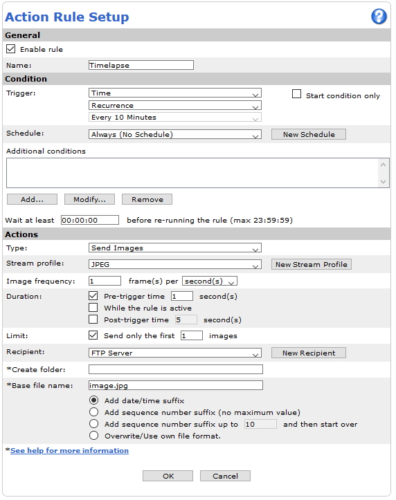 |
Example configuration in web interface in AXIS OS 9.30 and higher
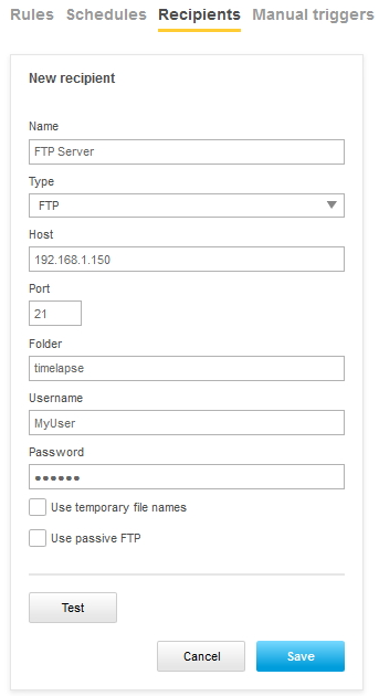 |  | 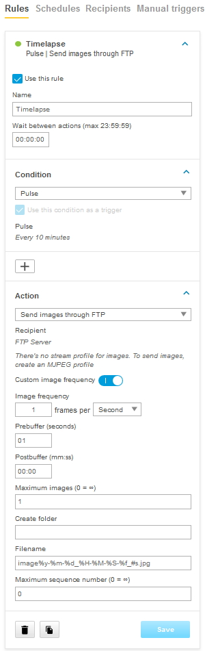 |
Recording to remote host using network share
Example configuration in web interface in AXIS OS 6.53 and lower
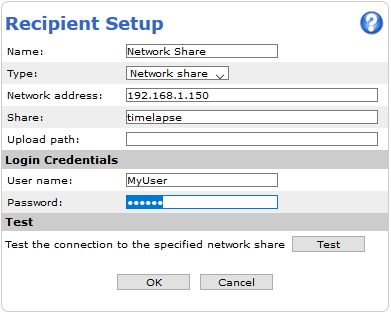 |  | 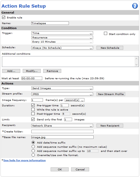 |
Example configuration in web interface in AXIS OS 9.30 and higher
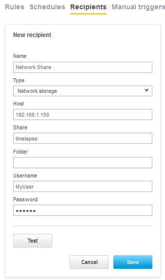 |  | 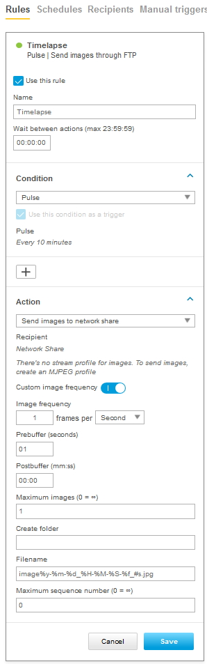 |
Recording to remote host using mail
Example configuration in web interface in AXIS OS 6.53 and lower
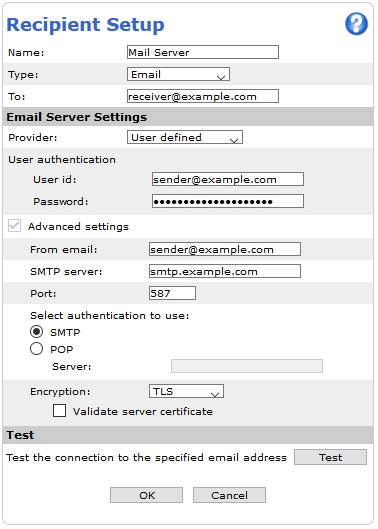 | 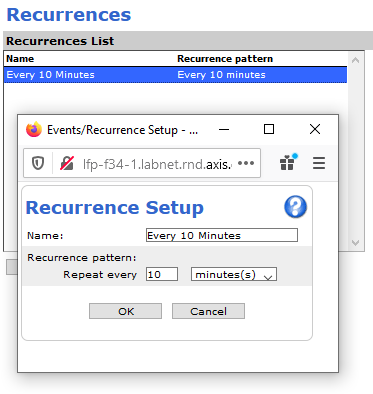 | 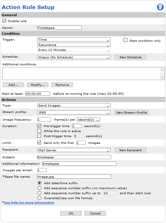 |
Example configuration in web interface in AXIS OS 9.30 and higher
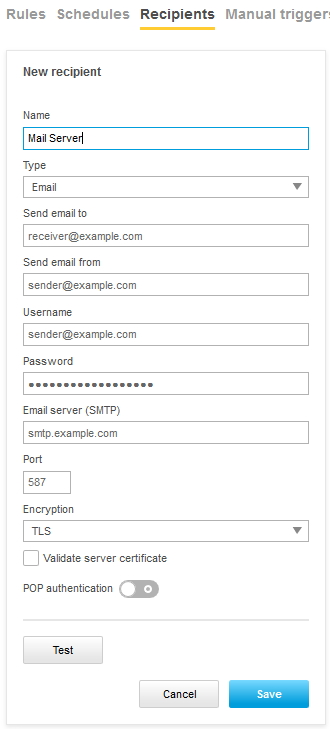 | 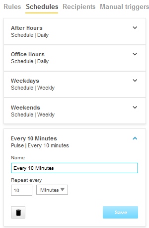 | 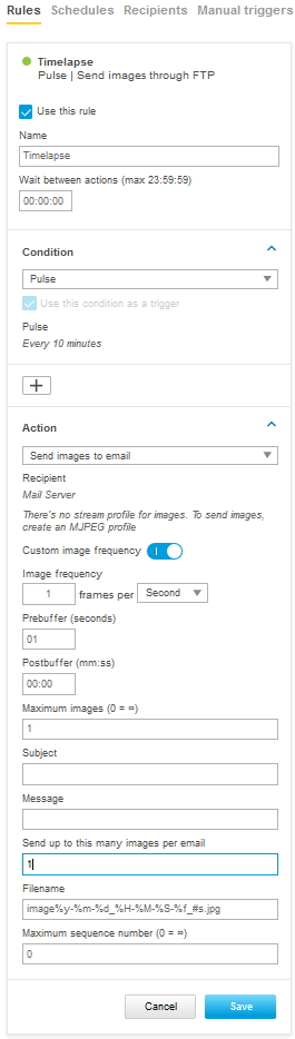 |
Troubleshooting & maintenance
Export-import device configuration
In AXIS OS 12.4 we introduced the export-import device configuration feature in AXIS OS-based devices.
This feature significantly streamlines the process of configuring multiple devices. By initially logging in to a single device and performing the necessary configurations, you can then export these settings to a JSON file. This file can then be modified to create a standardized configuration template, which can be seamlessly imported via the web interface to configure the other devices.
This feature provides great benefits for various use cases, including:
Multi-device configuration: When deploying multiple devices, export-import configuration saves time and ensures consistency across all devices.
Configuration template creation: Exporting configurations allows administrators to create standardized templates for the same device types, or to combine common settings for different devices in a single template.
Backup: Configuration backups provide a record of changes made to devices after each AXIS OS upgrade.
Device replacement after RMA: When replacing a faulty device, restoring the previous configuration ensures minimal disruption to operations and maintains existing settings.
Troubleshooting: Restoring a previous configuration can help troubleshoot issues by reverting to a known working state.
This feature is still in the beta stage in AXIS OS 12.4 and is not activated by default. To use it, go to System > Plain config > Feature flags and enable DeCAF export import.
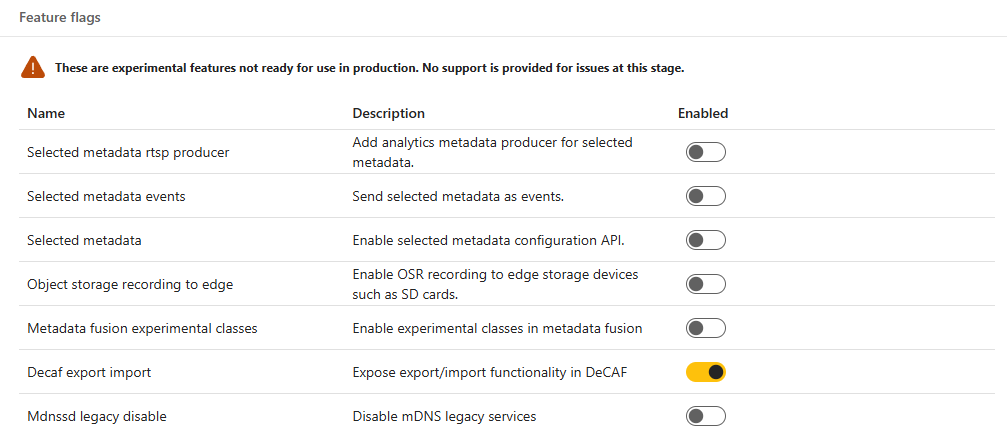
Then go to Maintenance > Device settings. Refresh the page if it doesn’t appear.
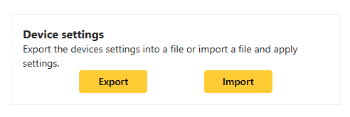
The Export feature lets you download the current device configurations to a JSON file with a single click of a button. You can edit this file with a text editor, add new configuration values, remove existing ones, or alter the existing settings as required. The Import feature enables the efficient deployment of customized settings by parsing the JSON configuration file, thus simplifying the implementation of desired configurations and enhancing overall system administration.
Below are the APIs supported in this feature, based on the AXIS OS versions:
| AXIS OS version | APIs |
| 12.4 | param.cgi New Time API under device configuration |
| 12.7 | Action rules and recipients |
| 12.8 | Schedules |
When exporting the configuration, ALL the readable parameters associated with the aforementioned APIs are exported. After the file is exported, you can make modifications to it by editing it directly. When importing the configuration file, the device verifies it before applying it. Any parameters incompatible with the device are automatically ignored and excluded from the import process, ensuring a seamless and error-free configuration update. Also, some APIs may require a set of valid parameters in order to apply a proper configuration. The legacy param.cgi parameters don’t have this control functionality.
This feature is based on the device configuration framework. In the future, all newly introduced APIs will be implemented under the same framework and will have export-import functionality. The current implementation does not include the Events and ACAP configurations.
How to upgrade
Axis offers product AXIS OS management according to the active track or the long-term support (LTS) tracks. Regardless of the track chosen, it’s recommended to upgrade regularly in order to get the latest security updates. Upgraded can be done by using AXIS Device Manager, AXIS Camera Station, AXIS Companion or HTTP.
- AXIS A1001 in cluster mode: If using AXIS A1001 in cluster mode, make sure to upgrade all controllers. Either all at a time using AXIS Device Manager or straight after each other using the web interface or FTP. The entire cluster should always be on the same version.
- Mandatory upgrade path (10.9): The following Axis devices require an upgrade via the latest available LTS 2018 (8.40) prior to upgrading to AXIS OS 10.9 or later: AXIS D2050-VE, AXIS FA54, AXIS M3057-PLVE, AXIS M3058-PLVE, AXIS P1367/-E, AXIS P1368-E, AXIS P1445-LE, AXIS P1445-LE-3, AXIS P1447-LE, AXIS P1448-LE, AXIS P3227-LV/-LVE, AXIS P3228-LV/-LVE, AXIS P3807-PVE, AXIS Q1645/-LE, AXIS Q1647/-LE, AXIS Q1659, AXIS Q3515-LV/-LVE, AXIS Q3517-LV/-LVE/-SLVE, D101-A XF P3807, ExCam XF P1367, ExCam XF Q1645 and F101-A XF P1367.
- Axis Edge Vault (10.11): From AXIS OS 10.11 and onwards, Axis Edge Vault will be upgraded automatically during an upgrade of the Axis device. The upgrade functionality introduces a non-backward compatible change to the behavior of Axis Edge Vault. The upgrade process is not reversible: once Axis Edge Vault has been upgraded, it cannot be downgraded. Installing an older release of AXIS OS on a device where Axis Edge Vault has been upgraded is highly discouraged. Core functionality such as HTTPS, 802.1x, and applications that are configured through the certificate management system will not work correctly. It is recommended to first upgrade through AXIS OS 10.10 and then to newer AXIS OS versions. This way, if the upgrade process fails or a rollback is triggered, the device will still be left with an AXIS OS system that is compatible with an upgraded Axis Edge Vault.
AXIS Device Manager or AXIS Camera Station
Go to the Device Manager Tab in Axis Device Manager or Configuration Tab > Devices - Management in AXIS Camera Station.
Select all devices that should be upgraded.
Right click and select Upgrade Firmware, which will open a dialog with a list of device models and the current firmware version installed in each device.
In the Upgrade Firmware dialog there are two options:
Check for Updates which requires internet access.
Browse to locate the file e.g. on hard drive or memory stick.
Check for updates:
Select Check for Updates to download a list of all versions available for all device models.
Browse:
Select browse to locate the files and import them. It is possible to select and import several files at the same time.
Each device model will show a dropdown containing all available versions for a model, sorted by “Long Term Support” (LTS) and “Active” software tracks.
Select the version to install for each device model.
Click OK to start upgrading the devices.
By default, upgrade is done for all the selected devices at the same time. The upgrade order can be changed in Configuration > Connected services > Firmware upgrade settings. Once an update has been started, the devices will be unavailable until the installation and restart of the devices has completed successfully.
For more information, see the help in AXIS Device Manager/AXIS Camera Station.
HTTP
Upgrade instructions when using the old web interface
Download the upgrade file to a directory that is accessible from your local computer.
Open the product's start page (e.g.
http://192.168.0.90) in a web browser.Click the Setup link and log in as "root" (or any other user with administrator privileges). You must be logged in as an administrator to upgrade the unit.
Click System Options in the menu to the left.
Click Maintenance.
Click the Browse button in the Upgrade Server section.
Select the upgrade file you downloaded (and maybe decompressed) from our site. This file is typically named after the product and AXIS OS version.
Click the Open button.
Click the Upgrade button in the Upgrade Server section.
Wait for the flash load to complete, which may take 1-10 minutes. The upgrade procedure occurs in four steps:
Step 1: Shut down. Running applications are shut down and active connections are terminated.
Step 2: Uploading. The old version will be erased and the new will be saved. During this step, the power LED will blink green/amber. After a while the progress of the upgrade will be displayed in the web browser.
Step 3: Reboot. The system restarts automatically.
Step 4: Reconfiguration. The new versions settings are configured to match the previous settings. The color of the status LED will be amber during this step.
After the upgrade has completed, the unit will automatically initiate the system, during which the status LED blinks amber. When initiation is complete and the system is ready for use, the status LED will be green.
Upgrade instructions when using the new web interface
Download the upgrade file to a directory that is accessible from your local computer.
Open the product's start page (e.g.
http://192.168.0.90) in a web browser.Log in as "root" (or any other user with administrator privileges).
Click Settings to the right.
Click System-tab.
Click Maintenance.
Select the upgrade file you downloaded (and maybe decompressed) from our site. This file is typically named after the product and AXIS OS version.
Click the Open button.
Click the Upgrade button in the Upgrade Server section.
Wait for the flash load to complete, which may take 1-10 minutes. The upgrade procedure occurs in four steps:
Step 1: Shut down. Running applications are shut down and active connections are terminated.
Step 2: Uploading. The old version will be erased and the new will be saved. During this step, the power LED will blink green/amber. After a while the progress of the upgrade will be displayed in the web browser.
Step 3: Reboot. The system restarts automatically.
Step 4: Reconfiguration. The new versions settings are configured to match the previous settings. The color of the status LED will be amber during this step.
After the upgrade has completed, the unit will automatically initiate the system, during which the status LED blinks amber. When initiation is complete and the system is ready for use, the status LED will be green.
FTP
- Only applicable for AXIS OS versions 11.0 and below. With AXIS OS 11.1 and later, the FTP options has been removed to increase overall minimum cybersecurity level. For more information, visit SSH access.
- With AXIS OS 7.30.1 - 11.0, the FTP server is disabled by default. In order to use the instructions below it first needs to be enabled via the web interface: Settings > System > Plain config > Network > NetworkFTP
- This section is not applicable for AXIS Companion Line cameras.
You must be at the command prompt and in the directory that contains the upgrade file.
Example:
C:\Axis\Product\FirmwareFrom the command prompt, open an FTP connection to the unit you wish to upgrade.
(Do not use a Windows based FTP program to do this, use command line FTP programs only.)Log in as “root”. You must be logged in as the root user to upgrade the unit.
Change to binary transfer mode by typing "bin" and press enter.
Type "hash" and press enter. This will allow you to see how the upgrade progresses.
Type the command "put XXX.bin flash" where XXX.bin is the name of the upgrade file you downloaded (and maybe decompressed) from our site. This file is typically named after the product and AXIS OS version.
Wait for the flash load to complete, which may take 1-10 minutes. The upgrade procedure occurs in four steps:
Step 1: Shut down. Running applications are shut down and active connections are terminated.
Step 2: Uploading. The old version will be erased and the new will be saved. During this step, the power LED will blink green/amber. After a while, the progress of the upgrade will be displayed in the command prompt.
Step 3: Reboot. The FTP session terminates and the system starts automatically.
Step 4: Reconfiguration. The new versions settings are configured to match the previous settings. The color of the status LED will be amber during this step.
After the upgrade has completed, the unit will automatically initiate the system, during which the status LED blinks amber. When initiation is complete and the system is ready for use, the color of the status LED will be green.
How to downgrade
Downgrading an Axis product might be necessary in order to establish compatibility with the third party systems which do not support higher AXIS OS versions. The downgrade is performed in the same way as an upgrade. Instructions are available in How to upgrade.
If you have a device that has received a new hardware id (HWID), check the Hardware changes section to see the minimum compatible AXIS OS active and LTS versions for the product.
Downgrading to a lower version could cause implications on a system’s health and stability. It is only recommended to downgrade an Axis product using the standard upgrade process if performed in combination with a factory default of the product. The factory default can be performed simultaneously during the downgrade, or manually by the user afterwards.
As of AXIS OS version 10.1, a factory default is mandatory when downgrading.
How to rollback
When upgrading an Axis product, a restore point of the previous state of the product and its entire configuration is made before the upgrade. This restore point is available to go back to after the upgrade has been performed in case of an unexpected issue. This feature is called Rollback.
The rollback feature can be found in the Axis product’s web interface under Settings > System > Maintenance. A video clip with instructions can also be found in Configuration tips. The feature was introduced in AXIS OS version 7.40, which means that the Axis product must have been upgraded to 7.40 or later in order to be able to perform a rollback.
It is recommended to use the rollback function to re-establish system functionality and to contact Axis Technical Support for further instructions and troubleshooting techniques. No restore point is available when the product is in a factory defaulted state.
Factory default and restore
When troubleshooting or preparing your device for redeployment, you may need to reset it to a previous state. Axis devices offer two options: Factory default and Restore. While both options reset the device, they differ in the extent of the reset and the settings that are preserved.
Factory default resets the device to its original state, removing all custom configurations, including network settings and user accounts. The device will return to its out-of-the-box condition. You can perform a factory default from the Maintenance page in the web interface or by using the hardware button on the device. For instructions on using the hardware button, see the user manual for your specific product.
Restore is similar to factory default, but keeps some network settings intact. You can perform a restore from the Maintenance page in the web interface. The settings kept after a restore varies slightly between products, but typically the device will retain the following settings:
Boot protocol (DHCP or static)
Static IP address
Default router
Subnet mask
Broadcast IP address
IEEE 802.1X settings
O3C settings
DNS server IP address
System time
After performing a factory default or restore, you won't be able to roll back to previous settings. Additionally, all installed ACAP applications and certificates not originally included with the device will be deleted.
Basic troubleshooting
AXIS OS supports a variety of troubleshooting tools and commands that can be used to identify, analyze and solve issues experienced by a user. The list below contains some tools and methods. Support and instructions can also be provided by Axis Technical Services.
| Purpose / Action | HTTP(S) URL command | Additional information |
| Download server report | https://172.25.201.191/axis-cgi/serverreport.cgi?mode=zip_with_image | Downloads a server report from the Axis device. |
| Download crash report | https://172.25.201.191/axis-cgi/debug/debug.tgz | Downloads a crash report from the Axis device. This may take several minutes to complete. |
| Download network trace | https://172.25.201.191/axis-cgi/debug/debug.tgz?cmd=pcapdump&duration=30&interface=eth0 | Downloads a network trace from the Axis device. This can also be done via the web interface in newer AXIS OS versions in Settings > System > Maintenance. When the direct URL is used;
|
| Ping test IP address | https://172.25.201.191/axis-cgi/pingtest.cgi?ip=172.25.201.10 | The ping test is always issued from a source device, in this case the Axis device at 172.25.201.191 followed by the parameter that determines the target IP address or hostname. |
| Ping test hostname | https://172.25.201.191/axis-cgi/pingtest.cgi?ip=computer.lab.net | The ping test is always issued from a source device, in this case the Axis device at 172.25.201.191 followed by the parameter that determines the target IP address or hostname. |
| Port open test | https://172.25.201.191/axis-cgi/tcptest.cgi?address=172.25.201.102&port=80 | The port test is always issued from a source device, in this case the Axis device at 172.25.201.191 followed by the parameter that determines the target IP address and port that should be checked for availability. |
| Collect core dump | http://172.25.201.191/axis-cgi/debug/debug.tgz?listen | Starts listening to available core dumps on the Axis device. It's recommended to use Google Chrome or Mozilla Firefox. Note that the web browser might time out, in this case the command has to be sent again. |
| Collect core dump wget –T0 –O core | "http://root:mypassword@172.25.201.191/axis-cgi/debug/debug.tgz?listen" | Starts listening to available core dumps on the Axis device from the WGET console that is installed as an application on a computer in the same network. Open the Windows command prompt in administrator mode and change the directory with the cd command to where wget is installed, e.g. C:\Program Files (x86)\GnuWin32\bin. To go to this file location you would type e.g. "cd C:\Program Files (x86)\GnuWin32\bin" and then execute the HTTP(S) URL command as seen, for instance wget –T0 –O core "http://root:mypassword@172.25.201.191/axis-cgi/debug/debug.tgz?listen" |
Disabling VOD on Axis devices
The video object detection (VOD) engine on Axis devices can be disabled, which you might want to do to free up the deep learning processing unit (DLPU) for demanding third-party analytics applications. Before doing so you should understand the crucial impacts this action will have.
On devices with a DLPU, Axis native analytics applications such as AXIS Object Analytics (AOA), AXIS Live Privacy Shield (ALPS), AXIS Scene Metadata, PTZ Autotracker, and others, all rely on the VOD engine, which utilizes the DLPU. When VOD is disabled, the following effects occur:
DLPU availability:
The primary effect is that the DLPU becomes available for other processes. Native Axis analytics will no longer use the DLPU, allowing its full capacity to be dedicated to a third-party application. This is the intended purpose of disabling VOD.
Impact on native applications:
When the VOD engine is disabled, Axis applications that depend on it (e.g., AOA, ALPS, AXIS Scene Metadata, and PTZ Autotracker) will either be automatically turned off or continue running in an idle state. In either case, the applications will be unable to process data because their core dependency, the VOD engine on the DLPU, is unavailable.
UI Mismatch: The device's web interface will not reflect this change immediately. The UI for applications such as AOA or ALPS might still indicate they are actively running, even though they are effectively be prevented from performing their processing tasks. The correct status might only appear after a device restart.
External Applications: As Axis scene metadata will be in an idle state and unable to process data, applications outside the device, such as smart search, will no longer receive metadata from the device in which VOD is disabled. This can impact searching and event analysis capabilities in these external systems.
Memory (RAM) usage:
Disabling VOD does not automatically free up significant amounts of RAM. While dependent applications are prevented from processing, they may still occupy memory space as they remain in an idle running state.
To make both the DLPU and RAM available, dependent applications (e.g., AOA, ALPS) must also be explicitly stopped/disabled through the device's application management interface.
Unaffected services (MOTE / VMD):
The motion detection engine (MOTE) is not affected by the disabling of VOD.
Consequently, standard Axis video motion detection (VMD) will continue to function as expected, even when VOD is disabled, as it relies on MOTE, not VOD.
Telnet access
The below documentation should only be used according to the instructions given by Axis Technical Services in maintenance and troubleshooting situations.
Telnet is supported by Axis devices with version 5.50 and lower. Follow the instructions below in order to use Telnet on the device:
Access http://ip-address/admin-bin/editcgi.cgi?file=/etc/inittab
Remove the hash from the below line in the configuration file:
#tnet:35:once:/usr/sbin/telnetdAfter removing the hash, the line should look like this:
tnet:35:once:/usr/sbin/telnetdSave the file and restart the Axis device
SSH access
The below documentation should only be used according to the instructions given by Axis Technical Services in maintenance and troubleshooting situations.
Accessing the Axis device using SSH for maintenance purposes only is recommended due to the connection being encrypted and sensitive information being transferred securely. SSH access can be achieved using the plain Linux command console or Microsoft Windows power shell. Note that administrator privileges may be required for this and/or firewall and security settings of the computer need to be adjusted in order to allow SSH connections.
SSH in AXIS OS 5.50 - 5.55
Follow the instructions below in order to use SSH on devices with AXIS OS 5.51 and lower:
Access the SSH file by using this link: http://ip-address/admin-bin/editcgi.cgi?file=/etc/conf.d/ssh
Enable SSH by setting
SSHD_ENABLED="yes"Save the SSH file.
Restart the Axis device.
SSH in AXIS OS 5.60 - 11.4
Follow the instructions below in order to use SSH on devices with AXIS OS 5.60 and AXIS OS 11.4:
Enable SSH from Plain Config > Network > SSH.
Save the settings. The Axis device is now reachable via SSH, no restart is needed.
Alternatively SSH can be enabled/disabled using the direct VAPIX API calls:
SSH in AXIS OS 11.5 and higher
To increase the overall system security of AXIS OS, the system-wide root privileges are changed to prevent information leakage and compromised integrity. With AXIS OS 11.5, VAPIX users and SSH users are handled separately. Please see additional information about these change here.
For clarification:
“VAPIX user” is the user used to for example log into the web interface of the Axis device.
“SSH user” is the user used to log into the Axis device through SSH.
| AXIS OS | Additional information | |
| Factory defaulted AXIS OS 11.4 or earlier | The initial password set during first boot for the root user is valid for both VAPIX and SSH. Other created users have only VAPIX access. | |
| Upgrading from AXIS 11.4. or earlier to AXIS OS 11.5. | Upgrading to AXIS OS 11.5 will migrate all existing users to become VAPIX users. The root user, will be also be added as SSH user. If the VAPIX user password is changed, a separate SSH user password change is required to change the SSH user password. | |
| Factory defaulted AXIS OS 11.5. | The initial password set during first boot for the root user is valid for both VAPIX and SSH access. If the VAPIX root user password is changed, a separate SSH user password change is required to change the SSH user password. | |
Above changes do not change the (default) state of the SSH service. The SSH service is still disabled by default and is separated from SSH user creation. It is possible to enable SSH without creating SSH users and vice versa.
It is possible to create/use the same username for VAPIX users and SSH users. User created SSH users do not have root privileges. Existing SSH users (AXIS OS 11.5 or higher) on the Axis device, can be found in the web-interface using Settings > System > Users > SSH users.
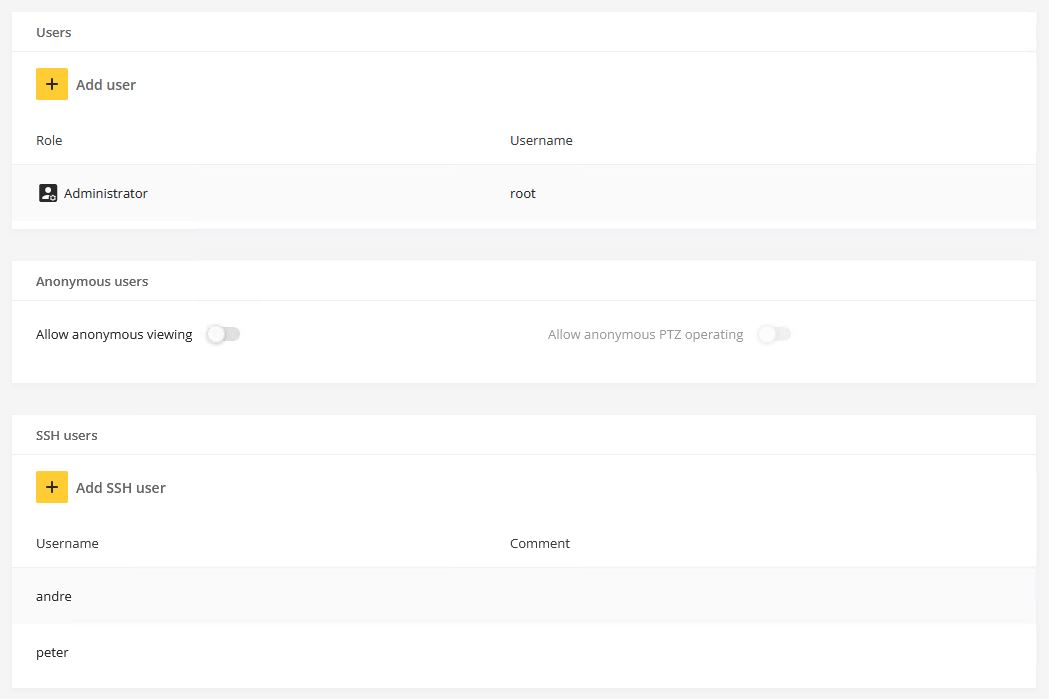
Command overview
The following main commands are available and supported when logged in via SSH to the Axis device. Make sure you are using the commands according to the instructions given by Axis Technical Services.
| Action / Purpose | Windows OS command line | Linux OS command line |
|---|---|---|
| Connect & login | ssh root@192.168.0.90 | ssh root@192.168.0.90 |
| Disconnect & logout | exit | exit |
| Restart | reboot | reboot |
| Download crash report | ssh root@192.168.0.90 /usr/sbin/dbox debugar.cgi -d > debug.tgz | ssh root@192.168.0.90 /usr/sbin/dbox debugar.cgi -d > debug.tgz |
| Upload AXIS OS* | scp C:\Users\psadmin\Downloads\P1375_9_80_2_4.bin root@172.25.201.191:/var/tmp | |
| Update AXIS OS | upgrade -f /var/tmp/P1375_9_80_2_4.bin | cat P1375_9_80_2_4.bin | ssh root@172.25.201.191 upgrade |
| Update AXIS OS & perform a factory default | upgrade -d -f /var/tmp/P1375_9_80_2_4.bin | cat P1375_9_80_2_4.bin | ssh root@172.25.201.191 upgrade -d |
| Perform a factory restore and keep IP settings | fwmgr factorydefault soft | fwmgr factorydefault soft |
| Perform a factory default | fwmgr factorydefault hard | fwmgr factorydefault hard |
*Uploading AXIS OS to the Axis device is only needed when the user is trying to update the device using the Windows OS command line. This step is not needed when using the Linux OS command line.
The commands below are illustrated using the Windows OS command lines from the table.
Connect & login
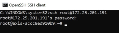
Disconnect & logout
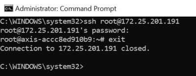
Download Crash Report
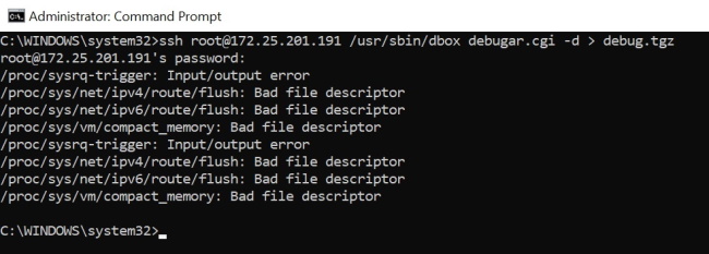
Restart
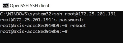
AXIS OS update
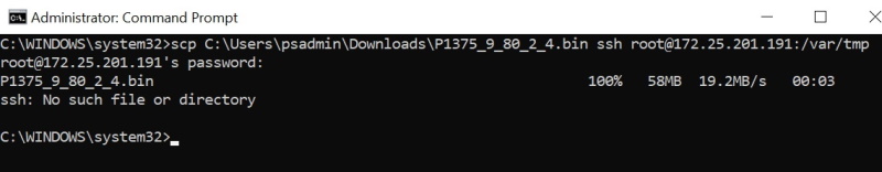
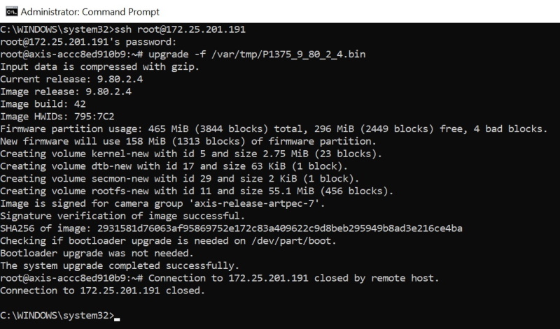
AXIS OS update & factory default

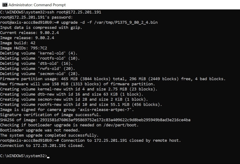
FTP access
- Only applicable for AXIS OS versions 11.0 and below. With AXIS OS 11.1 and later, the FTP options has been removed to increase overall minimum cybersecurity level. For more information, visit SSH access
- The below documentation should only be used according to the instructions given by Axis Technical Services in maintenance and troubleshooting situations.
Accessing the Axis device using FTP for maintenance purposes only is not recommended due to the connection being unencrypted and sensitive information being transferred in plain text readable. Therefore, SSH access is recommended. FTP access can be achieved using the plain Linux command console or Microsoft Windows power shell. Note that administrator privileges may be required for this and/or firewall and security settings of the computer need to be adjusted in order to allow FTP connections. FTP can be enabled in the Axis device via Plain config > Network > FTP. Alternatively FTP can be enabled/disabled using the direct VAPIX API calls:
https://ip-address/axis-cgi/param.cgi?action=update&Network.FTP.Enabled=Yes
https://ip-address/axis-cgi/param.cgi?action=update&Network.FTP.Enabled=No
Command overview
The following main commands are available and supported when logged in via FTP to the Axis device. Make sure you are using the commands according to the instructions given by Axis Technical Services.
| Action / Purpose | Windows OS command line |
| Connect & login | ftp 192.168.0.90 |
| Disconnect & logout | bye |
| Restart | quote site reboot |
| Download crash report* | get debug.tgz |
| Update AXIS OS* | put P1375_9_80_2_4.bin flash |
| Update AXIS OS & factory default* | put P1375_9_80_2_4.bin flash_all |
*The hash command followed by the bin command can be used to enable verbose logging prior to executing the selected commands.
Connect & login
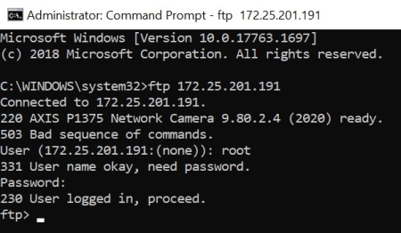
Disconnect & logout
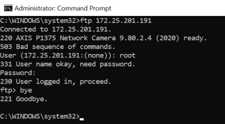
Download Crash Report
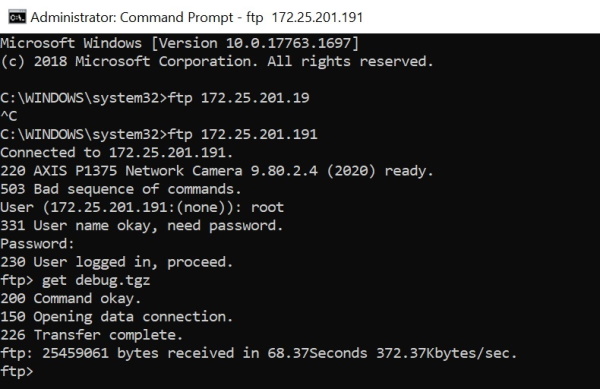
Restart
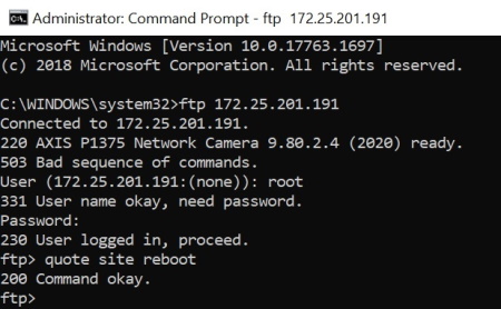
AXIS OS update
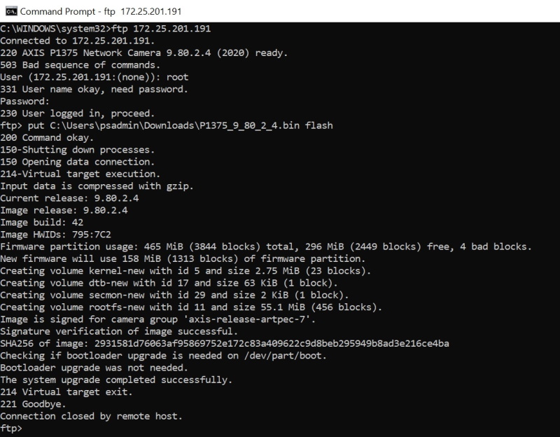
AXIS OS update & factory default

Network traffic shaping
Axis devices can transmit video using the Transmission Control Protocol (TCP) or the User Datagram Protocol (UDP). TCP has a control mechanism, so in the event a packet is being lost or corrupt, it will be resent. The UDP protocol doesn’t have a mechanism to ensure that all transmitted packets have been received. So, if a packet is discarded or corrupt, its retransmission is not requested. UDP is commonly used in multicast networks. The discarded packets associated with a video stream will result in unsatisfactory video performance as the associated pixels will not be displayed within the end users’ video. Packet drops are caused by different things, e.g. the incorrect specification of the network infrastructure, a network that had alterations over time (more traffic added), or a network that becomes congested at peak times. Network switches with insufficient processing power and memory capabilities will cause packet drops when faced with unexpected or inconsistent peaks of incoming data.
Axis devices will by default transmit their data as fast as possible and due to the nature of H.264 video, we encounter peaks or bursts of network traffic that is sent out by the Axis device into the network. The bursts or peaks of data are associated with the I-frames contained within the video stream, where the whole video frame is updated. In between the I-frames are the P-frames, which are much smaller in data size. This can cause issues when there is insufficient capacity on the network hardware and when using the UDP method of transmission.
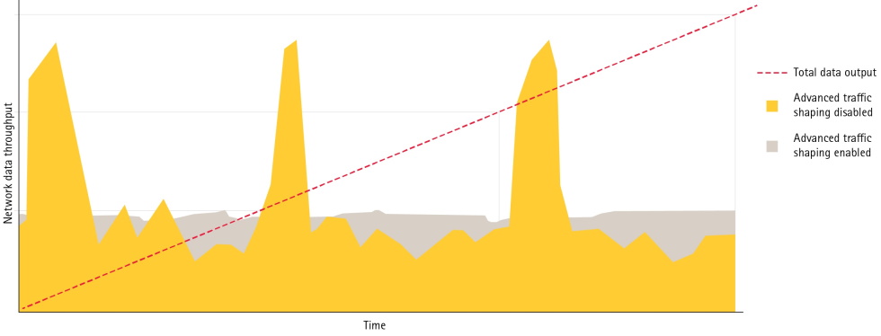
Network bottlenecks and throughput
Even though the network infrastructure through its switches and routers gets increased capabilities and become more powerful in dealing with network spikes and bursts, and even though it’s trying to overcome the temporal bottleneck by buffering the incoming data, this might eventually still fail depending on the setup.
Below are a couple of possible scenarios where traffic shaping is a recommended technique for avoiding network related issues. The use cases illustrate how to plan and manage network related traffic by understanding possible bottleneck positions within the network. This is done by simply computing the uplink speed of the network infrastructure and potential incoming data from e.g. Axis devices or other network equipment that coexists and contributes to data traffic in the network.
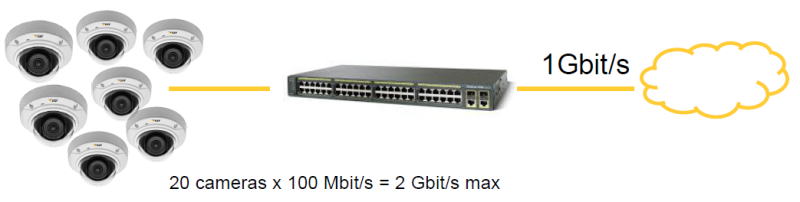
But it’s not only the uplink speed that is important. In some use cases the network equipment is simply not performant enough to cope with the amount of network traffic or spikes that might be generated. It’s also possible that the accumulative number of devices connected to the same network switch eventually will overwhelm it and cause it to drop network packets. Proactive planning of the expected network traffic and use case is key in avoiding potential issues.

Basic traffic shaping
There are several techniques for controlling the data output from an Axis device. The first step is to always use a suitable compression level to optimize the device’s output. H.264 compression is the industry standard method of compression due to its efficiency, but a suitable compression level must still be applied (this reduces the amount of data whilst maintaining picture quality). Axis Zipstream is an even more efficient compression algorithm, which increases the compression further whilst still maintaining picture quality when compared to H.264. H.264 and Zipstream algorithms are based on the movement or non-movement within a scene, and as such it’s quite difficult to predict the actual output of the camera. Maximum bitrate (MBR), variable bitrate (VBR) as well as average bitrate (ABR) are techniques to limit the output of a camera, and can be used to contain the transmitted data within a certain average perimeter. However this doesn’t restrict the actual peaks or bursts. Learn more about the different bit rate controls in the white paper Bitrate control for IP video.
A completely different example of applying basic traffic shaping is the simple decision between having two video streams per Axis device, one each for live view and recording versus using the same streaming and network parameters for reusing a single video stream for both live view and recording. Using only one video stream instead of two is reducing the amount of network throughput generated by the Axis device by 50%. This may even be enough to avoid network-related bottlenecks in an aggregated scenario of, let’s say, having many Axis devices being connected to a fully utilized 48-port network PoE switch.
Advanced traffic shaping
In case basic traffic shaping mechanics are not suitable, more advanced techniques can be applied on the network layer of the Axis device. To control peaks or bursts of data being transmitted from an Axis device, the bandwidth limit parameter in Plain Config > Bandwidth can be used. The bandwidth parameter was introduced in AXIS OS 6.20 and makes use of the hierarchical token bucket (HTB) and token bucket filter (TBF). TBF controls the transmitted output by controlling the data by the use of a token. When a token is available – data can be sent. The bandwidth limit is not the capped data rate but what HTB/TBF uses to organize the data output in a controlled manner.
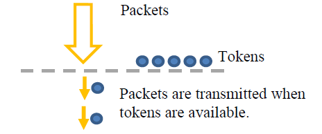
TBF is a queuing method that acts as a timing mechanism which effectively spreads peaks of data over a longer period. More information about HTB and TBF can be found via the following links:
Configuration in AXIS OS
The bandwidth parameter can be found in Plain Config > Bandwidth. When limiting the traffic you need to set a bandwidth limit value that matches your total bandwidth needs from your Axis device. It’s recommended to gather statistics from the network switch that the Axis device is connected to in order to learn the usual bandwidth usage. As an example, an Axis device under operation is a multisensor device with four image sensors and a combined quad view that sends out two streams each per channel for recording and live view. These 10 parallel video streams generate an average network bandwidth consumption of 70-80 Mbit/s. To include some margin, the bandwidth parameter should be configured to 100mbit or 125mbit.
The Axis device will drop packets if the bandwidth parameter is configured unreasonably, i.e. lower or very close to the actual network bandwidth consumption. Applying good margin above the actual network bandwidth consumption is always recommended. The bandwidth limit is not the capped data rate but what HTB/TBF uses to organize the data output in a controlled manner.
Example 1: Default configuration, 0 means no traffic shaping is applied.
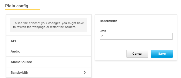
Example 2: Traffic shaping is enabled, and the maximum output is capped at 100 mbit/s.
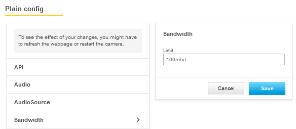
Example 3: Traffic shaping is enabled, and the maximum output is capped at 10000 kbit/s (=10 mbit/s).
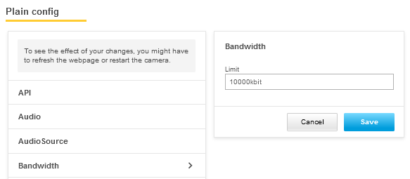
Wireshark network analysis
Filters and macros
This is a list of common basic operators as well as network and video streaming related filters that are useful when troubleshooting network traffic between an Axis device, the network infrastructure and third party video management systems and other applications.
| Basic operators | Description |
| == | Equal |
| != | Not equal |
| > | Greater than |
| < | Less than |
| ≥ | Greater than or equal to |
| ≤ | Less than or equal to |
| && | And |
| ! | Not |
| || | Or |
| Network display filter | Description |
| ip.addr ≥ 224.0.0.0 | Filter for network traffic with IP-Multicast addresses |
| ip.addr == 172.25.201.0/24 | Filter for network traffic with IP-address sub net |
| ip.addr == 10.0.0.1 | Filter for network traffic with IP-address 10.0.0.1 |
| ip.addr ==10.0.0.1 && ip.addr ==10.0.0.2 | Filter for network traffic with IP-address 10.0.0.1 and 10.0.0.2 |
| ipv6.addr == 2019:db8:abcd:a:3cf5:6c7e:f780:1085 | Filter for network traffic with IPv6 address 2019:db8:abcd:a:3cf5:6c7e:f780:1085 |
| ! (ip.addr == 172.25.154.7) | Filter for network traffic excluding this specific IP-address |
| ip.dst == 10.0.0.1 | Filter for network traffic with a specific IP-address 10.0.0.1 as destination |
| ip.src == 10.0.0.1 | Filter for network traffic with a specific IP-address as source |
| eth.dst == 00:00:cd:37:00:c0 | Filter for network traffic with a specific destination MAC address |
| eth.src == ac:cc:8e:c2:22:7b | Filter for network traffic with a specific source MAC address |
| icmp | Filter for ICMP traffic (ping) |
| ! icmp.resp_in and icmp.type==8 | Filter for ICMP traffic (ping) that did not respond/failed |
| dns | Filter for DNS traffic |
| ntp | Filter for NTP traffic |
| igmp | Filter for IGMP traffic |
| eap || eapol | Filter for 802.1x traffic |
| snmp | Filter for SNMP traffic |
| http | Filter for HTTP traffic |
| http.request | Filter for HTTP GET requests |
| http.request.full_uri contains "onvif" | Filter for HTTP Get Requests containing ONVIF related information |
| http.request.full_uri contains "action=update" | Filter for HTTP Get Requests where a VAPIX param.cgi parameter is changed |
| http.time > 2 | Filter for HTTP responses that were sent longer than 2 seconds after the request. |
| !(arp or icmp or dns) | Exclude network traffic related to ARP, ICMP and DNS protocol |
| udp contains 33:27:58 | Sets a filter for the HEX values of 0x33 0x27 0x58 at any offset |
| tcp contains traffic | Filter for TCP packets that contain the word ‘traffic’ in their payload |
| tcp.flags.reset == 1 | Filter for TCP resets |
| tcp.analysis.retransmission | Filter for TCP retransmissions |
| tcp.analysis.out_of_order | Filter for multiple paths between source and destination |
| tcp.analysis.window_full | Filter for TCP Window Buffer Full Condition |
| tcp.analysis.zero_window | Filter for TCP Window Buffer Full Condition |
| frame.time_delta > 0.04 | Filter for network traffic that are send with 40ms or more latency compared to the previous packet |
| tcp.port == 80 | Filter for network traffic with TCP port 80 |
| udp.port == 64000 | Filter for network traffic with UDP port 64000 |
| udp.srcport==50000 | Filter for network traffic with UDP source port 50000 |
| udp.dstport==50001 | Filter for network traffic with UDP destination port 50001 |
| smb2 || smb | Filter for SMB network protocol traffic |
| p.dsfield.dscp == 0x0b | Filter for Quality of Service DSCP values, a Hex converter is needed to convert the 0x00 values |
| macc.opcode == pause | Filter for Ethernet Pause-Frames |
| Video streaming display filter | Description |
| rtsp.request | Filter for RTSP requests such as Options, Get Parameter, Play, Setup etc.. |
| rtsp contains "backchannel" | Filter for RTSP streams using ONVIF backchannel |
| rtsp contains "onvif" | Filter for RTSP streams using the onvif protocol |
| rtsp || h264 | Filter for RTSP and H.264 decoded RTP streams |
| rtp.ssrc == 0x76747D52 | Filter for RTP streams with specific source ID |
| rtp contains "VirtualInput" | Filter for RTP streams containing specific keywords to identify metadata such as the Virtual Input |
| (ip.src==10.25.195.92 && udp.srcport==50000 && ip.dst==10.25.185.75 && udp.dstport==31018 && rtp.ssrc==0x9c37fd6) | Filter for RTP stream with a number of specific details |
| h264.nal_unit_type == 1 | Filter for P-Frames only |
| h264.nal_unit_type == 5 | Filter for I-Frames only |
| h264.start.bit == 1 && h264.slice_type == 2 | Filter for I-Frame start packages only |
| h264.start.bit == 1 && h264.slice_type == 0 | Filter for P-Frame start packages only |
| h264.nal_unit_hdr == 6 | Filter for SEI Frames (UserData needs to be enabled in the Axis device) |
| h264.nal_unit_hdr == 7 | Filter for SPS Frames |
| h264.nal_unit_hdr == 8 | Filter for PPS Frames |
| rtp.ext eq 1 | Filter for SRTP (RTSPS) streams |
| rtp.ext.rfc5285.id eq 14 | Filter for SRTP (RTSPS) streams |
Coloring and column preferences
In Wireshark, you can set coloring rules and select and organize columns to get a better overview of the network traffic. In the following screenshots you will see how this can be configured.
With coloring rules it's possible to highlight certain types of network traffic - e.g. RTSP/RTP - in a certain color, which makes it easier to identify for the user. Configuring coloring rules works in the same way as setting display filters in Wireshark, and you can actually use the same filters.
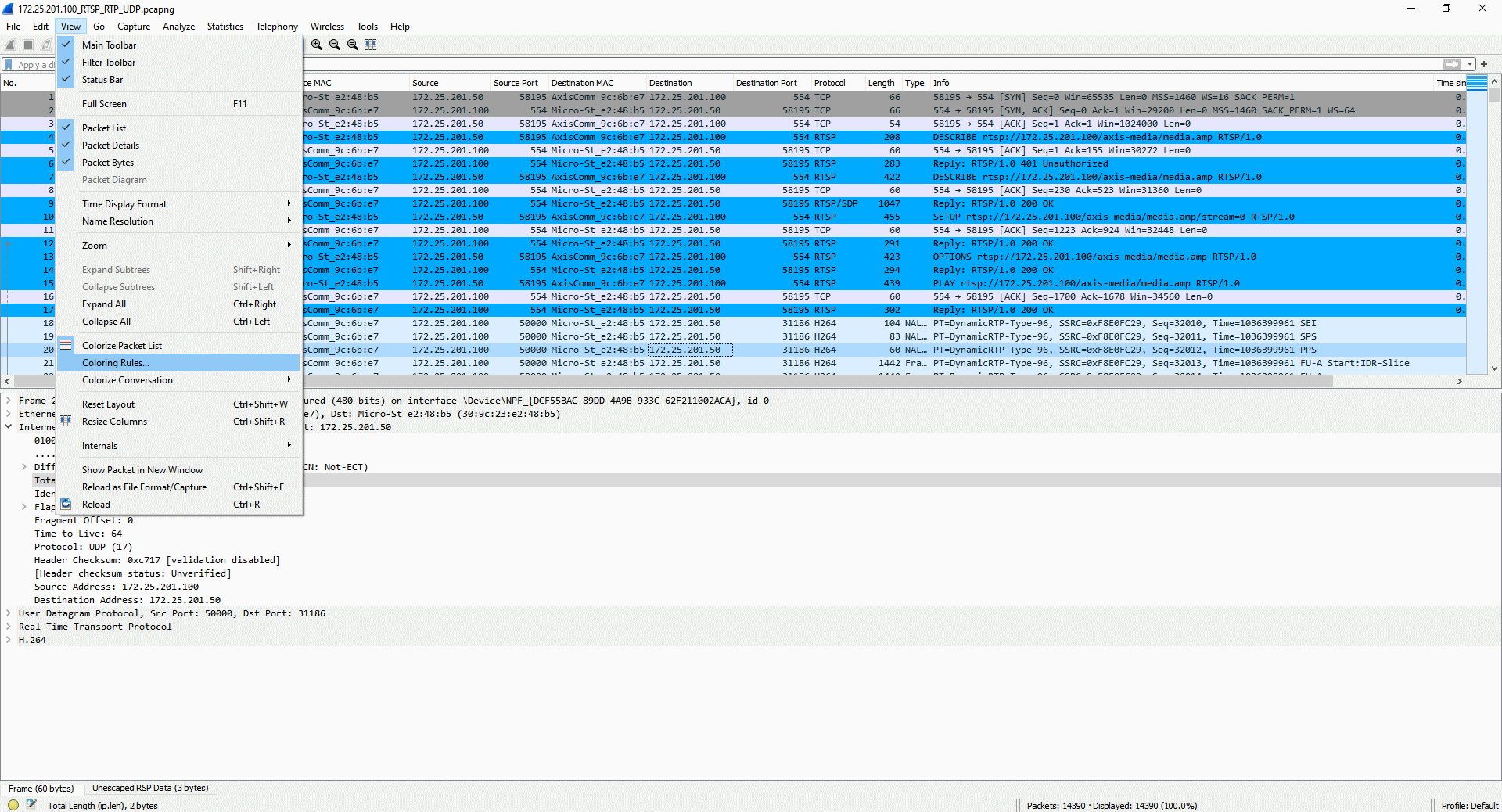
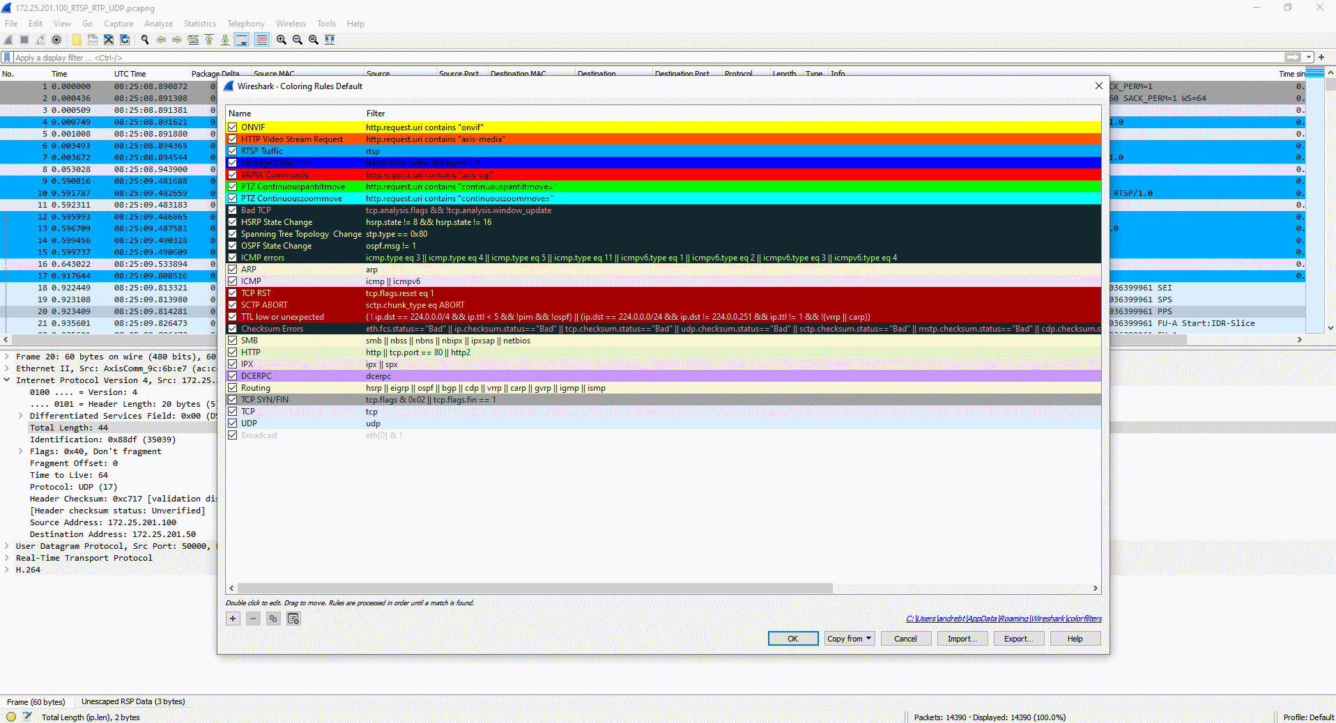

Columns can be selected and organized to make the network traffic analysis more logical and the information more easily accessible, e.g. when following traffic from two network devices in the network.
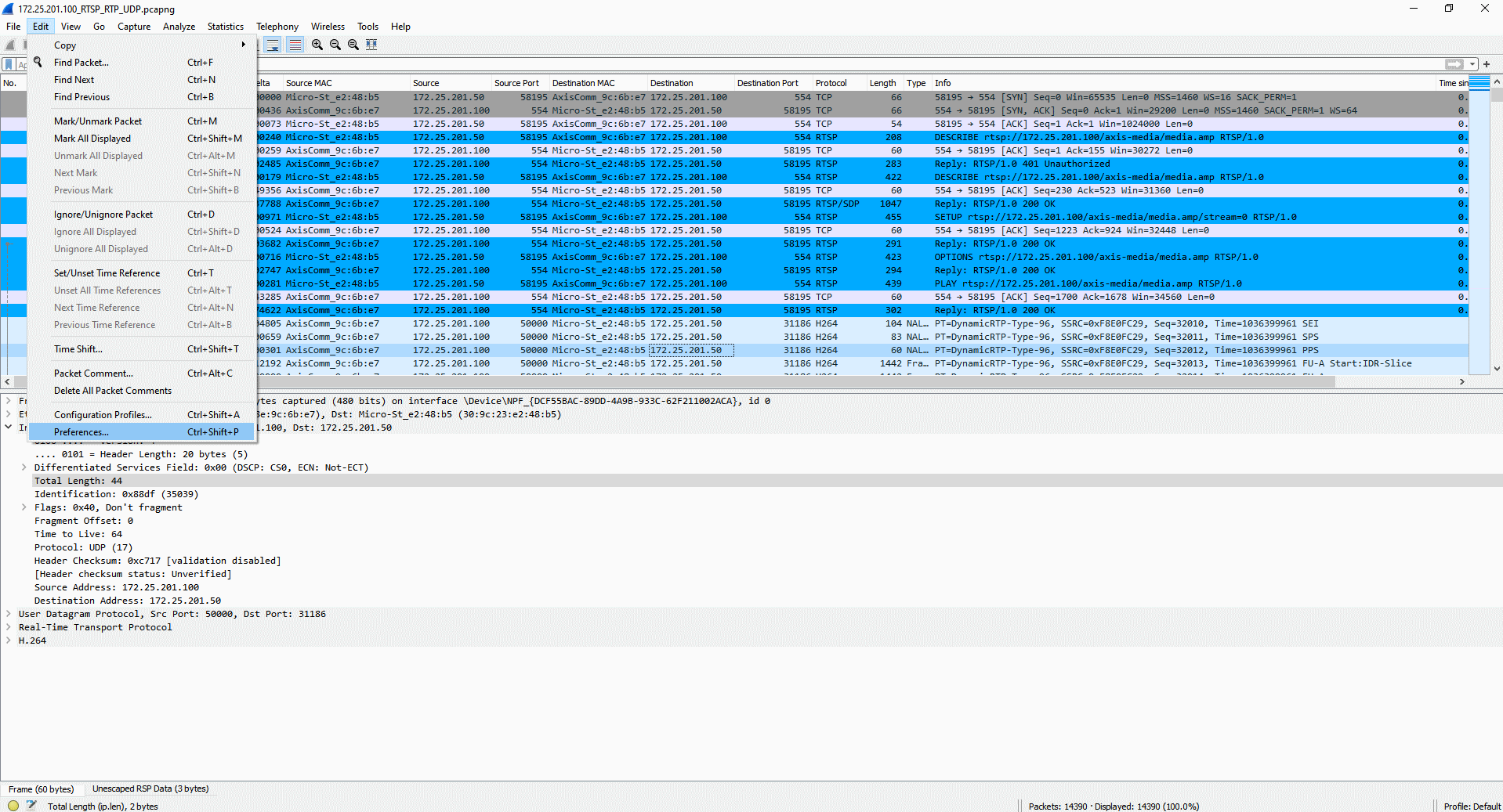
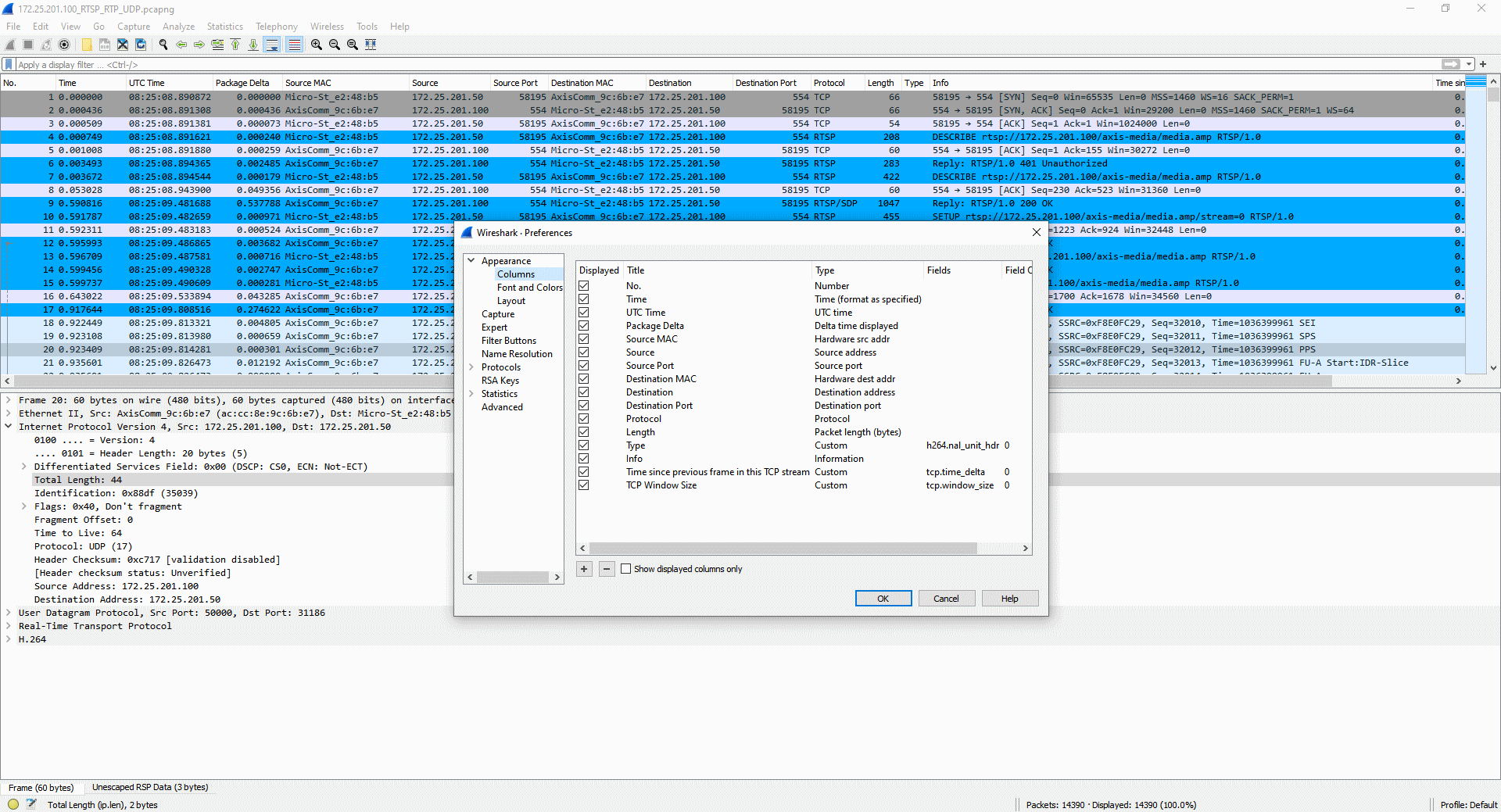
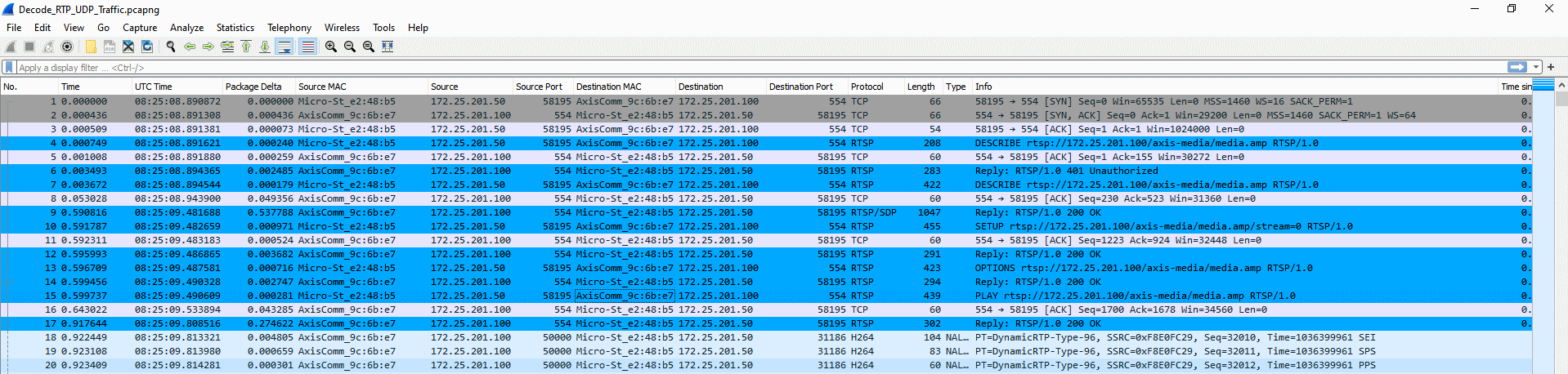
Decode RTP/UDP traffic
In order to analyze H.264 network related traffic successfully, it's essential that you configure Wireshark to decocde video streaming related traffic. With this in place, more useful display filters can be used too. The following screenshots illustrate the correct configuration (i.e. H.264 dynamic payload types set to "96") to decode RTP network traffic transported via UDP since H.264 needs to be in place for that.
This network trace can be used for testing the steps below.

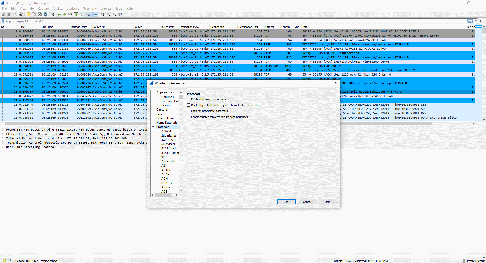
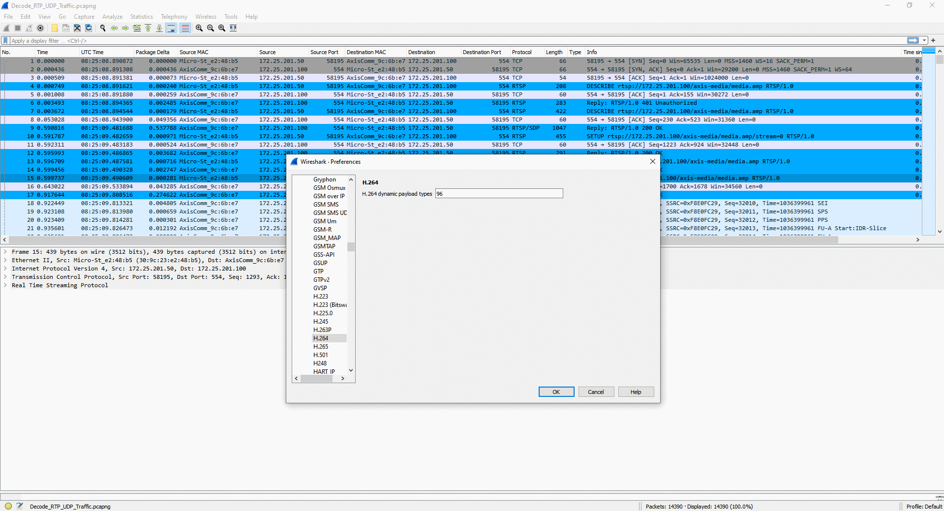
Decode RTP/TCP traffic
In order to analyze H.264 network related traffic successfully, it's essential that you configure Wireshark to decocde video streaming related traffic. With this in place, more useful display filters can be used too. The following screenshots illustrate the correct configuration (RTP over RTSP encapsulated) to decode RT(S)P network traffic transported via TCP since H.264 needs to be in place for that.
This network trace can be used for testing the steps below.
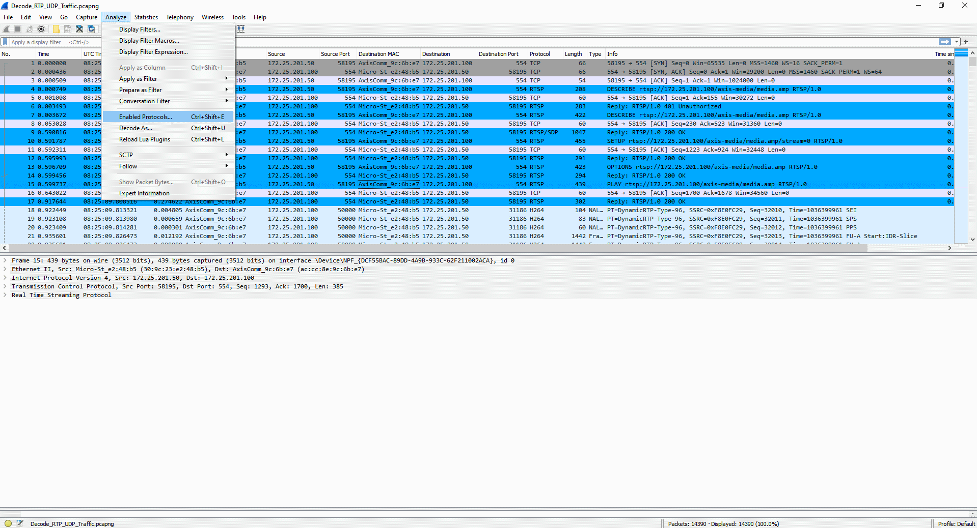
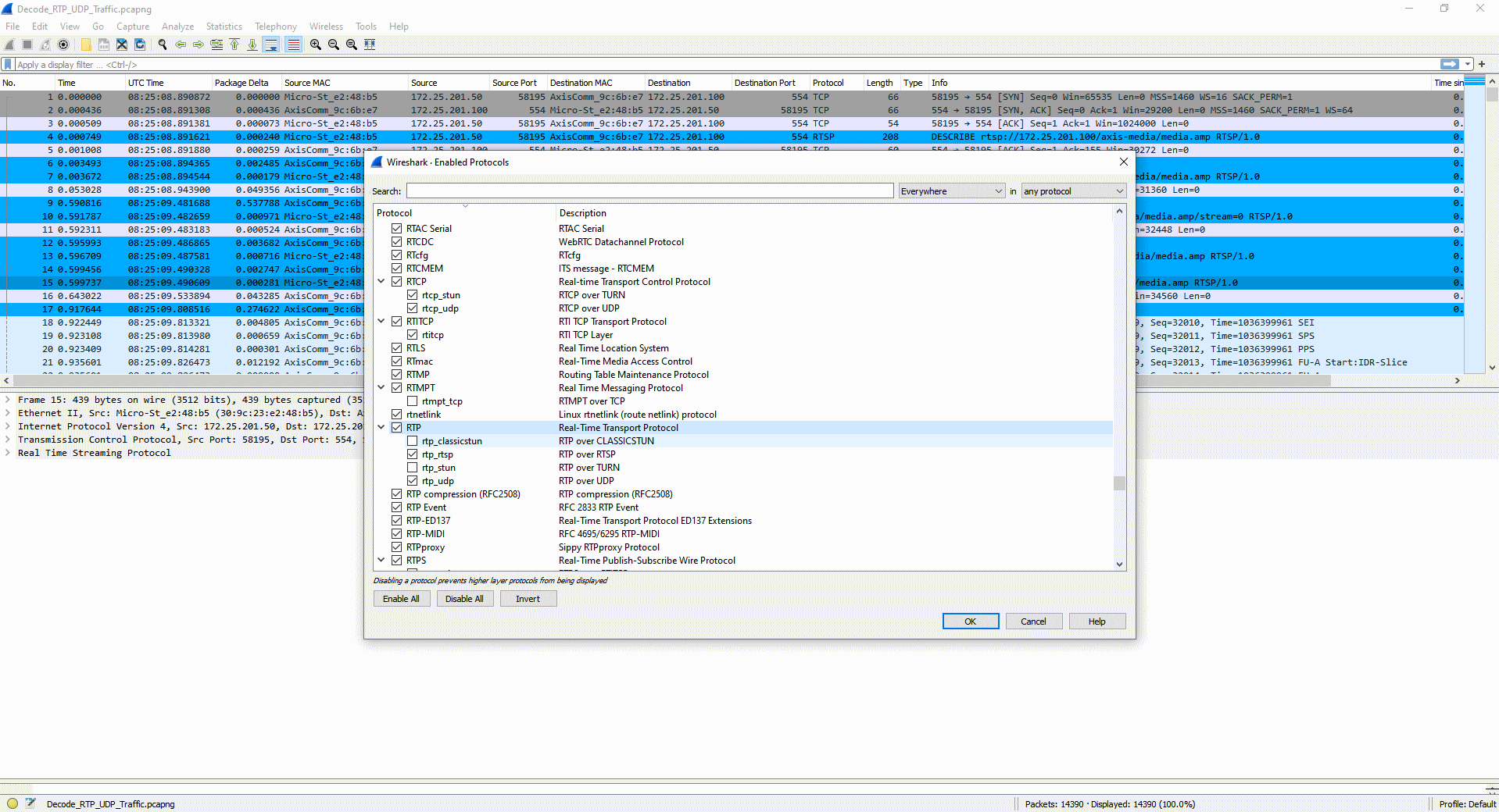
Network bandwidth analysis
Analyzing the amount of network bandwidth between network devices can be used to identify network bottlenecks and overuse of the existing network infrastructure. Another aspect of this analysis is to identify network peaks (i.e. moments where exceptionally large amounts of network traffic is sent), which is a common behavior due to the low-size P-Frames and larger I-Frames in H.264 video streaming.
The following screenshots illustrate how to identify the amount of network traffic sent from one network device to another. This information can then be cross-referenced against other measuring tools, such as Windows Task Manager.
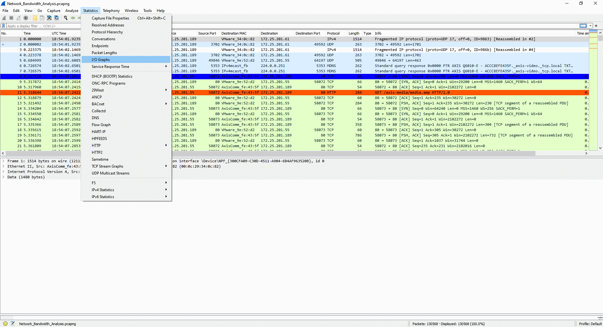
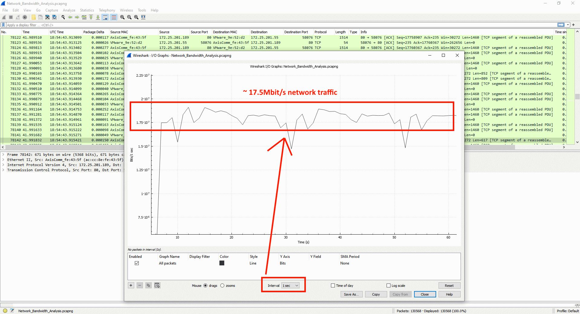
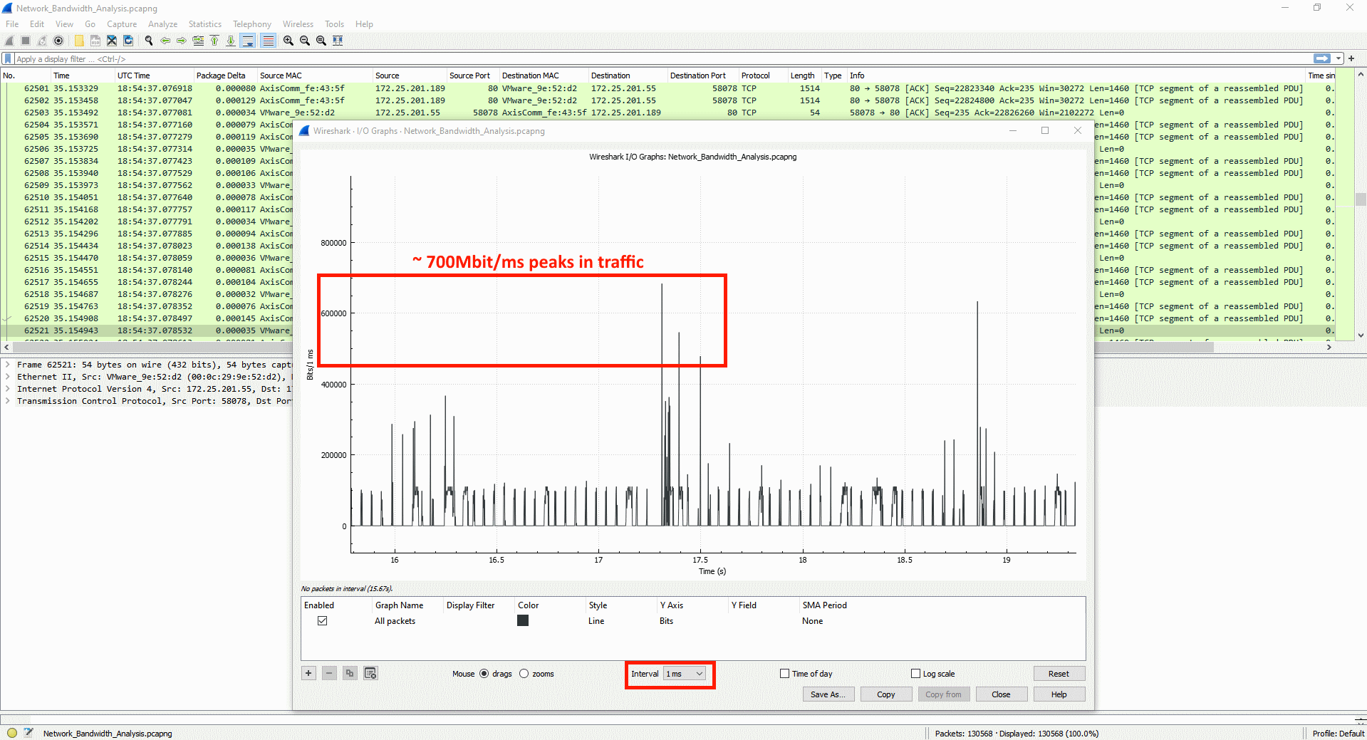
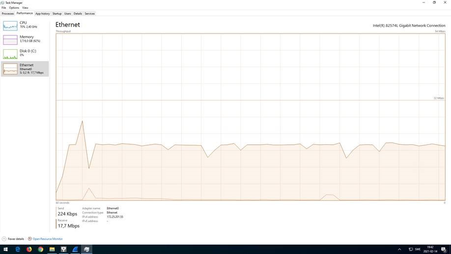
Useful information can also be found in the capture statistics of the network trace file.
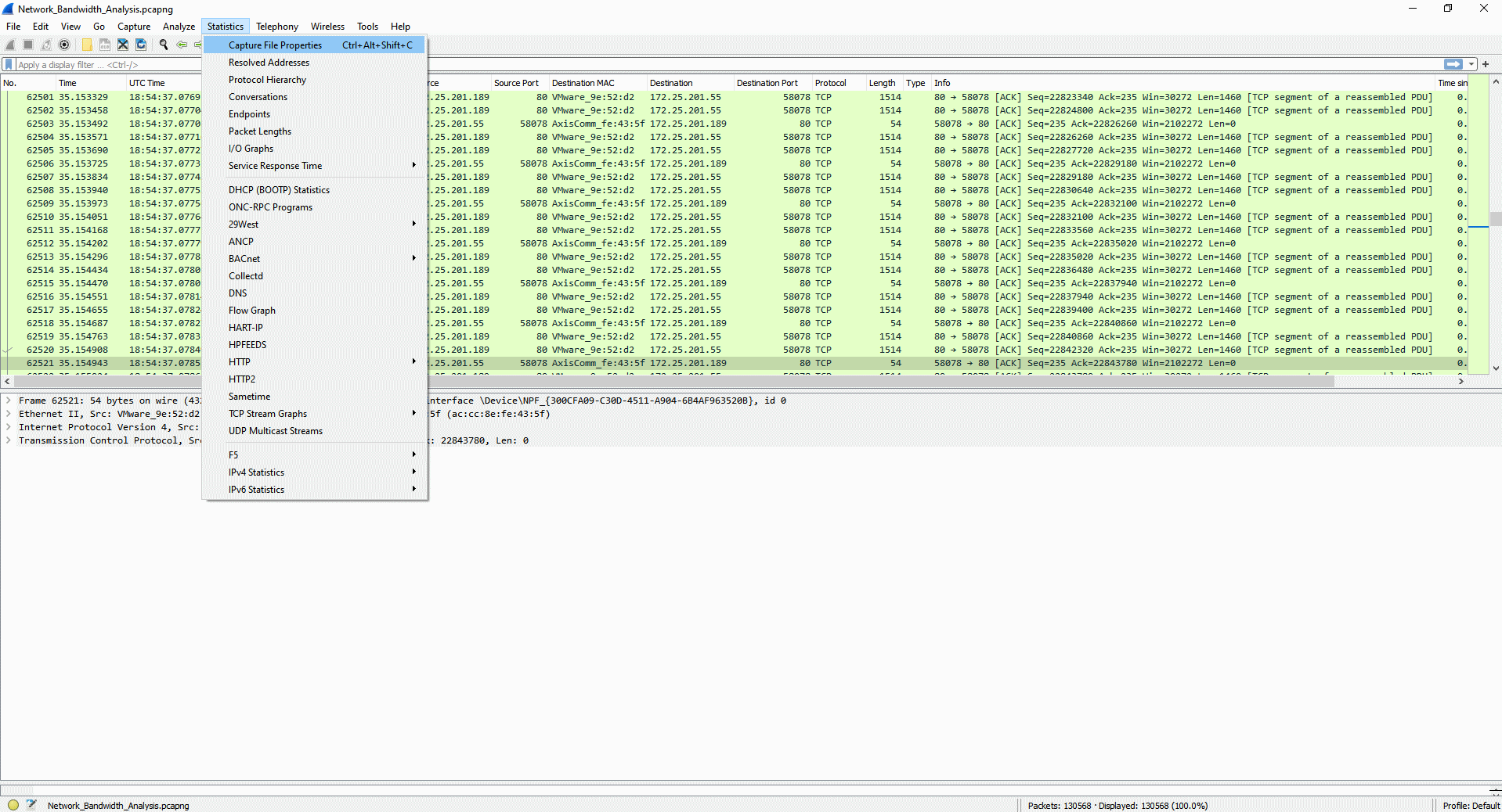
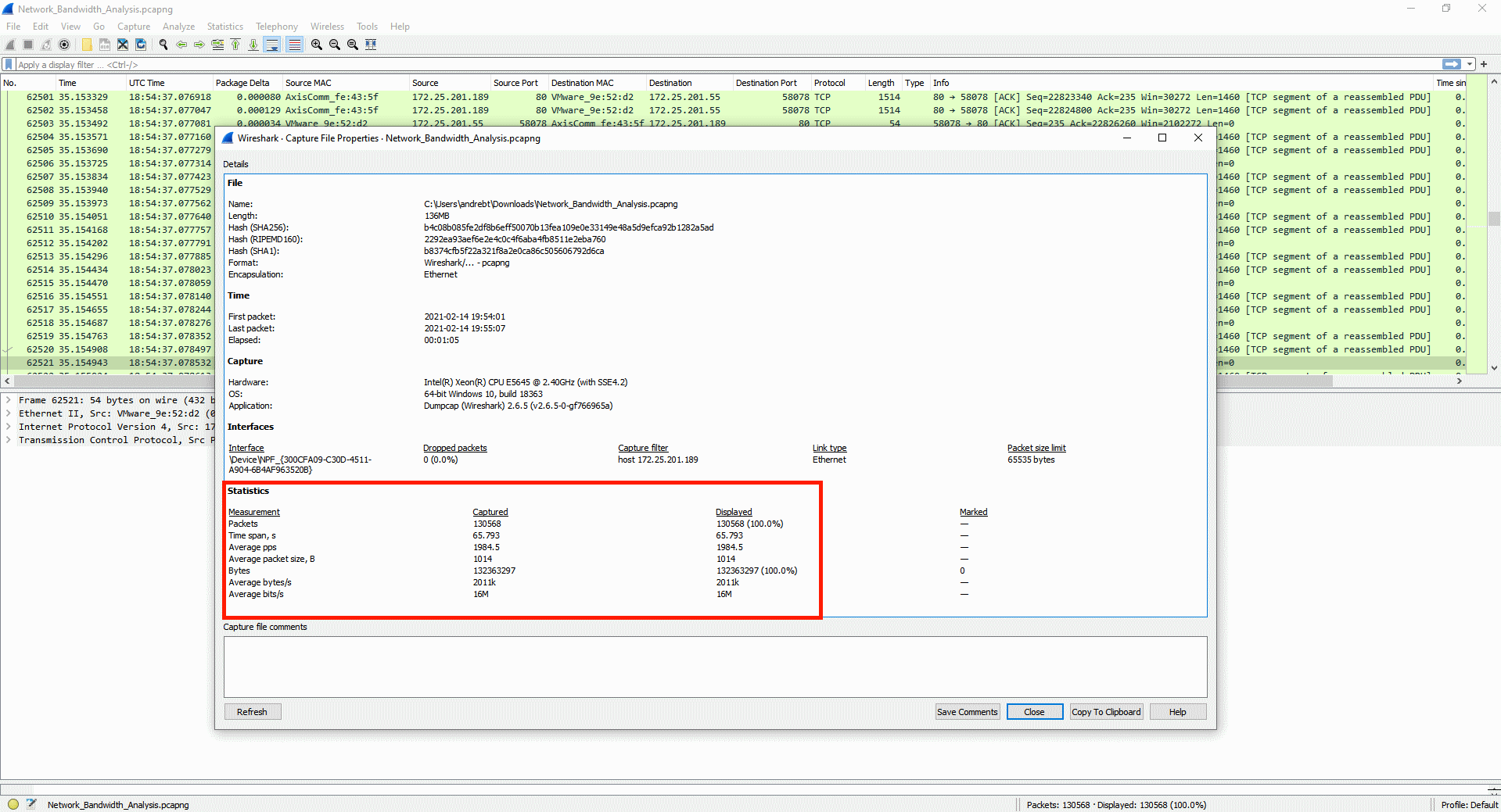
Limit network captures
During troubleshooting it’s sometimes required to take Wireshark captures over a longer period of time since it’s uncertain when a problem appears. As this typically requires a lot of disk space, it’s recommended to limit the Wireshark capture. This can be done by using the options below and dumpcap, which is part of Wireshark. The default installation path for dumpcap is: C:\Program Files\Wireshark\
| Command line option | Description |
|---|---|
| -D | Find interface number. |
| -i | The interface number the capture should be done on. |
| -q | Quiet mode, eliminates displaying packet count. |
| -b filesize:n | The file size to create in KB per capture file. |
| -b duration:n | The amount of time in seconds to run per capture file. |
| -b files:n | The maximum number of files to create. Once the maximum number of files have been saved, the oldest file is deleted and a new empty file is created in its place. |
| -f | The capture filter. For more information, see this page. |
| -w <path>.pcap | The location to write the output files. The path specified must exist. |
When using the "-b files:n" option the contents of the specified traces folder would contain files with a sequence number and timestamp as follows: mytrace_00001_20220626164602.pcap . . . mytrace_00024_20220627154602.pcap.
| Variable | Description |
|---|---|
| mytrace | Name of the trace. |
| 00001 | File sequence number. |
| 2022 | Year. |
| 0626 | Month/day. |
| 164202 | Hour/min/sec in 24 h format. The time indicates when the file capture was "started". |
Example use cases:
| Example | Output |
|---|---|
| dumpcap -i 3 -q -b duration:3600 -b files:10 -w c:\traces\mytrace.pcap | 10 capture files x 1 hour long. |
| dumpcap -i 3 -q -b duration:3600 -b files:10 -f "host 192.168.0.90" -w c:\traces\mytrace.pcap | 10 capture files x 1 hour long + a capture filter to only capture traffic for the IP "192.168.0.90". |
| dumpcap -i 3 -q -b filesize:200000 -b files:10 -w c:\traces\mytrace.pcap | 10 capture files x 200 MB. |
Server report
The server report includes actual, and to some extent historical, information about health-monitoring, general system and configuration information, as well as valuable log files. Information that will help Axis Technical Support to analyze your device. Always include a server report when contacting AXIS Support.
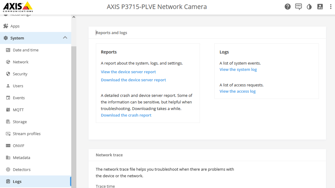
The server report can be downloaded as a .zip file.
| AXIS OS version | Web interface download instructions |
|---|---|
| < 7.10 | Setup > System Options > Support > Logs & Reports > Download Server Report |
| ≥ 7.10 | Settings > System > Maintenance > Download Server Report |
| ≥ 10.9 | System > Logs > Download the device server report |
AXIS Server Report Viewer
AXIS Server Report Viewer is a web based, graphical user interface that makes it possible to upload and visualize the data of the server report. The tool is developed by Axis and greatly enhances the speed and efficiency of analyzing the data in the server report.
You can access AXIS Server Report Viewer after logging in to www.axis.com with your MyAxis account.
Watch the introduction video to learn more about AXIS Server Report Viewer.
AXIS VAPIX® Test Tool
The purpose of this tool is to aid in the troubleshooting of the Axis VAPIX® library requests when used in conjunction with the device event system as described in the Get started with rules for events section of the Axis documentation.
You can download the tool here: AXIS VAPIX® Test Tool.
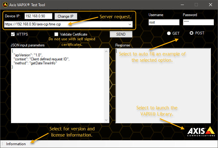
Product specific information
Hardware changes
When Axis makes hardware changes to an existing model that are not backwards-compatible, the device is assigned a new hardware ID. This is because updated components may require adjustments in how AXIS OS interacts with the hardware.
All Axis models have a hardware ID that is used to identify their specific hardware configuration, which may lead to older units of a model may having one hardware ID, while newer units of the same model may have a different one.
Axis aims to minimize changes to hardware IDs for existing models whenever possible. Historically, such changes have been rare, but in recent years, global component shortages have led to updates in some products already on the market, resulting in new hardware IDs.
All AXIS OS versions have a reference to the hardware ID that it supports. When a device gets a new hardware ID, it is released on the latest available versions of the Active and LTS tracks for that model. This means that if you already have a particular device and you buy a new one of the same model that has had a hardware ID change, it won’t be possible to downgrade the new model to an older AXIS OS version that doesn’t support the new hardware ID. The same device with the previous hardware ID supports all AXIS OS versions released since that hardware ID was introduced.
To be transparent about the changes made, we have listed all the products affected by hardware ID changes. See the table below to find the minimum OS version you need to use to avoid issues when downgrading.
As always, we recommend using the latest supported OS version on the track you are using, to be sure of having the latest patches and security updates. Read more about the AXIS OS tracks in the AXIS OS Lifecycle guide and follow the updates in each track in the AXIS OS Release notes.
The minimum active is not recommended if there is a later version LTS available, since they no longer are supported and are replaced by the newer LTS.
The minimum LTS 6.50 or 8.40 is not recommended if there is a higher version of LTS available as this is no longer maintained.
| Product | Track | Version | Release date |
| AXIS A8105-E | LTS 2016 | 1.58.2.2 | 2017-04-21 |
| AXIS A8207-VE Mk II | Active (legacy) | 11.0.89 | 2022-09-21 |
| Product | Track | Version | Release date |
| AXIS C1310-E | Active (legacy) | 10.12.66.1 | 2022-07-08 |
| Active (legacy) | 10.10.73.3 | 2022-05-25 |
| Product | Track | Version | Release date |
| AXIS Companion 360 | Active (legacy) | 8.40.1 | 2018-09-19 |
| Active (legacy) | 7.15.2.2 | 2017-10-30 | |
| AXIS Companion Cube L/LW | LTS 2020 | 9.80.1.2 | 2020-05-20 |
| LTS 2018 | 8.40.1 | 2018-09-19 | |
| Active (legacy) | 7.40.1 | 2017-11-30 | |
| AXIS Companion Dome V/WV | LTS 2020 | 9.80.1 | 2020-05-04 |
| LTS 2018 | 8.40.1 | 2018-09-19 | |
| Active (legacy) | 7.40.1 | 2017-11-30 | |
| AXIS Companion Recorder 8CH/4CH | LTS 2020 | 9.80.1 | 2020-05-04 |
| Active (legacy) | 1.11.1.3 | 2017-11-10 |
| Product | Track | Version | Release date |
| AXIS M1045-LW | LTS 2020 | 9.80.1 | 2020-05-04 |
| LTS 2018 | 8.40.1 | 2018-09-19 | |
| Active (legacy) | 7.40.1 | 2017-11-30 | |
| AXIS M1065-L/-LW | LTS 2020 | 9.80.1.2 | 2020-05-20 |
| LTS 2018 | 8.40.1 | 2018-09-19 | |
| Active (legacy) | 7.40.1 | 2017-11-30 | |
| AXIS M1124/-E AXIS M1125/-E | LTS 2020 | 9.80.1 | 2020-05-04 |
| LTS 2018 | 8.40.1 | 2018-09-19 | |
| Active (legacy) | 8.15.1 | 2018-03-18 | |
| LTS 2016 | 6.50.1.2 | 2017-06-14 | |
| AXIS M1134 AXIS M1135/-E AXIS M1137/-E | LTS 2022 | 10.12.104 | 2022-09-05 |
| Active (legacy) | 10.3.0.1 | 2021-01-11 | |
| LTS 2020 | 9.80.3.1 | 2021-03-03 | |
| AXIS M2026-LE Mk II | LTS 2020 | 9.80.1 | 2020-05-04 |
| LTS 2018 | 8.40.1 | 2018-09-19 | |
| Active (legacy) | 7.30.1.1 | 2017-10-16 | |
| AXIS M3044-V/-WV AXIS M3045-V/-WV | LTS 2020 | 9.80.1 | 2020-05-04 |
| LTS 2018 | 8.40.1 | 2018-09-19 | |
| Active (legacy) | 7.40.1 | 2017-11-30 | |
| AXIS M3046-V | LTS 2020 | 9.80.1 | 2020-05-04 |
| LTS 2018 | 8.40.1 | 2018-09-19 | |
| Active (legacy) | 6.15.7.2 | 2017-10-18 | |
| AXIS M3047-P AXIS M3048-P | LTS 2018 | 8.40.1 | 2018-09-19 |
| Active (legacy) | 7.15.2.2 | 2017-10-30 | |
| AXIS M3067-P AXIS M3068-P | LTS 2022 | 10.12.104 | 2022-09-05 |
| Active (legacy) | 10.11.87 | 2022-06-16 | |
| LTS 2020 | 9.80.3.13 | 2022-07-22 | |
| AXIS M3088-V | Active | 12.1.60 | 2024-11-13 |
| LTS 2024 | 11.11.127 | 2024-12-06 | |
| AXIS M3106-L/-LVE Mk II | LTS 2020 | 9.80.1 | 2020-05-04 |
| LTS 2018 | 8.40.1 | 2018-09-19 | |
| Active (legacy) | 7.30.1.1 | 2017-10-20 | |
| AXIS M3115-LVE AXIS M3116-LVE | LTS 2022 | 10.12.104 | 2022-09-05 |
| Active (legacy) | 10.11.85 | 2022-06-14 | |
| LTS 2020 | 9.80.3.13 | 2022-07-22 | |
| AXIS M3128-LVE | Active | 12.1.60 | 2024-11-13 |
| LTS 2024 | 11.11.128 | 2024-12-18 | |
| AXIS M4216-V/-LV | Active (legacy) | 11.0.89 | 2022-09-21 |
| Active (legacy) | 10.12.73 | 2022-07-13 | |
| AXIS M4218-V AXIS M4218-LV | Active | 12.1.60 | 2024-11-13 |
| LTS 2024 | 11.11.127 | 2024-12-06 | |
| AXIS M5074 AXIS M5075 | Active | 12.3.56 | 2025-02-24 |
| LTS 2024 | 11.11.135 | 2025-02-10 | |
| AXIS M5075-G | Active | 12.3.64 | 2025-03-05 |
| LTS 2024 | 11.11.135 | 2025-02-10 |
| Product | Track | Version | Release date |
| AXIS P1375 | Active (legacy) | 11.0.89 | 2022-09-21 |
| Active (legacy) | 10.12.65 | 2022-07-01 | |
| LTS 2020 | 9.80.28 | 2023-04-21 | |
| AXIS P1375-E | Active (legacy) | 11.2.53 | 2022-12-22 |
| LTS 2022 | 10.12.135 | 2022-12-09 | |
| AXIS P1377 ExCam XF P1377 F101-A XF P1377 AXIS P1378 | Active (legacy) | 11.0.89 | 2022-09-21 |
| Active (legacy) | 10.12.65 | 2022-07-01 | |
| LTS 2020 | 9.80.3.13 | 2022-07-22 | |
| AXIS P1377-LE AXIS P1378-LE | Active (legacy) | 11.2.53 | 2022-12-22 |
| LTS 2022 | 10.12.135 | 2022-12-09 | |
| LTS 2020 | 9.80.28 | 2023-04-21 | |
| AXIS P1385 AXIS P1385-B AXIS P1385-BE AXIS P1385-E | Active | 12.0.91 | 2024-09-30 |
| LTS 2024 | 11.11.124 | 2024-11-25 | |
| AXIS P1387 AXIS P1387-B AXIS P1387-BE AXIS P1387-LE | Active | 12.2.61 | 2025-01-22 |
| LTS 2024 | 11.11.124 | 2024-11-25 | |
| AXIS P1388 AXIS P1388-B AXIS P1388-BE AXIS P1388-LE | Active | 12.2.61 | 2025-01-22 |
| LTS 2024 | 11.11.124 | 2024-11-25 | |
| AXIS P1447-LE AXIS P1448-LE | LTS 2022 | 10.12.104 | 2022-09-05 |
| Active (legacy) | 10.3.0.1 | 2021-01-11 | |
| LTS 2020 | 9.80.3.1 | 2021-03-03 | |
| AXIS P1455-LE | LTS 2022 | 10.12.104 | 2022-09-05 |
| Active (legacy) | 10.8.3 | 2021-11-30 | |
| AXIS P1465-LE AXIS P1465-LE-3 | Active | 12.1.60 | 2024-11-13 |
| LTS 2024 | 11.11.124 | 2024-11-25 | |
| AXIS P3224-LV/-V Mk II AXIS P3225-LV/-LVE/-V/-VE Mk II | LTS 2020 | 9.80.1 | 2020-05-04 |
| LTS 2018 | 8.40.1 | 2018-09-19 | |
| Active (legacy) | 7.40.1.1 | 2018-01-31 | |
| AXIS P3245/-LV/-LVE/-V/-VE | LTS 2022 | 10.12.104 | 2022-09-05 |
| Active (legacy) | 10.11.85 | 2022-06-14 | |
| LTS 2020 | 9.80.3.13 | 2022-07-22 | |
| AXIS P3245-LVE 22mm | LTS 2022 | 10.12.104 | 2022-09-05 |
| Active (legacy) | 10.4.3 | 2021-03-10 | |
| AXIS P3247-LV/-LVE | LTS 2022 | 10.12.104 | 2022-09-06 |
| Active (legacy) | 10.11.89 | 2022-06-20 | |
| LTS 2020 | 9.80.3.13 | 2022-07-22 | |
| AXIS P3248-LV/-LVE | LTS 2022 | 10.12.104 | 2022-09-06 |
| Active (legacy) | 10.11.89 | 2022-06-2 | |
| LTS 2020 | 9.80.3.13 | 2022-07-22 | |
| AXIS P3267-LV/-LVE AXIS P3268-LV/-LVE | Active (legacy) | 11.0.89 | 2022-09-21 |
| Active (legacy) | 10.12.55 | 2022-06-16 | |
| AXIS P3727-PLE | LTS 2022 | 10.12.104 | 2022-09-05 |
| Active (legacy) | 10.7.8 | 2021-10-29 | |
| AXIS P3738-PLE | Active | 12.1.60 | 2024-11-13 |
| AXIS P3925-LRE | Active (legacy) | 11.0.89 | 2022-09-21 |
| LTS 2022 | 10.12.104 | 2022-09-05 | |
| LTS 2020 | 9.80.3.14 | 2022-09-07 | |
| AXIS P3925-R | Active (legacy) | 11.0.93 | 2022-09-30 |
| LTS 2022 | 10.12.104 | 2022-09-05 | |
| LTS 2020 | 9.80.3.14 | 2022-09-07 | |
| AXIS P3935-LR | Active (legacy) | 11.0.95 | 2022-10-04 |
| LTS 2022 | 10.12.104 | 2022-09-05 | |
| LTS 2020 | 9.80.3.14 | 2022-09-07 | |
| AXIS P4708-PLVE | Active | 12.1.60 | 2024-11-13 |
| Product | Track | Version | Release date |
| AXIS Q1615/-LE Mk III | Active (legacy) | 11.0.89 | 2022-09-21 |
| Active (legacy) | 10.12.65 | 2022-07-01 | |
| AXIS Q1715 | Active (legacy) | 11.0.89 | 2022-09-21 |
| Active (legacy) | 10.12.55 | 2022-06-16 | |
| AXIS Q1798-LE | Active (legacy) | 11.0.89 | 2022-09-21 |
| Active (legacy) | 10.12.65 | 2022-07-01 | |
| LTS 2020 | 9.80.3.13 | 2022-07-22 | |
| AXIS Q1805-LE | Active | 12.0.91 | 2024-09-30 |
| LTS 2024 | 11.11.124 | 2024-11-25 | |
| AXIS Q1806-LE | Active | 12.2.61 | 2025-01-22 |
| LTS 2024 | 11.11.141 | 2025-03-17 | |
| AXIS Q3538/-LVE/-SLVE | LTS 2022 | 10.12.104 | 2022-09-05 |
| Active (legacy) | 10.9.6 | 2022-02-09 | |
| AXIS Q3819-PVE | LTS 2022 | 10.12.104 | 2022-09-05 |
| Active (legacy) | 10.11.85 | 2022-06-14 | |
| AXIS Q6010-E | Active (legacy) | 11.0.89 | 2022-09-21 |
| Active (legacy) | 10.12.73 | 2022-07-13 | |
| LTS 2020 | 9.80.10 | 2022-11-18 | |
| AXIS Q6074/-E AXIS Q6075/-E/-SE | LTS 2022 | 10.12.104 | 2022-09-05 |
| Active (legacy) | 10.11.87 | 2022-06-16 | |
| LTS 2020 | 9.80.3.13 | 2022-07-22 | |
| AXIS Q6100-E | Active (legacy) | 11.0.89 | 2022-09-21 |
| Active (legacy) | 10.12.73 | 2022-07-13 | |
| AXIS Q6215-LE | Active (legacy) | 11.2.53 | 2022-12-22 |
| LTS 2022 | 10.12.130 | 2022-11-25 | |
| LTS 2020 | 9.80.10 | 2022-11-18 | |
| AXIS Q6315-LE | LTS 2022 | 10.12.104 | 2022-09-05 |
| Active (legacy) | 10.9.1 | 2022-12-22 | |
| AXIS Q9216-SLV | LTS 2022 | 10.12.104 | 2022-09-05 |
| Active (legacy) | 10.11.55 | 2022-04-21 | |
| LTS 2020 | 9.80.3.11 | 2022-05-06 |
| Product | Track | Version | Release date |
| AXIS S3016 | Active (legacy) | 11.10.65 | 2024-03-11 |
Overlay image support
Overlay images are part of a device specific feature set since the images that can be used depend on the device’s image sensor size, resolution and other parameters. In general, the following needs to be considered when uploading an overlay image to an Axis device:
Supported files:
24-bit BMP file support in AXIS OS 9.80 LTS and lower.
24-bit BMP, jpeg, png & svg+xml file support from AXIS OS 10.7 and onwards*.
The height and width of the overlay image cannot exceed the resolution of the Axis device. For example, if the resolution of the Axis device is set to 1280x720, the overlay image cannot be larger than that.
Max 256 colors supported. It’s recommended to use 250 colors to spare the remaining colors for transparency and configuration purposes.
Depending on AXIS OS version, some Axis devices support a maximum number of pixels (width by height) that is capped either to 109920 (older versions) or 64000 pixels (newer versions). Width and height needs to be dividable by 32.
The maximum resolution for the overlay image is 1920x1080 pixels for ARTPEC-based devices. For Ambarella-based devices, see the table below.
*Also supported by AXIS P1375/-E, AXIS P1377/-LE, AXIS P1378/-LE, AXIS P5654-E, AXIS P5655-E, AXIS M1134, AXIS M1135/-E, AXIS M1137/-E, AXIS M3064-V, AXIS M3065-V, AXIS M3066-V, AXIS M3115-LVE, AXIS P3245-V/-VE/-LV/-LVE, AXIS P3247-LV/-LVE, AXIS P3248-LV/-LVE, AXIS P3715-PLVE, AXIS P3717-PLE, AXIS P3719-PLE, AXIS P3925-R/-LRE, AXIS P3935-LR, AXIS Q6074/-E, AXIS Q6075/-E/-S/-SE and AXIS Q6078-E in AXIS OS 9.80 LTS
| Maximum resolution for overlay images | |||
| System-on-chip | Max width (pixels) | Max height (pixels) | Max number of pixels |
| Ambarella S2L | 1920 | 1080 | 64000 |
| Ambarella S3L | 1920 | 1080 | 64000 |
| Ambarella S5L | 1920 | 1080 | 92160 |
| Ambarella S5 | 1920 | 1080 | 92160 |
| Ambarella CV25 | 1920 | 1080 | 138240 |
| Ambarella S6Lm | 1504 | 1080 | 138240 |
| Image overlay transparency support | |||||||||||||||||||||||||||||
| BMP 8-bit + 24-bit | Yes, through assigning one color for the transparency. Other bit depths are not supported. | ||||||||||||||||||||||||||||
| JPEG | Not supported | ||||||||||||||||||||||||||||
| PNG | Native support* | ||||||||||||||||||||||||||||
| SVG+XML | Native support* | ||||||||||||||||||||||||||||
* Support for transparency through the image format. This means you can import the image which already contains the transparent information.
Set image size in GIMP
The screenshot below illustrates how to set the correct image size of an image in GIMP.
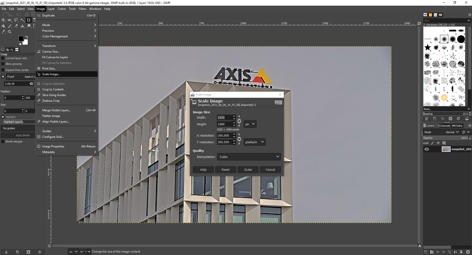
Set max colors in GIMP
The screenshots below illustrate how to set max color in an image using GIMP. Note that the amount of colors has to be set in Image > Mode > Indexed. When done, switch back to Image > Mode > RGB.
Note: If transparency is to be used, make sure to use the pipette tool to check which color the transparent part has after max colors have been set.

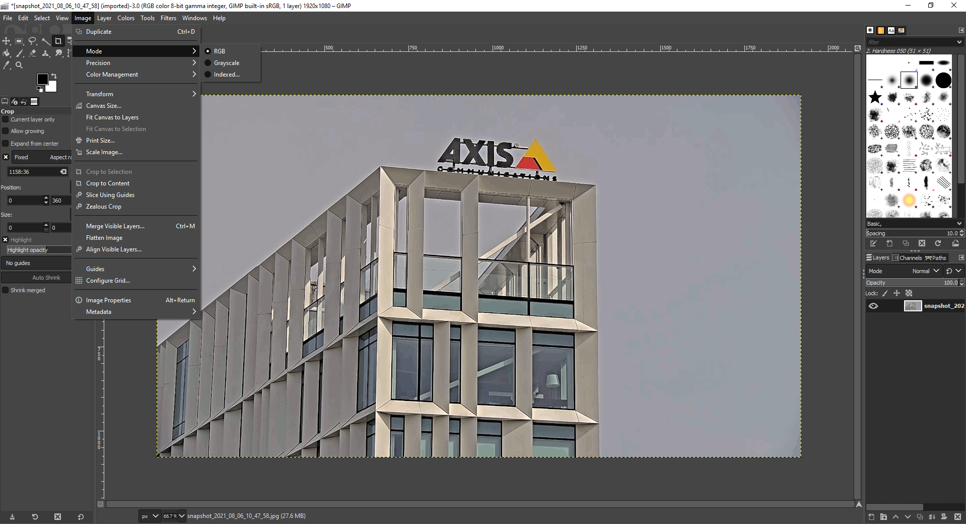
Export 24-bit bmp file in GIMP
The screenshots below illustrate how to export an image as a 24-bit bitmap image.
Send mail
AXIS OS devices support sending mail to various mail services through the built-in event system. While you can customize the settings, some public mail server choices are pre-configured. When using public mail services such as Gmail, Yahoo etc. you are limited to the requirements of their services. From May 30, 2022, Google (and thus the Gmail mailing service) will no longer support the use of third-party apps or devices which ask you to sign in to your Google account using only your username and password. This means that AXIS OS devices will not be able to send mail using a Gmail address as sender without using a Google App Password. Using a Gmail address as a receiver will still work after this date without additional configuration. Further more, Microsoft will no longer support Basic authentication from Dec 30, 2022. This means Hotmail, Outlook etc will stop to work if using basic authentication. Microsoft don’t have their own solution for this.
(C) 2022 Axis Communications AB. AXIS COMMUNICATIONS, AXIS, ARTPEC and VAPIX are registered trademarks of Axis AB in various jurisdictions. All other trademarks are the property of their respective owners.