About your device
AXIS Camera Station S11 Recorder series consist of out-of-the-box ready rack servers and work stations validated for reliable high-definition surveillance up to 4K. For quick and easy installation, the recorder series is preconfigured and preloaded with AXIS Camera Station video management software including licenses plus all necessary system software. The system configuration can easily be imported from AXIS Site Designer, and AXIS Camera Station lets you take full advantage of Axis wide range of video surveillance devices. With redundant enterprise-grade hard disks, operating system stored on solid-state drive (SSD), the recorder series provides high-performance and reliability for your system.
Get started
The standard workflow to configure an AXIS Camera Station recorder is:
Configure Windows®. We recommend to:
Update Windows® to the latest version. See Update Windows®
Create a standard user account. See Create a user account
Update AXIS Camera Station to the latest version.
If your system is online: open the AXIS Recorder Toolbox app and click Update AXIS Camera Station.
If your system is offline: go to axis.com and download the latest version.
Register you AXIS Camera Station licenses.
Connect your system to the AXIS Camera Station mobile viewing app. See Configure AXIS Secure Remote Access
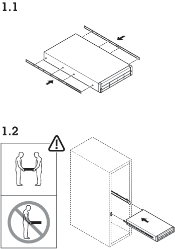
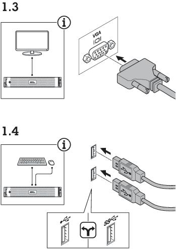
Install your device
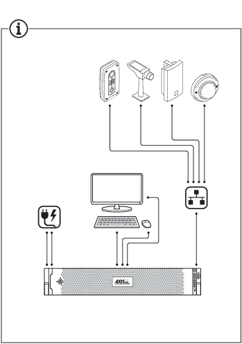
Configure your device
First-time configuration
After you have configured Windows®, AXIS Recorder Toolbox is opened automatically and you are guided through the first-time configuration wizard. In this wizard, you can configure several basic and necessary settings before you manage your device in AXIS Recorder Toolbox.
Change the computer name if you want and click Next.
Under Date and time, configure the following settings and click Next.
Select a time zone.
To set up an NTP server, select NTP server and enter the NTP server address.
To set manually, select Manual and select a date and time.
Under Network settings, configure the following settings and click Next.
Use automatic IP settings (DHCP) and Use automatic DNS settings are turned on by default.
If your device is connected to a network with a DHCP server, the assigned IP address, subnet mask, gateway, and preferred DNS are automatically displayed.
If your device is not connected to a network or there is no DHCP server available, enter the IP address, subnet mask, gateway, and preferred DNS manually depending on the network requirements.
Click Finish. If you have changed the computer name, AXIS Recorder Toolbox will prompt you to restart the device.
Configure AXIS Camera Station Pro
Before you start:
Configure your network depending on your installation. See Network configuration.
Configure your server ports if needed. See Server port configuration.
Consider security issues. See Security considerations.
After necessary configurations, you can start to work with AXIS Camera Station Pro:
Start the video management system
Double-click the AXIS Camera Station Pro client icon to start the client. When you start the client for the first time, it attempts to log in to the AXIS Camera Station Pro server installed on the same computer as the client.
You can connect to multiple AXIS Camera Station Pro servers in different ways.
Add devices
The first time you start AXIS Camera Station S1148 Recorder, the Add devices page opens and searches the network for devices to add.
Select the devices you want to add from the list. If you can’t find a device, click Manual search or type to filter.
Click Add.
Click Close to skip configuration and continue later. To continue with the configuration now:
Choose Quick configuration or Site Designer configuration. See for more information.
Select Add image overlay for date, time, and text to add overlays to any Axis cameras that don’t already have one.
Click Next.
Select your Recording method preference.
Click Next.
Choose your Retention time and Recording storage, and click Finish to apply the configuration.
Configure recording method
Go to Configuration > Recording and events > Recording method.
Select a camera.
Turn on Motion detection, or Continuous, or both.
Click Apply.
View live video
Open a Live view tab.
Select a camera to view its live video.
View recordings
Open a Recordings tab.
Select the camera you want to view recordings from.
Add bookmarks
Go to the recording.
In the timeline, zoom in and out and move the timeline to put the marker at your desired position.
Click
 .
.Enter the bookmark name and description. Use keywords to make the bookmark easy to find.
Select Prevent recording deletion to lock the recording.
- Note
To unlock the recording, clear Prevent recording deletion or delete the bookmark.
Click OK to save the bookmark.
Export recordings
Open a Recordings tab.
Select the camera you want to export recordings from.
Click
 to display the selection markers.
Drag the markers to include the recordings that you want to export.
Click
 to open the Export tab.
Click Export...
Play and verify recordings in AXIS File Player
Go to the folder with the exported recordings.
Double-click AXIS File Player.
Click
 to show the recording’s notes.
To verify the digital signature:
Go to Tools > Verify digital signature.
Select Validate with password and enter your password.
Click Verify to see the verification results.
- Note
- A digital signature is different from signed video. Signed video lets you trace a recording back to the camera it came from, so you can verify it wasn't tampered with. See Signed video and the camera’s user manual for more information.
- If stored files don’t have any connection with an AXIS Camera Station database (non-indexed files), you need to convert them to make them playable in AXIS File Player. Contact Axis Technical support for help converting your files.
Network configuration
Configure proxy or firewall settings before using AXIS Camera Station S1148 Recorder if the client, server, and connected network devices are on different networks.
Client proxy settings
If a proxy server is between the client and the server, configure the proxy settings in Windows on the client computer. Contact Axis support for more information.
Server proxy settings
If the proxy server is between the network device and the server, you must configure the proxy settings in Windows on the server. Contact Axis support for more information.
NAT and Firewall
When a NAT or firewall separates the client and the server, configure it to ensure that the HTTP port, TCP port, and streaming port specified in AXIS Camera Station S1148 Recorder Service Control can pass through. Contact your network administrator for help.
Server port configuration
The AXIS Camera Station S1148 Recorder server uses ports 55752 (HTTP), 55754 (TCP), 55756 (mobile communication), and 55757 (mobile streaming) for communication between the server and the client. You can change the ports in AXIS Camera Station Service Control if required.
Security considerations
To prevent unauthorized access to cameras and recordings:
Use strong passwords for all network devices (cameras, video encoders, and auxiliary devices).
Install the AXIS Camera Station S1148 Recorder server, cameras, video encoders, and auxiliary devices on a secure network, separate from the office network. You can install the AXIS Camera Station S1148 Recorder client on a computer on another network, for example, a network with internet access.
Make sure all users have strong passwords.
License a system online
Both the AXIS Camera Station client and the server must have internet connection.
Go to Configuration > Licenses > Management.
Make sure Manage licenses online turns on.
Sign in with your My Axis account.
The license key automatically generates and appears under License keys.
If you purchased license keys separately, enter your license key under Add license key.
Click Add.
In AXIS Camera Station client, make sure your license keys appear under Configuration > Licenses > Keys.
License a system offline
Go to Configuration > Licenses > Management.
Turn off Manage licenses online.
Click Export system file.
Save your system file to a USB flash drive.
Sign in with your My Axis account.
Click Upload system file to upload the system file from your USB flash drive.
The license key automatically generates and shows under License keys.
If you purchased license keys separately, enter your license key under Add license key.
Click Add.
Under License keys, click Download license file and save the file to a USB flash drive.
In AXIS Camera Station client, go to Configuration > Licenses > Management.
Click Import license file and select the license file on your USB flash drive.
Make sure your license keys appear under Configuration > Licenses > Keys.
Manage local Windows® user accounts
Create a user account
To help keep your personal data and information more secure, we recommend that you add a password for each local account.
Once you create a password for a local account, don't forget it. There’s no way to recover a lost password for local accounts.
Go to Settings > Accounts > Other users > Add other user and click Add account.
Click I don’t have this person’s sign-in information.
Click Add a user without a Microsoft account.
Enter a user name, password and password hint.
Click Next and follow the instructions.
Create an administrator account
Go to Settings > Accounts > Other people.
Go to the account you want to change and click Change account type.
Go to Account type and select Administrator.
Click OK.
Restart your device and sign in with the new administrator account.
Create a local user group
Go to Computer Management.
Go to Local Users and Groups > Group.
Right-click Group and select New Group.
Enter a group name and a description.
Add group members:
Click Add.
Click Advanced.
Find the user account(s) you want to add to the group and click OK.
Click OK again.
Click Create.
Delete a user account
When you delete an account you remove the user account from the login screen. You also remove all files, settings and program data stored on the user account.
Go to Settings > Accounts > Other people.
Go to the account you want to remove and click Remove.
Change a user account's password
Log in with an administrator account.
Go to User Accounts > User Accounts > Manage another account in sequence.
You’ll see a list with all user accounts on the device.
Select the user account whose password you would like to change.
Click Change the password.
Enter the new password and click Change password.
Create a password reset disk for a user account
We recommend to create a password reset disk on a USB flash drive. With this, you can reset the password. Without a password reset disk, you can’t reset the password.
If you’re using Windows® 10, or later, you can add security questions to your local account in case you forget your password, so you don't need to create a password reset disk. To do this, got to Start and click Settings > Sign-in options > Update your security questions.
Sign in to your device with a local user account. You can’t create a password reset disk for a connected account.
Plug an empty USB flash drive into your device.
From the Windows® search field, go to Create a password reset disk.
In the Forgotten Password setup assistant, click Next.
Select your USB flash drive and click Next.
Type your current password and click Next.
Follow the onscreen instructions.
Remove the USB flash drive and keep it in a safe placet. You don't have to create a new disk when you change your password even if you change it several times.
Manage AXIS Camera Station Pro user accounts
User permissions
Go to Configuration > Security > User permissions to see the users and groups in AXIS Camera Station S1148 Recorder.
Administrators of the computer that runs the AXIS Camera Station S1148 Recorder server are automatically granted administrator privileges in AXIS Camera Station S1148 Recorder. You can’t change or remove the Administrators group's privileges.
Before you can add a user or group, make sure they’re registered on the local computer or have a Windows® Active Directory user account. To add users or groups, see Add users or groups.
When a user belongs to a group, they receivet the highest role permission assigned to them individually or to the group. For example, a user with access to camera X who also belongs to a group with access to cameras Y and Z has access to all three cameras.
| Indicates the entry is a single user. | |
| Indicates the entry is a group. | |
Name | Username as it appears in the local computer or Active Directory. |
Domain | The domain that the user or group belongs to. |
Role | The access role assigned to the user or group. Possible values: Administrator, Operator, and Viewer. |
Details | Detailed user information as it appears on the local computer or in Active Directory. |
Server | The server that the user or group belongs to. |
Add users or groups
Microsoft Windows® and Active Directory users and groups can access AXIS Camera Station S1148 Recorder. To add a user to AXIS Camera Station S1148 Recorder, you must add users or a group to Windows®.
To add a user in Windows® 10 and 11:
Press the Windows key + X and select Computer Management.
In the Computer Management window, navigate to Local Users and Groups > Users.
Right-click Users and select New User.
In the popup dialog, enter the new user’s details and clear User must change password at next login.
Click Create.
If you use an Active Directory domain, consult your network administrator.
Add users or groups
Go to Configuration > Security > User permissions.
Click Add. The available users and groups appear in the list.
Under Scope, select where to search for users and groups.
Under Show, select to show users or groups. The search results may not appear if there are too many users or groups. Use the filter to narrow the results.
Select the users or groups and click Add.
| Scope | |
|---|---|
Server | Select to search for users or groups on the local computer. |
Domain | Select to search for Active Directory users or groups. |
Selected server | When connected to multiple AXIS Camera Station S1148 Recorder servers, select a server to search for users or groups on that server. |
Configure a user or group
Select a user or group in the list.
Under Role, select Administrator, Operator, or Viewer.
If you selected Operator or Viewer, you can configure the user or group privileges. See User or group privileges.
Click Save.
Remove a user or group
Select the user or group.
Click Remove.
In the pop-up dialog, click OK to remove the user or group.
User or group privileges
There are three roles you can assign to a user or group. For how to define the role for a user or group, see Add users or groups.
- Administrator
- Full access to the entire system, including access to live and recorded video of all cameras, all I/O ports, and views. This role is required to access system configuration.
- Operator
- Select cameras, views, and I/O ports to get access to live and recorded video. An operator has full access to all functionality of AXIS Camera Station S1148 Recorder except system configuration.
- Viewer
- Access to live video of selected cameras, I/O ports, and views. A viewer doesn’t have access to recorded video or system configuration.
Cameras
The following access privileges are available for users or groups with the Operator or Viewer role.
Access | Allow access to the camera and all camera features. |
Video | Allow access to live video from the camera. |
Audio listen | Allow access to listen from the camera. |
Audio speak | Allow access to speak to the camera. |
Manual Recording | Allow starting and stopping recordings manually. |
Mechanical PTZ | Allow access to mechanical PTZ controls. Available only for cameras with mechanical PTZ. |
PTZ priority | Set the PTZ priority. A lower number means a higher priority. No assigned priority is set to |
Views
The following access privileges are available for users or groups with the Operator or Viewer role. You can select multiple views and set the access privileges.
Access | Allow access to the views in AXIS Camera Station S1148 Recorder. |
Edit | Allows editing of views in AXIS Camera Station S1148 Recorder. |
I/O
The following access privileges are available for users or groups with the Operator or Viewer role.
Access | Allow full access to the I/O port. |
Read | Allows viewing the state of the I/O port without changing it. |
Write | Allows changing the state of the I/O port. |
System
You can’t configure grayed-out access privileges in the list. A check mark means the user or group has this privilege by default.
The following access privileges are available for users or groups with the Operator role. Take snapshots is also available for the Viewer role.
Take snapshots | Allows taking snapshots in live view and recording mode. |
Export recordings | Allow exporting recordings. |
Generate incident report | Allow generating incident reports. |
Prevent access to recordings older than | Prevent access to recordings older than the specified number of minutes. Users can’t find these recordings when they search. |
Access alarms, tasks, and logs | Get alarm notifications and allow access to the Alarms and tasks bar and Logs tab. |
Access data search | Allow searching for data to track what happened at the time of an event. |
Add categories to events | Allow adding categories to events in the Recordings tab. |
Remove categories from event | Allow removing categories from events in the Recordings tab. |
Access control
The following access privileges are available for users or groups with the Operator role. Access Management is also available for the Viewer role.
Access control configuration | Allow configuration of doors and zones, identification profiles, card formats, and PIN, encrypted communication, and multi-server. |
Access management | Allow access management and access to the Active Directory settings. |
The following access privileges are available for users or groups with the Viewer role.
System health monitoring
The following access privileges are available for users or groups with the Operator role. Access to system health monitoring is also available for the Viewer role.
Configuration of system health monitoring | Allows configuration of system health monitoring. |
Access to system health monitoring | Allows access to system health monitoring. |
Manage your device
Update Windows®
Windows® periodically checks for updates. When an update is available, your device automatically downloads the update but you've to install it manually.
Recording will be interrupted during a scheduled system restart.
To manually check for updates:
Go to Settings > Windows Update.
Click Check for updates.
Configure Windows® update settings
It is possible to change how and when Windows® do its updates to suit your needs.
All ongoing recordings stop during a scheduled system restart.
Open the Run app.
Go to Windows System > Run, or
Type
gpedit.mscand click OK. The Local Group Policy Editor opens.Go to Computer Configuration > Administrative Templates > Windows Components > Windows Update.
Configure the settings as required, see example.
Example
To automatically download and install updates without any user interaction and have the device restart, if necessary, at out of office hours, use the following configuration:
Open Always automatically restart at the scheduled time and select:
Enabled
The restart timer will give users this much time to save their work (minutes): 15.
Click OK.
Open Configure Automatic Updates and select:
Enabled
Configure Automatic updates: Auto download and schedule the install
Schedule Install day: Every Sunday
Schedule Install time: 00:00
Click OK.
Open Allow Automatic Updates immediate installation and select:
Enabled
Click OK.
Change the RAID
Changing the RAID deletes all data from your disks.
Boot Lifecycle Controller:
Power on your device.
When you see the AXIS splash screen, press F10.
In the Lifecycle Controller, go to Hardware Configuration > Configuration Wizards and select RAID Configuration.
Select the RAID Controller on which you want to have the RAID created. Details of any virtual disk(s) available on the selected controller will be shown in the table displayed on the page below the controller list. Foreign Configuration will be displayed if there are any foreign or uninitialized HDD(s) available on the server.
- Note
- Clear foreign configuration clears all the foreign HDDs available on the RAID controller selected.
- Ignore foreign Configuration ignores the foreign HDDs available on the RAID controller while creating the RAID.
Clear or ignore foreign HDDs and uninitialized HDDs.
If you want, you can initialize the uninitialized disks:
In the list of all non-RAID (uninitialized) HDDs, select the HDDs you want to convert to RAID capable (initialize) and click Next to initialize them.
Select the corresponding option on the Configuration Wizards: RAID Configuration page.
Select a RAID level. The default settings are:
S1148 24 TB: RAID 5
S1148 64 TB: RAID 5
S1148 140 TB: RAID 6
S1132: RAID 5
Select the physical disks from the table and click Next.
If the you’ve selected Ignore foreign configuration, the foreign HDDs are not displayed in the table.
Enter the virtual disk attributes.
Click Next.
Review the settings and click Finish.
Lifecycle Controller displays a message to indicate that all the current data about the virtual disks available on the controller will be lost. Click OK to continue.
Click OK and Finish.
Exit the wizard and reboot the system.
Add a hard drive
This section explains how to install a hard drive, how you add it to the existing RAID array, and what you must configure in Windows®.
You can only add a hard drive to S1148 24 TB and S1148 64 TB.
The following instructions are to be used when adding additional storage in to the AXIS S11-series. These instructions are as is, and Axis Communications AB takes no responsibility for loss of data and/or configuration during these steps. The standard precautions should be taken to backup data that is business critical. The following procedure of expanding storage will not be supported by Axis Technical Support.
To avoid electrostatic discharge, it is recommended that you always use a static mat and static strap while working on components in the interior of the system.
Warranty
Axis Communications AB grants to the original purchaser (the distributor) a hardware warranty for the network video recorders mentioned above. Detailed information about warranty is available at: axis.com/support/warranty-and-rma/warranty.
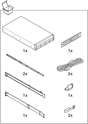
Workflow
Remove the bezel
Locate the bezel key.
Unlock the bezel by using the key.
Slide the release latch up and pull the left end of the bezel.
Unhook the right end and remove the bezel.
Install the hard drive
- Use only hard drives that have been tested and approved for use with AXIS S1148.
- When installing a hard drive, ensure that the adjacent drives are fully installed. Inserting a hard drive carrier and attempting to lock its handle next to a partially installed carrier can damage the partially installed carrier's shield spring and make it unusable
- Combining SAS and SATA hard drives in the same RAID volume is not supported.
Press the release button and slide the hard disk blank out of the hard drive slot.
Install a hard drive in the hard drive carrier.
Press the release button on the front of the hard drive carrier and open the hard drive carrier handle.
Insert the hard drive carrier into the hard drive slot until the carrier connects with the backplane
Close the hard drive carrier handle to lock the hard drive in place.
Add new drive to RAID array
Changing the RAID deletes all data from your disks.
Boot Lifecycle Controller:
Power on your device.
When you see the AXIS splash screen, press F10.
In the Lifecycle Controller, go to Hardware Configuration > Configuration Wizards and select RAID Configuration.
Select the RAID Controller on which you want to have the RAID created. Details of any virtual disk(s) available on the selected controller will be shown in the table displayed on the page below the controller list. Foreign Configuration will be displayed if there are any foreign or uninitialized HDD(s) available on the server.
- Note
- Clear foreign configuration clears all the foreign HDDs available on the RAID controller selected.
- Ignore foreign Configuration ignores the foreign HDDs available on the RAID controller while creating the RAID.
Clear or ignore foreign HDDs and uninitialized HDDs.
If you want, you can initialize the uninitialized disks:
In the list of all non-RAID (uninitialized) HDDs, select the HDDs you want to convert to RAID capable (initialize) and click Next to initialize them.
Select the corresponding option on the Configuration Wizards: RAID Configuration page.
Select a RAID level. The default settings are:
S1148 24 TB: RAID 5
S1148 64 TB: RAID 5
S1148 140 TB: RAID 6
S1132: RAID 5
Select the physical disks from the table and click Next.
If the you’ve selected Ignore foreign configuration, the foreign HDDs are not displayed in the table.
Enter the virtual disk attributes.
Click Next.
Review the settings and click Finish.
Lifecycle Controller displays a message to indicate that all the current data about the virtual disks available on the controller will be lost. Click OK to continue.
Click OK and Finish.
Exit the wizard and reboot the system.
Configure Windows®
Right-click the Windows®-symbol at the Start menu and select Disk Management.
Go to Action > All Tasks > Extend Volume. The Extend Volume Wizard starts.
Click Next.
Select the disk that has unused space and click Next. Usually this disk is selected by the wizard.
Click Finish.
Disk Management now shows the extend volume and your system is ready to use the extended volume.
Troubleshooting
Check the current BIOS version
When you troubleshoot a device, always check the current BIOS version. If your device doesn't have the latest version, we recommend to upgrade. The latest version may contain a correction that fixes your problem.
To check the current BIOS:
Power on the device.
Wait until you see the Axis splash screen. You’ll see the version number above the splash screen.
Upgrade BIOS
We recommend to keep the BIOS up to date.
If you don’t have access to Windows®: update package instructions for EFI
Go to the support pages on dell.com and enter your service tag. Go to Drivers & Downloads and download the .efi file.
Copy the file to a USB device.
Plug in the USB device and press F11 during POST to enter BIOS Boot Manager.
Go to System Utilities menu > BIOS Update File Explorer.
Select the USB device and navigate through the directory contents to find the executable (.efi).
Launch the executable and follow the instructions provided by the flash utility.
If you have access to Windows®: update package instructions for Windows® Dup
Browse to the location where you downloaded the file and double-click the new file.
Read over the release information in the dialog window.
Download and install any prerequisites identified in the dialog window before proceeding.
Install any necessary Embedded Systems Management firmware prior to this BIOS update.
Click Install.
Follow the onscreen instructions.
Run diagnostics
Running diagnostics help you to identify the cause for a system issue. The diagnostics test your system hardware without requiring additional equipment or risking data loss.
While the system is booting, press F11 to enter Boot Manager.
Alternatively, press F10 to enter Lifecycle Controller.
Go to Hardware Diagnostics and click Run Hardware Diagnostics.
Note the error code and contact Axis technical support.
Perform a system recovery
If the device has had a complete system failure, you must use a recovery image to recreate the Windows® system. To download the AXIS Recovery Kit, contact Axis technical support and supply the serial number of your device.
Download the AXIS Recovery Kit and AXIS ISO to USB Tool.
Insert a USB drive into your computer.
Use a USB drive with a minimum of 16 GB to 32 GB.
The USB drive will be formatted, and all existing data will be erased.
Run the AXIS ISO to USB Tool and follow the onscreen instructions.
Writing data to the USB drive takes approximately 10 to 15 min. Don’t remove the USB drive until the process is complete.
After the ISO to USB tool is complete, take the USB drive and plug it into your device.
Start your device.
When you see the AXIS splash screen, press F11.
Click One-shot UEFI Boot Menu.
Navigate to your USB drive and press enter. The system boots into the AXIS Recovery Kit.
Click Reinstall Operating System.
The recovery takes roughly 10 to 15 min to complete. You find detailed instructions in the download for the recovery kit.
Create a technical support report
The Export Tech Support Report feature allows you to export the technical support report to a USB drive or a network share (CIFS/NFS). In the report you can collect the following data:
Hardware
RAID controller logs
To create a technical support report:
During Power-on-self-test (POST), press F10 to start Lifecycle Controller.
Go to Hardware Diagnostics > Export Tech Support Report.
Read the terms and conditions and click Next.
You must accept the terms and conditions to allow technical support to use the technical support report data.
Select the data options which you want to include in the technical support report and click Next.
Enter the required export settings information and click Next.
To export the report to a USB drive: select the USB drive option and then select the name of the USB Drive and enter the file path details to where the report is to export.
To export the report to NFS: select the NFS option and enter the required information.
To export the report to CIFS: select the CIFS option and enter the required information.
Click Test Network Connection to verify if the Lifecycle Controller can connect to the IP address that is provided. By default, it pings the Gateway IP, DNS Server IP, host IP and Proxy IP.
Verify your selection and click Finish.
Lifecycle Controller retrieves the selected report data and exports the report file to the specified location. This can take a few minutes.
Enable IDRAC
You can set up the IP address or use the default iDRAC IP address 192.168.0.120 to configure initial network settings, including setting up DHCP or the static IP for iDRAC. By default, the dedicated iDRAC network card is disabled. The iDRAC is sharing the network card on LOM 1 (LAN on Motherboard). In the case of blade servers, the iDRAC network interface is disabled by default.
To set up iDRAC IP using iDRAC settings utility:
Turn on the managed system.
Press F2 during Power-on Self-test (POST).
In the System Setup Main Menu page, click iDRAC Settings.
Click Network.
Enable NIC.
Specify the other network settings.
Click Back, Finish, and then Yes. The network information is saved and the system reboots.
You can open the iDRAC webpage from any supported browser. The default login information is:
Username: root
Password: available on the back of the information tag.
After you configure iDRAC IP address, ensure that you change the default user name and password after setting up the iDRAC IP address.
If there is any access issue:
- Try to ping the iDRAC IP to check that the network configuration has been replied.
- Check which LOM (network card) has been selected in the iDRAC network settings. The LOM can be shared with the server network cards or use the dedicated iDRAC NIC's.
Troubleshoot the power supply unit
After installing a power supply unit, allow several seconds for the system to recognize the power supply unit and determine if it the power supply works properly.
Ensure that no loose connections exist. For example, loose power cables.
Ensure that the power supply handle LED indicates that the power supply is working properly.
Check the status of the power indicator on the power supply unit.
If the power indicator is green, reset the power supply unit. If this does not fix the issue, test the system with a good power supply unit.
If the power indicator is amber, this indicates a power supply unit fault condition. Replace the power supply unit with a good power supply unit and check the indicator status.
If the issue is resolved, consider replacing the power supply unit.
If you have a redundant power supply configuration, ensure that both power supply units are of the same type and wattage. You may have to upgrade to a higher wattage PSU.
Ensure that you use only power supply units with the Extended Power Performance (EPP) label on the back.
Reset the power supply unit.
If the problem persists, contact Axis Technical Support.
Troubleshoot memory errors
Upgrade the BIOS to the latest version.
If the errors persist, contact Axis technical support.
Troubleshoot AXIS Camera Station Pro
For information about how to troubleshoot AXIS Camera Station Pro, go to the AXIS Camera Station Pro user manual.
Product overview
Front and rear sides
S1148 24 TB
S1148 64 TB
S1148 140TB
- i LED
- Drive activity LED
- Drive status LED
- Opening button
- USB 3.1 Type-C
- USB 2.1
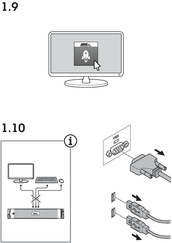
- System power LED/power button
- VGA
- System identification button
- System status indicator cable port
- VGA
- USB 3.1
- iDRAC9 dedicated network port
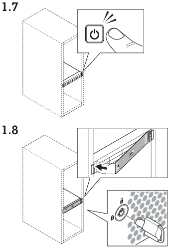
- Ethernet (RJ45) 1 GbE
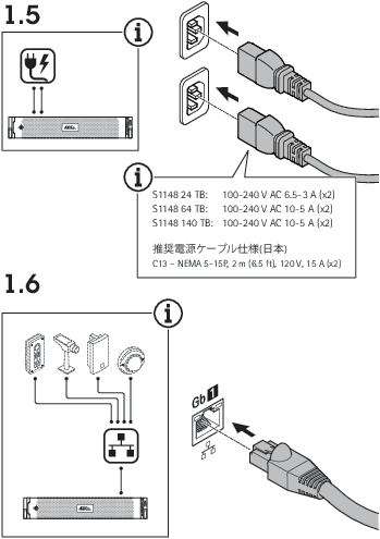
- Power connector
- Power cable lock
Specifications
System health and ID indicators
| LED | Description | Action |
| Blue solid | The system is turned on, system is healthy and system ID mode is not active. | Press the system health and system ID button to switch to system ID mode. |
| Blue blinking | The system ID mode is active. | Press the system health and system ID button to switch to system health mode. |
| Amber solid | The system is in fail-safe mode. | - |
| Amber blinking | The system is experiencing a fault. | Check the system event log for the specific error message. |
IDRAC quick sync 2 indicator
| LED | Description | Action |
| Off (default state) | The iDRAC Quick Sync 2 feature is turned off. | Press the iDRAC Quick Sync 2 button to turn on the iDRAC Quick Sync 2 feature. If the LED fails to turn on, reset the left control panel flex cable and check again. |
| White solid | The iDRAC Quick Sync 2 is ready to communicate. | Press the iDRAC Quick Sync 2 button to turn off. If the LED fails to turn off, restart the system. |
| Blinks white rapidly | Data transfer activity | - |
| Blinks white slowly | Firmware update is in progress. | - |
| Blinks white five times rapidly and then turns off | The iDRAC Quick Sync 2 feature is disabled. | Check if iDRAC Quick Sync 2 feature is configured to be disabled by iDRAC. |
| Amber solid | The system is in fail-safe mode. | Restart the system. |
| Amber blinking | The iDRAC Quick Sync 2 hardware is not responding properly. | Restart the system. |
NIC indicators
| LED | Description |
| Link and activity indicators are off | The NIC is not connected to the network. |
| Link indicator is green and activity indicator is blinking green | The NIC is connected to a valid network at its maximum port speed and data is being sent or received. |
| Link indicator is amber and activity indicator is blinking green | The NIC is connected to a valid network at less than its maximum port speed and data is being sent or received. |
| Link indicator is green and activity indicator is off | The NIC is connected to a valid network at its maximum port speed and data is not being sent or received. |
| Link indicator is amber and activity indicator is off | The NIC is connected to a valid network at less that its maximum port speed and data is not being sent or received |
| Link indicator is blinking green and activity is off | NIC identify is enabled through the NIC configuration utility. |
Power supply unit indicators
| LED | Description |
| Green | A valid power source is connected to the PSU and the PSU is operational. |
| Blinking amber | Indicates a problem with the PSU |
| Not illuminated | Power is not connected. |
| Blinking green | When the firmware of the PSU is being updated, the PSU handle blinks green. CAUTION: Do not disconnect the power cord or unplug the PSU when updating firmware. If firmware update is interrupted the PSUs do not function. |
| Blinking green and turns off | When hot-plugging a PSU, the PSU handle blinks green five times at a rate of 4Hz and turns off. This indicates a PSU mismatch with respect to efficiency, features set, health status, or supported voltage. CAUTION
|
Power indicators
| LED | Description |
| Green | A valid power source is connected to the PSU and the PSU is operational. |
| Blinking amber | Indicates a problem with the PSU. |
| Not illuminated | Power is not connected. |
| Blinking green | When hot-plugging a PSU, the PSU indicator blinks green. This indicates that there is a PSU mismatch with respect to efficiency, feature set, health status, or supported voltage. CAUTION
|
Hard drive indicators
| LED | Description |
| Flashes green twice per second | Identifying drive or preparing for removal. |
| Off | Drive ready for insertion or removal. Note The drive status indicator remains off until all hard drives are initialized after the system is turned on. Drives are not ready for removal during this time. |
| Flashes green, amber and then turns off | Predicted drive failure. |
| Flashes amber four times per second | Drive has failed. |
| Flashes green slowly | Drive is rebuilding. |
| Steady green | Drive is online. |
| Flashes green for 3 s, amber for 3 s, and then turns off after 6 s | Rebuild stopped. |
Need more help?
Useful links
Contact support
If you need more help, go to axis.com/support.