To find Axis devices on the network and assign them IP addresses in Windows®, use AXIS IP Utility or AXIS Device Manager. Both applications are free and can be downloaded from axis.com/support.
Axis devices send the initially set password in clear text over the network. To protect your device after the first login, set up a secure and encrypted HTTPS connection and then change the password.
The device password is the primary protection for your data and services. Axis devices do not impose a password policy as they may be used in various types of installations.
To protect your data we strongly recommend that you:
Use a password with at least 8 characters, preferably created by a password generator.
Don’t expose the password.
Change the password at a recurring interval, at least once a year.
Set a new password for the root account
The default administrator username is root. There’s no default password for the root account. You set a password the first time you log in to the device.
Type a password. Follow the instructions about secure passwords. See Secure passwords.
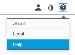
You can access the built-in help from the device’s webpage. The help provides more detailed information on the device’s features and their settings.
You can access the built-in help from the camera’s webpage. The help provides more detailed information on the product’s features and their settings.
Replace the lens
Stop all recordings and disconnect power from the product.
Disconnect the lens cable and remove the standard lens.
Attach the new lens and connect the lens cable.
Reconnect the power.
Log in to the product’s webpage, go to the Image tab and then select the P-Iris lens you have installed.
Note
If you use a DC iris lens, select Generic DC Iris.
For the changes to take effect, you need to restart the device. Go to System > Maintenance and click Restart.
Adjust the zoom and focus.
Hide parts of the image with privacy masks
You can create one or several privacy masks to hide parts of the image.
Go to Video > Privacy masks.
Click .
Click the new mask and type a name.
Adjust the size and placement of the privacy mask according to your needs.
To change the color for all privacy masks, click Privacy masks and select a color.
See also
Reduce noise in low-light conditions
Note
Low-light settings are only available for the visual channel.
To reduce noise in low-light conditions, you can adjust one or more of the following settings:
Adjust the trade-off between noise and motion blur. Go to Video > Image > Exposure and move the Blur-noise trade-off slider toward Low noise.
Set the exposure mode to automatic.
Note
A high max shutter value can result in motion blur.
To slow down the shutter speed, set max shutter to the highest possible value.
Note
When you reduce the max gain, the image can become darker.
Set the max gain to a lower value.
If possible, open the aperture.
Reduce sharpness in the image, under Video > Image > Appearance.
If the above settings do not improve the image sufficiently, change to a lens with a lower f-value.
Select exposure mode
Note
Exposure modes are only available for the visual channel.
To improve image quality for specific surveillance scenes, use exposure modes. Exposure modes lets you control aperture, shutter speed, and gain. Go to Video > Image > Exposure and select between the following exposure modes:
For most use cases, select Automatic exposure.
For fast moving objects that require a fast or fixed shutter, select Automatic aperture.
To maintain a longer depth of field or focus range, select Automatic shutter.
For environments with certain artificial lighting, for example fluorescent lighting, select Flicker-free.
Select the same frequency as the power line frequency.
For environments with certain artificial light and bright light, for example outdoors with fluorescent lighting at night and sun during daytime, select Flicker-reduced.
Select the same frequency as the power line frequency.
If you need full control of all parameters, select Manual. This is mostly useful for scenes with little change in lighting.
To lock the current exposure settings, select Hold current.
Maximize the details in an image
Important
If you maximize the details in an image, the bitrate will probably increase and you might get a reduced frame rate.
Make sure to select the capture mode that has the highest resolution.
Go to Video > Stream > General and set the compression as low as possible.
Below the live view image, click and in Video format, select MJPEG.
Go to Video > Stream > Zipstream and select Off.
Monitor long and narrow areas
Use corridor format to better utilize the full field of view in a long and narrow area, for example a staircase, hallway, road, or tunnel.
Depending on your device, turn the camera or the 3-axis lens in the camera 90° or 270°.
If the device doesn’t have automatic rotation of the view, go to Video > Installation.
Rotate the view 90° or 270°.
Verify the pixel resolution
To verify that a defined part of the image contains enough pixels to, for example, recognize the face of a person, you can use the pixel counter.
Go to Video > Image and click .
Click for Pixel counter.
In the camera’s live view, adjust the size and position of the rectangle around the area of interest, for example where you expect faces to appear.
You can see the number of pixels for each of the rectangle’s sides, and decide if the values are enough for your needs.
View area
A view area is a cropped part of the full view. You can stream and store view areas instead of the full view to minimize bandwidth and storage needs. If you enable PTZ for a view area, you can pan, tilt and zoom within it. By using view areas you can remove parts of the full view, for example, the sky.
A view area is a cropped part of the full view. You can stream and store the view area instead of the full view to minimize bandwidth and storage needs. If you enable PTZ for the view area, you can pan, tilt and zoom within it. By using a view area you can remove parts of the full view, for example, the sky.
When you set up a view area, we recommend you to set the video stream resolution to the same size as or smaller than the view area size. If you set the video stream resolution larger than the view area size it implies digitally scaled up video after sensor capture, which requires more bandwidth without adding image information.
Handle scenes with strong backlight
Dynamic range is the difference in light levels in an image. In some cases the difference between the darkest and the brightest areas can be significant. The result is often an image where either the dark or the bright areas are visible. Wide dynamic range (WDR) makes both dark and bright areas of the image visible.
Image without WDR.Image with WDR.
Note
WDR can cause artifacts in the image.
WDR may not be available for all capture modes.
Go to Video > Image > Wide dynamic range.
Turn on WDR.
Use the Local contrast slider to adjust the amount of WDR.
Use the Tone mapping slider to adjust the amount of WDR.
To set the amount of WDR, select Low, Medium or High from the WDR level list.
If you still have problems, go to Exposure and adjust the Exposure zone to cover the area of interest.
Overlays are not included in the video stream when using SIP calls.
Note
Image and text overlay will not be displayed on video stream over HDMI.
Note
Image and text overlay will not be displayed on video stream over SDI.
Overlays are superimposed over the video stream. They are used to provide extra information during recordings, such as a timestamp, or during product installation and configuration. You can add either text or an image.
The video streaming indicator is another type of overlay. It shows you that the live view video stream is live.
Show a text overlay in the video stream when the device detects an object
This example explains how to display the text “Motion detected” when the device detects an object.
Make sure that AXIS Object Analytics is running:
Make sure that AXIS Video Motion Detection is running:
Go to Apps > AXIS Object Analytics.
Go to Apps > AXIS Video Motion Detection.
Start the application if it is not already running.
Make sure you have set up the application according to your needs.
Add the overlay text:
Go to Video > Overlays.
Under Overlays, select Text and click .
Enter #D in the text field.
Choose text size and appearance.
To position the text overlay, click and select an option.
Create a rule:
Go to System > Events and add a rule.
Type a name for the rule.
In the list of conditions, under Application, select Object Analytics.
In the list of conditions, under Application, select VMD4.
In the list of actions, under Overlay text, select Use overlay text.
Select a video channel.
In Text, type “Motion detected”.
Set the duration.
Click Save.
Note
If you update the overlay text it will be automatically updated on all video streams dynamically.
Bitrate control
Bitrate control helps you to manage the bandwidth consumption of your video stream.
Variable bitrate (VBR)Variable bitrate allows the bandwidth consumption to vary depending on the level of activity in the scene. The more activity, the more bandwidth you need. With variable bitrate you are guaranteed constant image quality, but you need to make sure you have storage margins.
Maximum bitrate (MBR)Maximum bitrate lets you set a target bitrate to handle bitrate limitations in your system. You might see a decline in image quality or frame rate as the instantaneous bitrate is kept below the specified target bitrate. You can choose to prioritize either image quality or frame rate. We recommend that you configure the target bitrate to a higher value than the expected bitrate. This gives you a margin in case there is a high level of activity in the scene.
Target bitrate
Average bitrate (ABR)With average bitrate, the bitrate is automatically adjusted over a longer period of time. This is so you can meet the specified target and provide the best video quality based on your available storage. Bitrate is higher in scenes with a lot of activity, compared to static scenes. You are more likely to get better image quality when in scenes with a lot of activity if you use the average bitrate option. You can define the total storage required to store the video stream for a specified amount of time (retention time) when image quality is adjusted to meet the specified target bitrate. Specify the average bitrate settings in one of the following ways:
To calculate the estimated storage need, set the target bitrate and the retention time.
To calculate the average bitrate, based on available storage and required retention time, use the target bitrate calculator.
Target bitrate
Actual average bitrate
You can also turn on maximum bitrate and specify a target bitrate within the average bitrate option.
Target bitrate
Actual average bitrate
Video compression formats
Decide which compression method to use based on your viewing requirements, and on the properties of your network. The available options are:
Motion JPEG
Note
To ensure support for the Opus audio codec, the Motion JPEG stream is always sent over RTP.
Motion JPEG, or MJPEG, is a digital video sequence that is made up of a series of individual JPEG images. These images are then displayed and updated at a rate sufficient to create a stream that shows constantly updated motion. For the viewer to perceive motion video the rate must be at least 16 image frames per second. Full motion video is perceived at 30 (NTSC) or 25 (PAL) frames per second.
The Motion JPEG stream uses considerable amounts of bandwidth, but provides excellent image quality and access to every image contained in the stream.
H.264 or MPEG-4 Part 10/AVC
Note
H.264 is a licensed technology. The Axis product includes one H.264 viewing client license. To install additional unlicensed copies of the client is prohibited. To purchase additional licenses, contact your Axis reseller.
H.264 can, without compromising image quality, reduce the size of a digital video file by more than 80% compared to the Motion JPEG format and by as much as 50% compared to older MPEG formats. This means that less network bandwidth and storage space are required for a video file. Or seen another way, higher video quality can be achieved for a given bitrate.
H.265 or MPEG-H Part 2/HEVC
H.265 can, without compromising image quality, reduce the size of a digital video file by more than 25% compared to H.264.
Note
H.265 is licensed technology. The Axis product includes one H.265 viewing client license. Installing additional unlicensed copies of the client is prohibited. To purchase additional licenses, contact your Axis reseller.
Most web browsers don’t support H.265 decoding and because of this the camera doesn’t support it in its web interface. Instead you can use a video management system or application supporting H.265 decoding.
Reduce bandwidth and storage
Important
Reducing the bandwidth can result in loss of details in the image.
Go to Video > Stream.
Click in the live view.
Select Video format H.264.
Go to Video > Stream > General and increase Compression.
Go to Video > Stream > Zipstream and do one or more of the following:
Select the Zipstream Strength that you want to use.
Note
The Zipstream settings are used for both H.264 and H.265.
Turn on Dynamic FPS.
Turn on Dynamic GOP and set a high Upper limit GOP length value.
Note
Most web browsers don’t support H.265 decoding and because of this the device doesn’t support it in its web interface. Instead you can use a video management system or application that supports H.265 decoding.
Set up network storage
To store recordings on the network, you need to set up your network storage.
Go to System > Storage.
Click Add network storage under Network storage.
Type the IP address of the host server.
Type the name of the shared location on the host server under Network share.
Type the username and password.
Select the SMB version or leave it on Auto.
Select Add share even if connection fails if you experience temporary connection issues, or if the share is not yet configured.
Click Add.
Add audio to your recording
Note
To connect the audio device, this product requires a multicable.
Turn on audio:
Go to Video > Stream > Audio and include audio.
If the device has more than one input source, select the correct one in Source.
Go to Audio > Device settings and turn on the correct input source.
If you make any changes to the input source, click Apply changes.
Edit the stream profile that is used for the recording:
Go to System > Stream profiles and select the stream profile.
Select Include audio and turn it on.
Click Save.
Record and watch video
Record video directly from the camera
Go to Video > Image.
To start a recording, click .
If you haven’t set up any storage, click and . For instructions on how to set up network storage, see Set up network storage
To stop recording, click again.
Watch video
Go to Recordings.
Click for your recording in the list.
Set up rules for events
You can create rules to make your device perform an action when certain events occur. A rule consists of conditions and actions. The conditions can be used to trigger the actions. For example, the device can start a recording or send an email when it detects motion, or show an overlay text while the device is recording.
You can create rules to make your device perform actions when certain events occur. A rule consists of conditions and actions. The conditions can be used to trigger the actions. For example, the device can play an audio clip according to a schedule or when it receives a call, or send an email if the device changes IP address.
Go to System > Events and add a rule. The rule defines when the device will perform certain actions. You can set up rules as scheduled, recurring, or manually triggered.
Enter a Name.
Select the Condition that must be met to trigger the action. If you specify more than one condition for the rule, all of the conditions must be met to trigger the action.
Select which Action the device should perform when the conditions are met.
Note
If you make changes to an active rule, the rule must be turned on again for the changes to take effect.
Note
If you change the definition of a stream profile that is used in a rule, then you need to restart all the rules that use that stream profile.
Record video when the camera detects an object
This example explains how to set up the camera to start recording to the SD card when the camera detects an object. The recording will include five seconds before detection and one minute after detection ends.
Before you start:
Make sure you have an SD card installed.
Make sure that AXIS Object Analytics is running:
Make sure that AXIS Video Motion Detection is running:
Go to Apps > AXIS Object Analytics.
Go to Apps > AXIS Video Motion Detection.
Start the application if it is not already running.
Make sure you have set up the application according to your needs.
Create a rule:
Go to System > Events and add a rule.
Type a name for the rule.
In the list of conditions, under Application, select Object Analytics.
In the list of conditions, under Application, select VMD4.
In the list of actions, under Recordings, select Record video while the rule is active.
In the list of storage options, select SD_DISK.
Select a camera and a stream profile.
Set the prebuffer time to 5 seconds.
Set the postbuffer time to 1 minute.
Click Save.
Applications
With applications you can get more out of your Axis device. AXIS Camera Application Platform (ACAP) is an open platform that makes it possible for third parties to develop analytics and other applications for Axis devices. Applications can be preinstalled on the device, available for download for free, or for a license fee.
To find the user manuals for Axis applications, go to help.axis.com.
Note
We recommended running one application at a time.
Several applications can run at the same time but some applications might not be compatible with each other. Certain combinations of applications might require too much processing power or memory resources when run in parallel. Verify that the applications work together before deployment.
Avoid running applications when the built-in motion detection is active.
Applications are supported on channel 1.
Important
AXIS 3D People Counter is an application that is embedded in the device. We don’t recommend you to run any other applications on this device since it can affect the performance of the AXIS 3D People Counter.
How to download and install an application
How to activate an application licence code on a device
Troubleshooting
Reset to factory default settings
WARNING
Possibly hazardous optical radiation is emitted from this product. It can be harmful to the eyes. Don’t stare at the operating lamp.
Important
Reset to factory default should be used with caution. A reset to factory default resets all settings, including the IP address, to the factory default values.
Note
The camera has been preconfigured with AXIS License Plate Verifier. If you reset to factory default, you need to reinstall the license key. See .
Note
For products with multiple IP addresses channel 1 will have the address 192.168.0.90, channel 2 will have the address 192.168.0.91 and so on.
To reset the product to the factory default settings:
Disconnect power from the product.
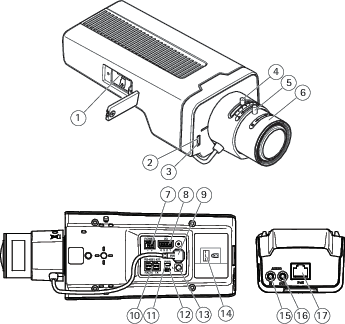
Press and hold the control button while reconnecting power. See Product overview.
Keep the control button pressed for 15–30 seconds until the status LED indicator flashes amber.
Release the control button. The process is complete when the status LED indicator turns green. The product has been reset to the factory default settings. If no DHCP server is available on the network, the default IP address is 192.168.0.90.
Use the installation and management software tools to assign an IP address, set the password, and access the device.
The installation and management software tools are available from the support pages on axis.com/support.
Refocus the product.
Press and hold the control button and the restart button at the same time.
Release the restart button but continue to hold down the control button for 15–30 seconds until the status LED indicator flashes amber.
Release the control button. The process is complete when the status LED indicator turns green. The product has been reset to the factory default settings. If no DHCP server is available on the network, the default IP address is 192.168.0.90.
Use the installation and management software tools to assign an IP address, set the password and access the video stream.
Release the restart button and hold the control button.
Keep the control button pressed until the power LED indicator turns green and the 4 status LED indicators turn amber (this may take up to 15 seconds).
Keep the control button pressed until the power LED indicator turns green and the 6 status LED indicators turn amber (this may take up to 15 seconds).
Release the control button. When the status LED indicators display green (which can take up to 1 minute) the process is complete and the unit has been reset.
The process is now complete. The product has been reset to the factory default settings. If no DHCP server is available on the network, the default IP address is 192.168.0.90-93.
The process is now complete. The product has been reset to the factory default settings. If no DHCP server is available on the network, the default IP address is 192.168.0.90-95.
Use the installation and management software tools to assign the IP addresses, set the password and access the video stream.
Note
To reset a single channel to the original factory default settings, log in to the device’s web interface and use the provided button.
Press and hold the control button and the power button for 15–30 seconds until the status LED indicator flashes amber. See Product overview.
Release the control button but continue to hold down the power button until the status LED indicator turns green.
Release the power button and assemble the product.
The process is now complete. The product has been reset to the factory default settings. If no DHCP server is available on the network, the default IP address is 192.168.0.90.
Using the installation and management software tools to assign an IP address, set the password and access the video stream.
Press and hold the control button and the power button. See Product overview.
Release the power button but continue to hold down the control button for 15–30 seconds until the status LED indicator flashes amber.
Release the control button.
The process is now complete. The product has been reset to the factory default settings. If no DHCP server is available on the network, the default IP address is 192.168.0.90.
Using the installation and management software tools, assign an IP address, set the password and access the video stream.
Disconnect power from the product.
Press and hold the control button while reconnecting power. See Product overview.
Keep the control button pressed for 25 seconds until the status LED indicator turns amber for the second time.
Release the control button. The process is complete when the status LED indicator turns green. The product has been reset to the factory default settings. If no DHCP server is available on the network, the default IP address is 192.168.0.90.
Use the installation and management software tools, assign an IP address, set the password, and access the product.
Disconnect power from the product.
Press and hold the control button while reconnecting power. See Product overview.
Keep the control button pressed for 10 seconds until the status LED indicator turns amber for the second time.
Release the control button. The process is complete when the status LED indicator turns green. The product has been reset to the factory default settings. If no DHCP server is available on the network, the default IP address is 192.168.0.90.
Use the installation and management software tools, assign an IP address, set the password, and access the product.
You can also reset parameters to factory default through the device’s web interface. Go to Maintenance > Factory default and click Default.
Check the current firmware version
Firmware is the software that determines the functionality of network devices. When you troubleshoot a problem, we recommend you to start by checking the current firmware version. The latest firmware version might contain a correction that fixes your particular problem.
To check the current firmware:
Go to the device’s web interface > Status.
See the firmware version under Device info.
Upgrade the firmware
Important
Preconfigured and customized settings are saved when you upgrade the firmware (provided that the features are available in the new firmware) although this is not guaranteed by Axis Communications AB.
Make sure the device remains connected to the power source throughout the upgrade process.
Make sure the cover is attached during upgrade to avoid installation failure.
Note
When you upgrade the device with the latest firmware in the active track, the product receives the latest functionality available. Always read the upgrade instructions and release notes available with each new release before you upgrade the firmware. To find the latest firmware and the release notes, go to axis.com/support/firmware.
Note
Because the database of users, groups, credentials, and other data are updated after a firmware upgrade, the first start-up could take a few minutes to complete. The time required is dependent on the amount of data.
If you can’t find what you’re looking for here, try the troubleshooting section at axis.com/support.
Problems upgrading the firmware
Firmware upgrade failure
If the firmware upgrade fails, the device reloads the previous firmware. The most common reason is that the wrong firmware file has been uploaded. Check that the name of the firmware file corresponds to your device and try again.
Problems after firmware upgrade
If you experience problems after a firmware upgrade, roll back to the previously installed version from the Maintenance page.
Problems setting the IP address
The device is located on a different subnet
If the IP address intended for the device and the IP address of the computer used to access the device are located on different subnets, you cannot set the IP address. Contact your network administrator to obtain an IP address.
The IP address is being used by another device
Disconnect the Axis device from the network. Run the ping command (in a Command/DOS window, type ping and the IP address of the device):
If you receive: Reply from <IP address>: bytes=32; time=10... this means that the IP address may already be in use by another device on the network. Obtain a new IP address from the network administrator and reinstall the device.
If you receive: Request timed out, this means that the IP address is available for use with the Axis device. Check all cabling and reinstall the device.
Possible IP address conflict with another device on the same subnet
The static IP address in the Axis device is used before the DHCP server sets a dynamic address. This means that if the same default static IP address is also used by another device, there may be problems accessing the device.
The device can’t be accessed from a browser
Can’t log in
When HTTPS is enabled, ensure that the correct protocol (HTTP or HTTPS) is used when attempting to log in. You may need to manually type http or https in the browser’s address field.
If the password for the user root is lost, the device must be reset to the factory default settings. See Reset to factory default settings.
The IP address has been changed by DHCP
IP addresses obtained from a DHCP server are dynamic and may change. If the IP address has been changed, use AXIS IP Utility or AXIS Device Manager to locate the device on the network. Identify the device using its model or serial number, or by the DNS name (if the name has been configured).
If required, a static IP address can be assigned manually. For instructions, go to axis.com/support.
Certificate error when using IEEE 802.1X
For authentication to work properly, the date and time settings in the Axis device must be synchronized with an NTP server. Go to System > Date and time.
The browser is not supported
See for a list of recommended browsers.
The device is accessible locally but not externally
To access the device externally, we recommend you to use one of the following applications for Windows®:
AXIS Companion: free of charge, ideal for small systems with basic surveillance needs.
AXIS Camera Station: 30-day trial version free of charge, ideal for small to mid-size systems.
For instructions and download, go to axis.com/vms.
Problems with streaming
Multicast H.264 only accessible by local clients
Check if your router supports multicasting, or if you need to configure the router settings between the client and the device. You might need to increase the TTL (Time To Live) value.
No multicast H.264 displayed in the client
Check with your network administrator that the multicast addresses used by the Axis device are valid for your network.
Check with your network administrator to see if there is a firewall that prevents viewing.
Poor rendering of H.264 images
Ensure that your graphics card uses the latest driver. You can usually download the latest drivers from the manufacturer’s website.
Color saturation is different in H.264 and Motion JPEG
Modify the settings for your graphics adapter. Go to the adapter’s documentation for more information.
Reduce the number of applications running on the client computer.
Limit the number of simultaneous viewers.
Check with the network administrator that there is enough bandwidth available.
Lower the image resolution.
Log in to the device’s web interface and set a capture mode that prioritizes frame rate. If you change the capture mode to prioritize frame rate it might lower the maximum resolution, depending on the device used and capture modes available.
The maximum frames per second is dependent on the utility frequency (60/50 Hz) of the Axis device.
Can't select H.265 encoding in live view
Web browsers don’t support H.265 decoding. Use a video management system or application that supports H.265 decoding.
Problems retrieving additional video streams
‘Video Error’ displayed in AXIS Companion, or
‘Stream: Error. Something went wrong. Maybe there are too many viewers.’ in Chrome/Firefox, or
‘503 service unavailable’ error in Quick Time, or
‘Camera not available’ displayed in AXIS Camera Station, or
‘Error reading video stream’ message in browser when using the Java applet
This camera is designed to deliver up to four different streams. If a fifth unique stream is requested, the camera can’t provide it, and an error message is displayed. The error message depends on the way the stream is requested. The streams are used on a first come, first served basis. Examples of instances that use a stream are:
Live viewing in a web browser or other application
While recording - continuous or motion triggered recording
An event that uses images on the camera, for example an event that sends an e-mail with an image every hour
An installed and running application, such as AXIS Video Motion Detection, will always consume a video stream, whether it is used or not. A stopped application does not consume a video stream.
The camera can deliver more than four simultaneous streams provided the configuration of any additional stream is identical to any of the first four streams. Identical configuration implies exactly the same resolution, frame rate, compression, video format, rotation etc. For more information see the white paper “Max number of unique video stream configurations”, available at axis.com.
Problems with sound files
Can’t upload media clip
The following audio clip formats are supported:
au file format, encoded in µ-law and sampled with 8 or 16 kHz.
wav file format, encoded in PCM audio. It supports encoding as 8 or 16-bit mono or stereo and sample rate of 8 to 48 kHz.
mp3 file format, in mono or stereo with bitrate of 64 kbps to 320 kbps and sample rate of 8 to 48 kHz.
Media clips are played with different volumes
A sound file is recorded with a certain gain. If your audio clips have been created with different gains, they will be played with a different loudness. Make sure that you use clips that have the same gain.
Can’t connect over port 8883 with MQTT over SSL
The firewall blocks traffic using port 8883 as it’s deemed insecure.
In some cases the server/broker might not provide a specific port for MQTT communication. It may still be possible to use MQTT over a port normally used for HTTP/HTTPS traffic.
If the server/broker supports WebSocket/WebSocket Secure (WS/WSS), typically on port 443, use this protocol instead. Check with the server/broker provider to see if WS/WSS is supported and which port and basepath to use.
If the server/broker supports ALPN, the use of MQTT can be negotiated over an open port, such as 443. Check with your server/broker provider to see if ALPN is supported and which ALPN protocol and port to use.
Performance considerations
When setting up your system, it is important to consider how various settings and situations affect the performance. Some factors affect the amount of bandwidth (the bitrate) required, others can affect the frame rate, and some affect both. If the load on the CPU reaches its maximum, this also affects the frame rate.
When setting up your system, it is important to consider how various settings and situations affect the amount of needed bandwidth (the bitrate) required.
The following factors are the most important to consider:
High image resolution or lower compression levels result in images containing more data which in turn affects the bandwidth.
Rotating the image in the GUI can increase the product's CPU load.
Removing or attaching the cover will restart the camera.
Access by large numbers of Motion JPEG or unicast H.264 clients affects the bandwidth.
Access by large numbers of Motion JPEG or unicast H.265 clients affects the bandwidth.
Simultaneous viewing of different streams (resolution, compression) by different clients affects both frame rate and bandwidth.
Use identical streams wherever possible to maintain a high frame rate. Stream profiles can be used to ensure that streams are identical.
Accessing Motion JPEG and H.264 video streams simultaneously affects both frame rate and bandwidth.
Accessing Motion JPEG and H.265 video streams simultaneously affects both frame rate and bandwidth.
Heavy usage of event settings affects the product’s CPU load which in turn affects the frame rate.
Using HTTPS may reduce frame rate, in particular if streaming Motion JPEG.
Heavy network utilization due to poor infrastructure affects the bandwidth.
Viewing on poorly performing client computers lowers perceived performance and affects frame rate.
Running multiple AXIS Camera Application Platform (ACAP) applications simultaneously may affect the frame rate and the general performance.
Running multiple AXIS Camera Application Platform (ACAP) applications simultaneously may affect the general performance.
Using palettes affects the product’s CPU load which in turn affects the frame rate.
Running multiple AXIS Camera Application Platform (ACAP) applications on the Visual and Thermal channels simultaneously may affect the frame rate and the general performance.
Specifications
LED Indicators
Note
The Status LED can be configured to be unlit during normal operation. To configure, go to Settings > System > Plain config.
The Status LED can be configured to flash while an event is active.
The Status LED can be configured to flash for identifying the unit. Go to Settings > System > Plain config.
The LEDs turn off when you close the casing.
Status LED
Indication
Unlit
Unlit for normal operation.
Unlit
Connection and normal operation.
Green
Connection and normal operation.
Steady green for 10 seconds for normal operation after startup completed.
Flashes green during wireless network pairing.
Steady green for normal operation.
Steady green for normal operation.
Flashes before startup if the temperature is below -20 °C and heating is required. The product starts when it reaches operating temperature.
Steady green for normal operation.
Amber
Steady during startup and when restoring settings.
Amber
Steady during startup, during reset to factory default or when restoring settings.
Amber
Steady during startup. Flashes during firmware upgrade or reset to factory default.
Steady during startup. Flashes when restoring settings.
Amber/Red
Flashes amber/red if network connection is unavailable or lost.
Red
Steady for hardware error on the corresponding channel.
Green/Red
Flashes for identification purposes. To configure, go to Settings > System > Plain config.
Red
Slow flash for failed upgrade.
Red
Firmware upgrade failure.
Red/Green
Flashes red/green fast when identifying an audio device is selected.
Purple
Steady for more than 10 seconds for hardware failure.
Note
The Network LED can be disabled so that it does not flash when there is network traffic. To configure, go to Settings > System > Plain config.
Network LED
Indication
Green
Steady for connection to a 100 Mbit/s network. Flashes for network activity.
Steady for connection to a 1 Gbit/s network. Flashes for network activity.
Amber
Steady for connection to a 10 Mbit/s network. Flashes for network activity.
Steady for connection to a 10/100 Mbit/s network. Flashes for network activity.
Unlit
No network connection.
Note
The Power LED can be configured to be unlit during normal operation. To configure, go to Settings > System > Plain config.
Power LED
Indication
Green
Normal operation.
Amber
Flashes green/amber during firmware upgrade.
Microphone power LED
Indication
Unlit
Phantom power off.
Blue
Phantom power on.
Steady when the phantom power is on and the microphone is connected.
Flashes when the phantom power is on and the microphone is disconnected.
Wireless LED
Indication
Unlit
Wired mode.
Green
Steady for connection to a wireless network. Flashes for network activity.
Red
Steady for no wireless network connection. Flashes while scanning for wireless networks.
Amber
Steady or flashing during wireless network pairing.
Note
The tally LED can be configured to be lit or unlit during normal operation. To configure, go to Settings > System > Plain config.
The tally LED only indicates network transmission. If video or audio is only transmitted through HDMI or SDI the tally LED will be unlit.
Tally LED
Indication
Unlit
Camera idle.
Red
Active network transmission or recording.
SPK LED
Indication
Green
Steady green for normal operation. Flashes (two short green flashes and one long without light) when the impedance has not been calibrated.
Red
Flashes red when the overcurrent protection has been tripped.
Status LED behavior for focus assistant
Note
Only valid for optional P-iris, DC-iris or manual iris lenses.
The status LED flashes when the Focus Assistant is active.
Color
Indication
Red
The image is out of focus. Adjust the lens.
Amber
The image is close to focus. The lens needs fine tuning.
Green
The image is in focus.
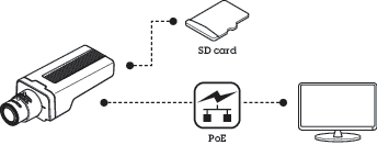
SD card slot
CAUTION
Moving parts. Risk of injury. Keep your body parts away from the product when it’s in operation. Disconnect from power supply before installing or performing maintenance on the product.
CAUTION
Hot surface. Risk of injury. Don’t touch the product when it’s in operation. Disconnect from power supply and allow the surfaces to cool before performing maintenance on the product.
NOTICE
Risk of damage to SD card. Don’t use sharp tools, metal objects, or excessive force when inserting or removing the SD card. Use your fingers to insert and remove the card.
Risk of data loss and corrupted recordings. Unmount the SD card from the device’s web interface before removing it. Don’t remove the SD card while the product is running.
This device supports SD/SDHC/SDXC cards.
This device supports microSD/microSDHC/microSDXC cards.
This device supports microSD/microSDHC/microSDXC cards (not included). For information about limitations and updates, see the device’s release notes.
SD, SDHC, and SDXC Logos are trademarks of SD-3C LLC. SD, SDHC and SDXC are trademarks or registered trademarks of SD-3C, LLC in the United States, other countries or both.
microSD, microSDHC, and microSDXC Logos are trademarks of SD-3C LLC. microSD, microSDHC, microSDXC are trademarks or registered trademarks of SD-3C, LLC in the United States, other countries or both.
Buttons
Control button
The control button is used for:
Enabling the Focus Assistant. Press and very quickly release the Control button.
Calibrating the speaker test. Press and release the control button and a test tone is played.
Ensuring the camera is level. Press the button for not more than two seconds to start the leveling assistant and press again to stop. The status LED and buzzer signal (see ) assist leveling of the camera. The camera is level when the buzzer beeps continuously.
Ensuring the camera is level. Press the button for not more than two seconds to start the leveling assistant and press again to stop. The buzzer signal (see Buzzer signal for leveling assistant) assist leveling of the camera. The camera is level when the buzzer beeps continuously.
Resetting the product to factory default settings. See or
Connecting to an AXIS Video Hosting System service. To connect, press and hold the button for about 3 seconds until the status LED flashes green.
Connecting to a one-click cloud connection (O3C) service over the internet. To connect, press and hold the button for about 3 seconds until the status LED flashes green.
Connectors
Network connector
The Axis product is available in two variants with different network connectors:
RJ45 Ethernet connector.
RJ45 Ethernet connector with Power over Ethernet (PoE).
RJ45 Ethernet connector with Power over Ethernet Plus (PoE+).
RJ45 with High Power over Ethernet (High PoE).
RJ45 Push-pull Connector (IP66) with High Power over Ethernet (High PoE).
RJ45 Ethernet service port.
D-coded M12 connector with Power over Ethernet (PoE).
TX+
RX+
TX-
RX-
SFP connector.
Input: RJ45 Ethernet connector with Power over Ethernet (PoE).
Output: RJ45 Ethernet connector with Power over Ethernet (PoE).
NOTICE
Use the supplied midspan.
NOTICE
Due to local regulations or the environmental and electrical conditions in which the product is to be used, a shielded network cable (STP) may be appropriate or required. All cables connecting the product to the network and that are routed outdoors or in demanding electrical environments shall be intended for their specific use. Make sure that the network devices are installed in accordance with the manufacturer’s instructions. For information about regulatory requirements, see .
NOTICE
The product shall be connected using a shielded network cable (STP). All cables connecting the product to the network shall be intended for their specific use. Make sure that the network devices are installed in accordance with the manufacturer’s instructions. For information about regulatory requirements, see .
NOTICE
The product shall be connected using a shielded network cable (STP) or an optical fiber cable. All cables connecting the product to the network shall be intended for their specific use. Make sure that the network devices are installed in accordance with the manufacturer’s instructions. For information about regulatory requirements, see .
NOTICE
To comply with the IP66-rated design of the camera and maintain the IP66 protection, the supplied RJ45 Push-pull Connector (IP66) shall be used. Alternatively, use the RJ45 IP66-rated cable with premounted connector which is available from your Axis reseller. Do not remove the plastic network connector shield from the camera.
NOTICE
The product shall be connected using a shielded network cable (STP). All cables connecting the product to the network shall be intended for their specific use. Make sure that the network devices are installed in accordance with the manufacturer’s instructions. For information about regulatory requirements, see the Installation Guide at www.axis.com.
Audio connector
3.5 mm connector
Audio in – 3.5 mm input for a mono microphone, or a line-in mono signal (left channel is used from a stereo signal).
Audio in – 3.5 mm input for a digital microphone, an analog mono microphone, or a line-in mono signal (left channel is used from a stereo signal).
Audio in – 3.5 mm input for two mono microphones, or two line-in mono signals (using the supplied stereo-to-mono adapter).
Audio in – 3.5 mm input for a stereo microphone, or a line-in stereo signal.
Audio out – 3.5 mm output for audio (line level) that can be connected to a public address (PA) system or an active speaker with a built-in amplifier. A stereo connector must be used for audio out.
Audio out – 3.5 mm output for audio (line level) that can be connected to a public address (PA) system or an active speaker with balanced input and a built-in amplifier. A balanced connector must be used for audio out.
Audio out – 3.5 mm output for audio (line level) that can be connected to a public address (PA) system or an active speaker with a built-in amplifier. A pair of headphones can also be attached. A stereo connector must be used for audio out.
Audio input
1 Tip
2 Ring
3 Sleeve
Unbalanced microphone (with or without electret power) or line
Electret power if selected
Ground
Balanced microphone (with or without phantom power) or line, “hot” signal
Balanced microphone (with or without phantom power) or line, “cold” signal
Ground
Digital signal
Ring power if selected
Ground
Stereo unbalanced microphone (with or without electret power) or line, “left”
Stereo unbalanced microphone (with or without electret power) or line, “right”
Ground
Audio output
1 Tip
2 Ring
3 Sleeve
Channel 1, unbalanced line, mono
Channel 1, unbalanced line, mono
Ground
Balanced line, “hot” signal
Balanced line, “cold” signal
Ground
Stereo unbalanced line, “left”
Stereo unbalanced line, “right”
Ground
Channel 1, unbalanced line
Channel 2, unbalanced line
Ground
4-pin terminal block for audio input and output.
Function
Pin
Notes
GND
1
Ground
Ring power
2
12 V for external source
Microphone/Line in
3
Microphone (analog or digital) or line in (mono). 5 V microphone bias is available.
Line out
4
Line level audio output (mono). Can be connected to a public address (PA) system or an active speaker with a built-in amplifier.
2-pin terminal block for line out.
Function
Pin
Notes
Line out (+)
1
Line audio out
0 V DC (-)
2
The internal microphone is used by default; the external microphone is used when connected. You can disable the internal microphone by connecting a plug to the microphone input.
The external microphone is used when connected.
XLR connector
Left – 3-pin XLR connector for balanced audio input. Use left connector for mono.
Right – 3-pin XLR connector for balanced audio input.
Pin
1
2
3
Function
Ground
Balanced Microphone Hot (+) In
Balanced Microphone Cold (-) In
I/O connector
Use the I/O connector with external devices in combination with, for example, motion detection, event triggering, and alarm notifications. In addition to the 0 V DC reference point and power (12 V DC output), the I/O connector provides the interface to:
Use the I/O connector with external devices in combination with, for example, event triggering and alarm notifications. In addition to the 0 V DC reference point and power (DC output), the I/O connector provides the interface to:
Digital input
For connecting devices that can toggle between an open and closed circuit, for example PIR sensors, door/window contacts, and glass break detectors.
Supervised input
Enables possibility to detect tampering on a digital input.
Digital output
For connecting external devices such as relays and LEDs. Connected devices can be activated by the VAPIX® Application Programming Interface, through an event or from the device’s web interface.
A digital light sensor
For receiving a value of the ambient light intensity from an external light sensor. This is used to control the device’s day and night functionality.
Note
The I/O connector is connected to the housing (fan/heater) on delivery. In case of a fan or heater error, an input signal will be triggered in the camera. Set up an action rule in the camera to configure which action the signal shall trigger.
The I/O connector is connected to the housing (fan/heater) on delivery. In case of a fan or heater error, an input signal will be triggered in the camera. Set up an action rule in the camera to configure which action the signal shall trigger. For information about events and action rules, see the user manual available on axis.com.
4-pin terminal block
6-pin terminal block
Example
DC ground
DC output 12 V, max 25 mA
Digital input
Digital output
DC ground
DC output 12 V, max 50mA
I/O configured as input
I/O configured as output
DC ground
DC output 12 V, max 50 mA
I/O configured as input
I/O configured as output
Configurable I/O
Configurable I/O
Power connector
Terminal connector for connecting AC/DC power supply.
DC connector. Use the supplied adapter.
This microUSB type B connector is for power only. We recommend using Axis microUSB power supply.
AC/DC connector. Use the supplied adapter.
2-pin terminal block for DC power input. Use a Safety Extra Low Voltage (SELV) compliant limited power source (LPS) with either a rated output power limited to ≤100 W or a rated output current limited to ≤5 A.
2-pin terminal block for AC/DC power input. Use a Safety Extra Low Voltage (SELV) compliant limited power source (LPS) with either a rated output power limited to ≤100 W or a rated output current limited to ≤5 A.
3-pin terminal block for power input. Use a Safety Extra Low Voltage (SELV) compliant limited power source (LPS) with either a rated output power limited to ≤100 W or a rated output current limited to ≤5 A.
DC power input:
AC power input:
AC connector for power input. Use the supplied cable.
2-pin terminal block for DC power output.
4-pin terminal block for power input.
DC power input:
5–pin DC connector
Pin
Function
1, 2
+24 V
3, 4
GND
5
N.C.
RS485/RS422 connector
Two 2-pin terminal blocks for RS485/RS422 serial interface used to control auxiliary equipment such as pan-tilt devices.
The serial port can be configured to support:
Two-wire RS485 half duplex
Four-wire RS485 full duplex
Two-wire RS422 simplex
Four-wire RS422 full duplex point to point communication
Function
Pin
Notes
RS485B alt RS485/422 RX(B)
1
RX pair for all modes (combined RX/TX for 2-wire RS485)
RS485A alt RS485/422 RX(A)
2
RS485/RS422 TX(B)
3
TX pair for RS422 and 4-wire RS485
RS485/RS422 TX(A)
4
Important
The maximum cable length is 30 m (98 ft).
Operating conditions
The Axis product is intended for indoor use.
Product
Temperature
Humidity
AXIS P1367
0°C to 50°C(32°F to 122°F)
10–85%RH (non-condensing)
Power consumption
NOTICE
Use a limited power source (LPS) with either a rated output power limited to ≤100W or a rated output current limited to ≤5A.
Product
Power over Ethernet (PoE) IEEE 802.3af/802.3at Type 1 Class 3