Preview mode is ideal for installers when fine tuning the camera view during the installation. No login is required to access the camera view in preview mode. It is available only in factory defaulted state for a limited time from powering up the device.
This video demonstrates how to use preview mode.
Get started
Find the device on the network
To find Axis devices on the network and assign them IP addresses in Windows®, use AXIS IP Utility or AXIS Device Manager. Both applications are free and can be downloaded from axis.com/support.
You can use the device with the following browsers:
ChromeTM
EdgeTM
Firefox®
Safari®
Windows®
✓
✓
*
*
macOS®
✓
✓
*
*
Linux®
✓
✓
*
*
Other operating systems
*
*
*
*
✓: Recommended *: Supported with limitations
Open the device's web interface
Open a browser and type the IP address or host name of the Axis device.
If you don’t know the IP address, use AXIS IP Utility or AXIS Device Manager to find the device on the network.
Type the username and password. If you access the device for the first time, you must create an administrator account. See Create an administrator account.
For descriptions of all features and settings in the web interface of devices with AXIS OS, see AXIS OS web interface help.
Create an administrator account
The first time you log in to your device, you must create an administrator account.
The device has no default account. If you lose the password for your administrator account, you must reset the device. See Reset to factory default settings.
Secure passwords
Important
Use HTTPS (which is enabled by default) to set your password or other sensitive configurations over the network. HTTPS enables secure and encrypted network connections, thereby protecting sensitive data, such as passwords.
The device password is the primary protection for your data and services. Axis devices do not impose a password policy as they may be used in various types of installations.
To protect your data we strongly recommend that you:
Use a password with at least 8 characters, preferably created by a password generator.
Don’t expose the password.
Change the password at a recurring interval, at least once a year.
Web interface overview
This video gives you an overview of the device’s web interface.
Stop all recordings and disconnect power from the device.
Disconnect the lens cable and remove the standard lens.
Attach the new lens and connect the lens cable.
Reconnect the power.
Log in to the device’s web interface and go to Video > Image > Exposure.
Select the P-Iris lens you have installed.
Note
If you use a DC iris, manual iris or optional i-CS lens there is no need to select a lens driver.
For the changes to take effect, you need to restart the device. Go to Maintenance and click Restart.
Adjust the zoom and focus.
Note
For a lens with P-Iris, DC-iris, or manual iris, manually adjust the focus on the lens before you fine-tune the focus through the web interface.
Adjust the image
This section includes instructions about configuring your device. If you want to learn more about how certain features work, go to Learn more.
Level the camera
To adjust the view in relation to a reference area or an object, use the level grid in combination with a mechanical adjustment of the camera.
Go to Video > Image > and click .
Click to show the level grid.
Adjust the camera mechanically until the position of the reference area or the object is aligned with the level grid.
Adjust the zoom and focus
To adjust the zoom:
Go to Video > Installation and adjust the zoom slider.
To adjust the focus:
Click to show the autofocus area.
Adjust the autofocus area to cover the part of the image that you want to be in focus.
If you don’t select an autofocus area, the camera focuses on the entire scene. We recommend that you focus on a static object.
Click Autofocus.
To fine tune the focus, adjust the focus slider.
Select scene profile
A scene profile is a set of predefined image appearance settings including color level, brightness, sharpness, contrast and local contrast. Scene profiles are preconfigured in the product for quick setup to a specific scenario, for example Forensic which is optimized for surveillance conditions. For a description of each available setting, see The web interface.
You can select a scene profile during the initial setup of the camera. You can also select or change scene profile later.
Go to Video > Image > Appearance.
Go to Scene profile and select a profile.
Select exposure mode
To improve image quality for specific surveillance scenes, use exposure modes. Exposure modes lets you control aperture, shutter speed, and gain. Go to Video > Image > Exposure and select between the following exposure modes:
For most use cases, select Automatic exposure.
For environments with certain artificial lighting, for example fluorescent lighting, select Flicker-free.
Select the same frequency as the power line frequency.
For environments with certain artificial light and bright light, for example outdoors with fluorescent lighting at night and sun during daytime, select Flicker-reduced.
Select the same frequency as the power line frequency.
To lock the current exposure settings, select Hold current.
Benefit from IR light in low-light conditions by using night mode
Your camera uses visible light to deliver color images during the day. But as the visible light diminishes, color images become less bright and clear. If you switch to night mode when this happens, the camera uses both visible and near-infrared light to deliver bright and detailed black-and-white images instead. You can set the camera to switch to night mode automatically.
Go to Video > Image > Day-night mode, and make sure that the IR-cut filter is set to Auto.
Reduce noise in low-light conditions
To reduce noise in low-light conditions, you can adjust one or more of the following settings:
Adjust the trade-off between noise and motion blur. Go to Video > Image > Exposure and move the Blur-noise trade-off slider toward Low noise.
Set the exposure mode to automatic.
Note
A high max shutter value can result in motion blur.
To slow down the shutter speed, set max shutter to the highest possible value.
Note
When you reduce the max gain, the image can become darker.
Set the max gain to a lower value.
If there is an Aperture slider, move it towards Open.
Reduce sharpness in the image, under Video > Image > Appearance.
Reduce motion blur in low-light conditions
To reduce motion blur in low-light conditions, adjust one or more of the following settings in Video > Image > Exposure:
Note
When you increase the gain, image noise also increases.
Set Max shutter to a shorter time, and Max gain to a higher value.
If you still have problems with motion blur:
Increase the light level in the scene.
Mount the camera so that objects move toward it or away from it rather than sideways.
Maximize the details in an image
Important
If you maximize the details in an image, the bitrate will probably increase and you might get a reduced frame rate.
Make sure to select the capture mode that has the highest resolution.
Go to Video > Stream > General and set the compression as low as possible.
Below the live view image, click and in Video format, select MJPEG.
Go to Video > Stream > Zipstream and select Off.
Handle scenes with strong backlight
Dynamic range is the difference in light levels in an image. In some cases the difference between the darkest and the brightest areas can be significant. The result is often an image where either the dark or the bright areas are visible. Wide dynamic range (WDR) makes both dark and bright areas of the image visible.
Image without WDR.Image with WDR.
Note
WDR can cause artifacts in the image.
WDR may not be available for all capture modes.
Go to Video > Image > Wide dynamic range.
Turn on WDR.
Use the Local contrast slider to adjust the amount of WDR.
If you still have problems, go to Exposure and adjust the Exposure zone to cover the area of interest.
Image stabilization is suitable in environments where the product is mounted in an exposed location where vibrations can occur, for example, due to wind or passing traffic.
The feature makes the image smoother, steadier, and less blurry. It also reduces the file size of the compressed image and lowers the bitrate of the video stream.
Note
When you turn on image stabilization, the image is slightly cropped, which lowers the maximum resolution.
Go to Video > Installation > Image correction.
Turn on Image stabilization.
Compensate for barrel distortion
Barrel distortion is a phenomenon where straight lines appear increasingly bent closer to the edges of the frame. A wide field of view often creates barrel distortion in an image. Barrel distortion correction compensates for this distortion.
Note
Barrel distortion correction affects the image resolution and field of view.
Go to Video > Installation > Image correction.
Turn on Barrel distortion correction (BDC).
Monitor long and narrow areas
Use corridor format to better utilize the full field of view in a long and narrow area, for example a staircase, hallway, road, or tunnel.
Depending on your device, turn the camera or the 3-axis lens in the camera 90° or 270°.
If the device doesn’t have automatic rotation of the view, go to Video > Installation.
Rotate the view 90° or 270°.
Verify the pixel resolution
To verify that a defined part of the image contains enough pixels to, for example, recognize the face of a person, you can use the pixel counter.
Go to Video > Image and click .
Click for Pixel counter.
In the camera’s live view, adjust the size and position of the rectangle around the area of interest, for example where you expect faces to appear.
You can see the number of pixels for each of the rectangle’s sides, and decide if the values are enough for your needs.
Hide parts of the image with privacy masks
You can create one or several privacy masks to hide parts of the image.
Go to Video > Privacy masks.
Click .
Click the new mask and type a name.
Adjust the size and placement of the privacy mask according to your needs.
To change the color for all privacy masks, click Privacy masks and select a color.
You can add an image as an overlay in the video stream.
Go to Video > Overlays.
Click Manage images.
Upload or drag and drop an image.
Click Upload.
Select Image from the drop-down list and click .
Select the image and a position. You can also drag the overlay image in the live view to change the position.
Show a text overlay
You can add a text field as an overlay in the video stream. This is useful for example when you want to display the date, time or a company name in the video stream.
Go to Video > Overlays.
Select Text and click .
Type the text you want to display, or select modifiers to show for example the current date.
Select a position. You can also click-and-drag the overlay in the live view to change the position.
Add street names and compass direction to the image
Note
The street name and compass direction will be visible on all video streams and recordings.
Go to Apps.
Select axis-orientationaid.
Click Open.
To add a street name, click Add text and modify the text to fit the street.
To add a compass, click Add compass and modify the compass to fit the image.
Adjust the camera view (PTZ)
Go to PTZ > Limits.
Set the limits as needed.
Create a guard tour with preset positions
A guard tour displays the video stream from different preset positions either in a predetermined or random order, and for configurable periods of time.
Go to PTZ > Guard tours.
Click Guard tour.
Select Preset position and click Create.
Under General settings:
Enter a name for the guard tour and specify the pause length between each tour.
If you want the guard tour to go to the preset positions in a random order, turn on Play guard tour in random order.
Under Step settings:
Set the duration for the preset.
Set the move speed, which controls how fast to move to the next preset.
Go to Preset positions.
Select the preset positions that you want in your guard tour.
Drag them to the View order area, and click Done.
To schedule the guard tour, go to System > Events.
View and record video
This section includes instructions about configuring your device. To learn more about how streaming and storage works, go to Streaming and storage.
Reduce bandwidth and storage
Important
Reducing the bandwidth can lead to loss of detail in the image.
Go to Video > Stream.
Click in the live view.
Select Video format AV1 if your device supports it. Otherwise select H.264.
Go to Video > Stream > General and increase Compression.
Go to Video > Stream > Zipstream and do one or more of the following:
Select the Zipstream Strength that you want to use.
Turn on Optimize for storage. This can only be used if the video management software supports B-frames.
Turn on Dynamic FPS.
Turn on Dynamic GOP and set a high Upper limit GOP length value.
Set up network storage
To store recordings on the network, you need to set up your network storage.
Go to System > Storage.
Click Add network storage under Network storage.
Type the IP address of the host server.
Type the name of the shared location on the host server under Network share.
Type the username and password.
Select the SMB version or leave it on Auto.
Select Add share without testing if you experience temporary connection issues, or if the share is not yet configured.
Click Add.
Record and watch video
Record video directly from the camera
Go to Video > Stream.
To start a recording, click .
If you haven’t set up any storage, click and . For instructions on how to set up network storage, see Set up network storage
To stop recording, click again.
Watch video
Go to Recordings.
Click for your recording in the list.
Set up rules for events
You can create rules to make your device perform an action when certain events occur. A rule consists of conditions and actions. The conditions can be used to trigger the actions. For example, the device can start a recording or send an email when it detects motion, or show an overlay text while the device is recording.
Go to System > Events and add a rule. The rule defines when the device will perform certain actions. You can set up rules as scheduled, recurring, or manually triggered.
Enter a Name.
Select the Condition that must be met to trigger the action. If you specify more than one condition for the rule, all of the conditions must be met to trigger the action.
Select which Action to perform when the conditions are met.
Note
If you make changes to an active rule, the rule must be turned on again for the changes to take effect.
Record video when the camera detects an object
This example explains how to set up the camera to start recording to the SD card when the camera detects an object. The recording will include five seconds before detection and one minute after detection ends.
Before you start:
Make sure you have an SD card installed.
Start the application if it is not already running.
Make sure you have set up the application according to your needs.
Create a rule:
Go to System > Events and add a rule.
Type a name for the rule.
In the list of actions, under Recordings, select Record video while the rule is active.
In the list of storage options, select SD_DISK.
Select a camera and a stream profile.
Set the prebuffer time to 5 seconds.
Set the postbuffer time to 1 minute.
Click Save.
Show a text overlay in the video stream when the device detects an object
This example explains how to display the text “Motion detected” when the device detects an object.
Start the application if it is not already running.
Make sure you have set up the application according to your needs.
Add the overlay text:
Go to Video > Overlays.
Under Overlays, select Text and click .
Enter #D in the text field.
Choose text size and appearance.
To position the text overlay, click and select an option.
Create a rule:
Go to System > Events and add a rule.
Type a name for the rule.
In the list of actions, under Overlay text, select Use overlay text.
Select a video channel.
In Text, type “Motion detected”.
Set the duration.
Click Save.
Record video when the camera detects loud noises
This example explains how to set up the camera to start recording to the SD card five seconds before it detects loud noise and to stop two minutes after.
Note
The following instructions require that a microphone is connected to audio-in.
In the list of conditions, under Audio, select Audio Detection.
In the list of actions, under Recordings, select Record video.
In the list of storage options, select SD_DISK.
Select the stream profile where audio has been turned on.
Set the prebuffer time to 5 seconds.
Set the postbuffer time to 2 minutes.
Click Save.
Record video when the camera detects impact
Shock detection allows the camera to detect tampering caused by vibrations or shock. Vibrations due to the environment or to an object can trigger an action depending on the shock sensitivity range, which can be set from 0 to 100. In this scenario, someone is throwing rocks at the camera after hours and you would like to get a video clip of the event.
Turn on shock detection:
Go to System > Detectors > Shock detection.
Turn on shock detection, and adjust the shock sensitivity.
Create a rule:
Go to System > Events > Rules and add a rule.
Type a name for the rule.
In the list of conditions, under Device status, select Shock detected.
Click + to add a second condition.
In the list of conditions, under Scheduled and recurring, select Schedule.
In the list of schedules, select After hours .
In the list of actions, under Recordings, select Record video while the rule is active.
Select where to save the recordings.
Select a Camera.
Set the prebuffer time to 5 seconds.
Set the postbuffer time to 50 seconds.
Click Save.
Trigger a notification when the camera lens is tampered
This example explains how to set up an email notification when the camera lens gets either spray painted, covered, or blurred.
Activate the tampering detection:
Go to System > Detectors > Camera tampering.
Set a value for Trigger delay. The value indicates the time that must pass before an email is sent.
Turn on Trigger on dark images to detect if the lens is sprayed, covered, or rendered severely out of focus.
Add an email recipient:
Go to System > Events > Recipients and add a recipient.
Type a name for the recipient.
Select Email as the notification type.
Type the recipient’s email address.
Type the email address that you want the camera to send notifications from.
Provide the login details for the sending email account, along with the SMTP hostname and port number.
To test your email setup, click Test.
Click Save.
Create a rule:
Go to System > Events > Rules and add a rule.
Type a name for the rule.
In the list of conditions, under Video, select Tampering.
In the list of actions, under Notifications, select Send notification to email and then select the recipient from the list.
Type a subject line and message for the email.
Click Save.
Audio
Add audio to your recording
Turn on audio:
Go to Video > Stream > Audio and include audio.
If the device has more than one input source, select the correct one in Source.
Go to Audio > Device settings and turn on the correct input source.
If you make any changes to the input source, click Apply changes.
Edit the stream profile that is used for the recording:
Go to System > Stream profiles and select the stream profile.
Select Include audio and turn it on.
Click Save.
The web interface
To read about all the features and settings available in the web interface of devices with AXIS OS, go to AXIS OS web interface help.
Learn more
Choose lens
There is more than one lens option for your camera. Which lens to choose depends on the surveillance requirements. The lenses have different capabilities when it comes to light sensitivity and field of view. See the product’s datasheet for lens alternatives.
Depth of field and sensor size
The depth of field depends on the lens aperture, the size of the image sensor and the distance to the scene. The lower the f-number and larger the sensor, the shallower depth of field. Due to the large sensor, the depth of field is more shallow in this particular product than in traditional surveillance cameras. Depth of field becomes shallower in dark conditions, due to the fact that the iris opens up to provide enough light to the sensor.
The focus point is affected by the aperture (f-stop) of the lens. The lower the f-stop value, the more light reaches the image sensor. The smaller the aperture, the deeper depth of field which may lead to an unwanted absolute focus point. During low light conditions, when the aperture is as large as possible, the depth of field decreases and the image may therefore appear unfocused.
Examples of apertures for different f-numbers.
To calculate the distance between the camera and the object of interest in relation to scene dimensions, resolution, and focal length, use the lens calculator tool, go to axis.com/tools/lens-calculator.
Long-distance connections
This product supports fiber-optic cable installations through a media converter. Fiber-optic cable installations offer a number of benefits such as:
Long-distance connection
High speed
Long lifetime
Large capacity of data transmission
Electromagnetic interference immunity
Find out more about fiber-optic cable installations in the white paper “Long distance surveillance - Fiber-optic communication in network video” at axis.com/learning/white-papers.
For information about how to install the media converter see the Installation Guide for this product.
View area
A view area is a cropped part of the full view. You can stream and store view areas instead of the full view to minimize bandwidth and storage needs. If you enable PTZ for a view area, you can pan, tilt and zoom within it. By using view areas you can remove parts of the full view, for example, the sky.
When you set up a view area, we recommend you to set the video stream resolution to the same size as or smaller than the view area size. If you set the video stream resolution larger than the view area size it implies digitally scaled up video after sensor capture, which requires more bandwidth without adding image information.
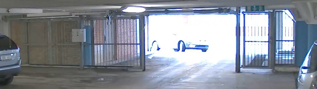
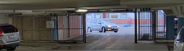
Capture modes
A capture mode is a preset configuration that defines how the camera captures images. The capture mode setting can affect the camera’s field of view and aspect ratio. The shutter speed can also be affected, which in turn affects the light sensitivity.
The lower resolution capture mode might be sampled from the original resolution, or it might be cropped out from the original, in which case the field of view could also be affected.
The image shows how the field of view and aspect ratio can change between two different capture modes.
What capture mode to choose depends on the requirements for the frame rate and resolution of the specific surveillance setup. For specifications about available capture modes, see the product’s datasheet at axis.com.
Remote focus and zoom
The remote focus and zoom functionality allows you to make focus and zoom adjustments to your camera from a computer. It is a convenient way to ensure that the scene’s focus, viewing angle and resolution are optimized without having to visit the camera’s installation location.
Privacy masks
A privacy mask is a user-defined area that prevents users from viewing a part of the monitored area. In the video stream, privacy masks appear as blocks of solid color.
You’ll see the privacy mask on all snapshots, recorded video, and live streams.
You can use the VAPIX® application programming interface (API) to hide the privacy masks.
Important
If you use multiple privacy masks it may affect the product’s performance.
You can create several privacy masks. Each mask can have 3 to 10 anchor points.
Important
Set the zoom and focus before you create a privacy mask.
Overlays
Overlays are superimposed over the video stream. They are used to provide extra information during recordings, such as a timestamp, or during product installation and configuration. You can add either text or an image.
Streaming and storage
Video compression formats
Decide which compression method to use based on your viewing requirements, and on the properties of your network. The available options are:
Motion JPEG
Motion JPEG, or MJPEG, is a digital video sequence that is made up of a series of individual JPEG images. These images are then displayed and updated at a rate sufficient to create a stream that shows constantly updated motion. For the viewer to perceive motion video the rate must be at least 16 image frames per second. Full motion video is perceived at 30 (NTSC) or 25 (PAL) frames per second.
The Motion JPEG stream uses considerable amounts of bandwidth, but provides excellent image quality and access to every image contained in the stream.
H.264 or MPEG-4 Part 10/AVC
Note
H.264 is a licensed technology. The Axis product includes one H.264 viewing client license. To install additional unlicensed copies of the client is prohibited. To purchase additional licenses, contact your Axis reseller.
H.264 can, without compromising image quality, reduce the size of a digital video file by more than 80% compared to the Motion JPEG format and by as much as 50% compared to older MPEG formats. This means that less network bandwidth and storage space are required for a video file. Or seen another way, higher video quality can be achieved for a given bitrate.
How do Image, Stream, and Stream profile settings relate to each other?
The Image tab contains camera settings that affect all video streams from the product. If you change something in this tab, it immediately affects all video streams and recordings.
The Stream tab contains settings for video streams. You get these settings if you request a video stream from the product and don’t specify for example resolution, or frame rate. When you change the settings in the Stream tab, it doesn’t affect ongoing streams, but it will take effect when you start a new stream.
The Stream profiles settings override the settings from the Stream tab. If you request a stream with a specific stream profile, the stream contains the settings of that profile. If you request a stream without specifying a stream profile, or request a stream profile that doesn't exist in the product, the stream contains the settings from the Stream tab.
Bitrate control
Bitrate control helps you to manage the bandwidth consumption of your video stream.
Variable bitrate (VBR) Variable bitrate allows the bandwidth consumption to vary depending on the level of activity in the scene. The more activity, the more bandwidth you need. With variable bitrate you are guaranteed constant image quality, but you need to make sure you have storage margins.
Maximum bitrate (MBR) Maximum bitrate lets you set a target bitrate to handle bitrate limitations in your system. You might see a decline in image quality or frame rate as the instantaneous bitrate is kept below the specified target bitrate. You can choose to prioritize either image quality or frame rate. We recommend that you configure the target bitrate to a higher value than the expected bitrate. This gives you a margin in case there is a high level of activity in the scene.
Target bitrate
Average bitrate (ABR) With average bitrate, the bitrate is automatically adjusted over a longer period of time. This is so you can meet the specified target and provide the best video quality based on your available storage. Bitrate is higher in scenes with a lot of activity, compared to static scenes. You are more likely to get better image quality when in scenes with a lot of activity if you use the average bitrate option. You can define the total storage required to store the video stream for a specified amount of time (retention time) when image quality is adjusted to meet the specified target bitrate. Specify the average bitrate settings in one of the following ways:
To calculate the estimated storage need, set the target bitrate and the retention time.
To calculate the average bitrate, based on available storage and required retention time, use the target bitrate calculator.
Target bitrate
Actual average bitrate
You can also turn on maximum bitrate and specify a target bitrate within the average bitrate option.
Target bitrate
Actual average bitrate
Analytics and apps
With analytics and apps you can get more out of your Axis device. AXIS Camera Application Platform (ACAP) is an open platform that makes it possible for third parties to develop analytics and other apps for Axis devices. Apps can be preinstalled on the device, available for download for free, or for a license fee.
To find the user manuals for Axis analytics and apps, go to help.axis.com.
Note
We recommended running one app at a time.
Avoid running apps when the built-in motion detection is active.
Cybersecurity
For product-specific information about cybersecurity, see the product's datasheet at axis.com.
Signed OS is implemented by the software vendor signing the AXIS OS image with a private key. When the signature is attached to the operating system, the device will validate the software before installing it. If the device detects that the integrity of the software is compromised, the AXIS OS upgrade will be rejected.
To learn more about the cybersecurity features in Axis devices, go to axis.com/learning/white-papers and search for cybersecurity.
Specifications
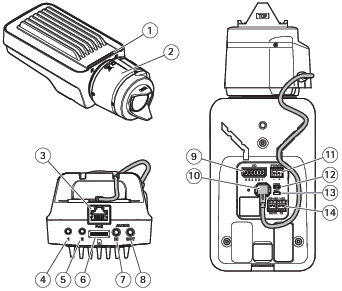
Product overview
Status LED indicator
Lens
Network connector (PoE)
Control button (1)
Function button (2)
microSD Card slot
Audio in
Audio out
I/O connector
Iris connector
Power connector
Power LED indicator
Network LED indicator
RS485/RS422 connector
LED Indicators
Note
The Status LED can be configured to be unlit during normal operation. To configure, go to Settings > System > Plain config.
The Status LED can be configured to flash while an event is active.
Status LED
Indication
Green
Steady green for normal operation.
Amber
Steady during startup. Flashes when restoring settings.
Note
The Network LED can be disabled so that it does not flash when there is network traffic. To configure, go to Settings > System > Plain config.
Network LED
Indication
Green
Steady for connection to a 100 Mbit/s network. Flashes for network activity.
Amber
Steady for connection to a 10 Mbit/s network. Flashes for network activity.
Unlit
No network connection.
Note
The Power LED can be configured to be unlit during normal operation. To configure, go to Settings > System > Plain config.
Power LED
Indication
Green
Normal operation.
Amber
Flashes green/amber during firmware upgrade.
Status LED behavior for focus assistant
Note
Only valid for optional P-iris, DC-iris or manual iris lenses.
The status LED flashes when the Focus Assistant is active.
Color
Indication
Red
The image is out of focus. Adjust the lens.
Amber
The image is close to focus. The lens needs fine tuning.
Green
The image is in focus.
Buzzer signal for focus assistant
Note
Only valid for optional P-iris, DC-iris or manual iris lenses.
Buzzer
Lens
Fast interval
Optimally adjusted
Medium interval
Less optimally adjusted
Slow interval
Poorly adjusted
Status LED behavior and buzzer signal for leveling assistant
For information on the function button used for leveling the camera, see Buttons.
Color
Buzzer
Camera position
Fixed green
Continuous beep
Level
Flashing green
Fast beeps
Almost level
Flashing orange
Medium beeps
Not level
Flashing red
Slow beeps
Far from level
SD card slot
NOTICE
Risk of damage to SD card. Don’t use sharp tools, metal objects, or excessive force when inserting or removing the SD card. Use your fingers to insert and remove the card.
Risk of data loss and corrupted recordings. Unmount the SD card from the device’s web interface before removing it. Don’t remove the SD card while the product is running.
This device supports microSD/microSDHC/microSDXC cards.
microSD, microSDHC, and microSDXC Logos are trademarks of SD-3C LLC. microSD, microSDHC, microSDXC are trademarks or registered trademarks of SD-3C, LLC in the United States, other countries or both.
Focus assistant is only valid for optional P-iris, DC-iris or manual iris lenses.
Use the function button to activate the following functions:
Leveling assistant
This function helps to make sure the camera is level. To start the leveling assistant, press the button for about 3 seconds. Press again to stop the leveling assistant. The status LED and buzzer signal assist leveling of the camera, see . The camera is level when the buzzer beeps continuously.
Focus assistant
This function is used for enabling the focus assistant. To enable the focus assistant, press and very quickly release the button. Press again to stop the focus assistant. To find out more, see the Installation Guide.
Connectors
Network connector
RJ45 Ethernet connector with Power over Ethernet (PoE).
Audio connector
Audio in – 3.5 mm input for a mono microphone, or a line-in mono signal (left channel is used from a stereo signal).
Audio out – 3.5 mm output for audio (line level) that can be connected to a public address (PA) system or an active speaker with a built-in amplifier. A stereo connector must be used for audio out.
Audio input
1 Tip
2 Ring
3 Sleeve
Balanced microphone (with or without phantom power) or line-in, “hot” signal
Balanced microphone (with or without phantom power) or line-in, “cold” signal
Ground
Audio output
1 Tip
2 Ring
3 Sleeve
Channel 1, unbalanced line, mono
Channel 1, unbalanced line, mono
Ground
The internal microphone is used by default; the external microphone is used when connected. You can disable the internal microphone by connecting a plug to the microphone input.
I/O connector
Use the I/O connector with external devices in combination with, for example, motion detection, event triggering, and alarm notifications. In addition to the 0 VDC reference point and power (12 V DC output), the I/O connector provides the interface to:
Digital input
For connecting devices that can toggle between an open and closed circuit, for example PIR sensors, door/window contacts, and glass break detectors.
Digital output
For connecting external devices such as relays and LEDs. Connected devices can be activated by the VAPIX® Application Programming Interface, through an event or from the device’s web interface.
6-pin terminal block
Function
Pin
Notes
Specifications
DC ground
1
0 VDC
DC output
2
Can be used to power auxiliary equipment. Note: This pin can only be used as power out.
12 VDC Max load = 50 mA
Configurable (Input or Output)
3–6
Digital input – Connect to pin 1 to activate, or leave floating (unconnected) to deactivate.
0 to max 30 VDC
Digital output – Internally connected to pin 1 (DC ground) when active, and floating (unconnected) when inactive. If used with an inductive load, e.g., a relay, connect a diode in parallel with the load, to protect against voltage transients.
0 to max 30 VDC, open drain, 100 mA
Example
DC ground
DC output 12 V, max 50 mA
I/O configured as input
I/O configured as output
Configurable I/O
Configurable I/O
Power connector
2-pin terminal block for DC power input. Use a Safety Extra Low Voltage (SELV) compliant limited power source (LPS) with either a rated output power limited to ≤100 W or a rated output current limited to ≤5 A.
RS485/RS422 connector
Two 2-pin terminal blocks for RS485/RS422 serial interface.
The serial port can be configured to support:
Two-wire RS485 half duplex
Four-wire RS485 full duplex
Two-wire RS422 simplex
Four-wire RS422 full duplex point to point communication
Function
Notes
RS485/RS422 TX(A)
TX pair for RS422 and 4-wire RS485
RS485/RS422 TX(B)
RS485A alt RS485/422 RX(A)
RX pair for all modes (combined RX/TX for 2-wire RS485)
RS485B alt RS485/422 RX(B)
Troubleshooting
Reset to factory default settings
Important
Reset to factory default should be used with caution. A reset to factory default resets all settings, including the IP address, to the factory default values.
To reset the product to the factory default settings:
Disconnect power from the product.
Press and hold the control button while reconnecting power. See Product overview.
Keep the control button pressed for 15–30 seconds until the status LED indicator flashes amber.
Release the control button. The process is complete when the status LED indicator turns green. If no DHCP server is available on the network, the device IP address will default to one of the following:
Devices with AXIS OS 12.0 and later: Obtained from the link-local address subnet (169.254.0.0/16)
Devices with AXIS OS 11.11 and earlier: 192.168.0.90/24
Use the installation and management software tools to assign an IP address, set the password, and access the device.
The installation and management software tools are available from the support pages on axis.com/support.
You can also reset parameters to factory default through the device’s web interface. Go to Maintenance > Factory default and click Default.
Check the current AXIS OS version
AXIS OS determines the functionality of our devices. When you troubleshoot a problem, we recommend that you to start by checking the current AXIS OS version. The latest version might contain a correction that fixes your particular problem.
To check the current AXIS OS version:
Go to the device’s web interface > Status.
Under Device info, see the AXIS OS version.
Upgrade AXIS OS
Important
When you upgrade the device software, your preconfigured and customized settings are saved. Axis Communications AB can't guarantee that the settings are saved, even if the features are available in the new AXIS OS version.
Starting from AXIS OS 12.6, you must install every LTS version between your device’s current version and the target version. For example, if the currently installed device software version is AXIS OS 11.2, you have to install the LTS version AXIS OS 11.11 before you can upgrade the device to AXIS OS 12.6. For more information, see AXIS OS Portal: Upgrade path.
Make sure the device remains connected to the power source throughout the upgrade process.
Note
When you upgrade the device with the latest AXIS OS version in the active track, the product receives the latest functionality available. Always read the upgrade instructions and release notes available with each new release before you upgrade. To find the latest AXIS OS version and the release notes, go to axis.com/support/device-software.
If the upgrade fails, the device reloads the previous version. The most common reason is that the wrong AXIS OS file has been uploaded. Check that the name of the AXIS OS file corresponds to your device and try again.
Problems after AXIS OS upgrade
If you experience problems after the upgrade, roll back to the previously installed version from the Maintenance page.
Problems setting the IP address
Can’t set the IP address
If the IP address intended for the device and the IP address of the computer used to access the device are located on different subnets, you can’t set the IP address. Contact your network administrator to obtain an IP address.
The IP address could be in use by another device. To check:
Disconnect the Axis device from the network.
In a Command/DOS window, type ping and the IP address of the device.
If you receive: Reply from <IP address>: bytes=32; time=10... this means that the IP address might already be in use by another device on the network. Obtain a new IP address from the network administrator and reinstall the device.
If you receive: Request timed out, this means that the IP address is available for use with the Axis device. Check all cabling and reinstall the device.
There could be a possible IP address conflict with another device on the same subnet. The static IP address in the Axis device is used before the DHCP server sets a dynamic address. This means that if the same default static IP address is also used by another device, there could be problems accessing the device.
Problems accessing the device
Can’t log in when accessing the device from a browser
When HTTPS is enabled, make sure that you use the correct protocol (HTTP or HTTPS) when you try to log in. You might need to manually type http or https in the browser’s address field.
If you’ve lost the password for the root account, you must reset the device to the factory default settings. For instructions, see Reset to factory default settings.
The IP address has been changed by DHCP
IP addresses obtained from a DHCP server are dynamic and could change. If the IP address has been changed, use AXIS IP Utility or AXIS Device Manager to locate the device on the network. Identify the device using its model or serial number, or by the DNS name (if the name has been configured).
If required, you can assign a static IP address manually. For instructions, go to axis.com/support.
Certificate error when using IEEE 802.1X
For authentication to work properly, the date and time settings in the Axis device must be synchronized with an NTP server. Go to System > Date and time.
To access the device externally, we recommend you to use one of the following applications for Windows®:
AXIS Camera Station Edge: free of charge, ideal for small systems with basic surveillance needs.
AXIS Camera Station Pro: 90-day trial version free of charge, ideal for small to mid-size systems.
For instructions and download, go to axis.com/vms.
Problems with streaming
Multicast H.264 only accessible by local clients
Check if your router supports multicasting, or if you need to configure the router settings between the client and the device. You might need to increase the TTL (Time To Live) value.
No multicast H.264 displayed in the client
Check with your network administrator that the multicast addresses used by the Axis device are valid for your network.
Check with your network administrator to see if there is a firewall that prevents viewing.
Poor rendering of H.264 images
Ensure that your graphics card uses the latest driver. You can usually download the latest drivers from the manufacturer’s website.
Color saturation is different in H.264 and Motion JPEG
Modify the settings for your graphics adapter. Check the adapter’s documentation for more information.
Reduce the number of applications running on the client computer.
Limit the number of simultaneous viewers.
Check with the network administrator that there is enough bandwidth available.
Lower the image resolution.
Log in to the device’s web interface and set a capture mode that prioritizes frame rate. If you change the capture mode to prioritize frame rate it might lower the maximum resolution, depending on the device used and capture modes available.
The maximum frames per second is dependent on the utility frequency (60/50 Hz) of the Axis device.
Can't select H.265 encoding in live view
Web browsers don’t support H.265 decoding. Use a video management system or application that supports H.265 decoding.
Problems with MQTT
Can’t connect over port 8883 with MQTT over SSL
The firewall blocks traffic that uses port 8883 since it’s regarded insecure.
In some cases the server/broker might not provide a specific port for MQTT communication. It might still be possible to use MQTT over a port normally used for HTTP/HTTPS traffic.
If the server/broker supports WebSocket/WebSocket Secure (WS/WSS), typically on port 443, use this protocol instead. Check with the server/broker provider to see if WS/WSS is supported and which port and basepath to use.
If the server/broker supports ALPN, the use of MQTT can be negotiated over an open port, such as 443. Check with your server/broker provider to see if ALPN is supported and which ALPN protocol and port to use.
Problems with operating the device
Front heater and wiper aren’t working
If the front heater or wiper are not turning on, confirm that the top cover is properly fastened to the bottom of the housing unit.
If you can’t find what you’re looking for here, try the troubleshooting section at axis.com/support.
Performance considerations
When you set up your system, it’s important to consider how different settings and situations affect performance. Some factors affect bandwidth (bitrate), others affect frame rate, and some affect both.
The most important factors to consider:
High image resolution or lower compression levels result in images containing more data which in turn affects the bandwidth.
Rotating the image in the GUI can increase the product's CPU load.
Access by large numbers of Motion JPEG clients or unicast H.264/H.265/AV1 clients affects the bandwidth.
Simultaneous viewing of different streams (resolution, compression) by different clients affects both frame rate and bandwidth.
Use identical streams wherever possible to maintain a high frame rate. Stream profiles can be used to ensure that streams are identical.
Accessing video streams with different codecs simultaneously affects both frame rate and bandwidth. For optimal performance, use streams with the same codec.
Heavy usage of event settings affects the product’s CPU load which in turn affects the frame rate.
Using HTTPS may reduce frame rate, in particular if streaming Motion JPEG.
Heavy network utilization due to poor infrastructure affects the bandwidth.
Viewing on poorly performing client computers lowers perceived performance and affects frame rate.
Running multiple AXIS Camera Application Platform (ACAP) applications simultaneously may affect the frame rate and the general performance.