Solution overview
The network door controller can easily be connected to and powered by your existing IP network with no need for special cabling.
Each network door controller is an intelligent device that is easily mounted close to a door. It can power and control up to two readers.
Installation
Get started
Find the device on the network
To find Axis devices on the network and assign them IP addresses in Windows®, use AXIS IP Utility or AXIS Device Manager. Both applications are free and can be downloaded from axis.com/support.
For more information about how to find and assign IP addresses, go to How to assign an IP address and access your device.
Browser support
You can use the device with the following browsers:
ChromeTM | EdgeTM | Firefox® | Safari® | |
Windows® | ✓ | ✓ | * | * |
macOS® | ✓ | ✓ | * | * |
Linux® | ✓ | ✓ | * | * |
Other operating systems | * | * | * | * |
✓: Recommended
*: Supported with limitations
Open the device's web interface
Open a browser and type the IP address or host name of the Axis device.
If you don’t know the IP address, use AXIS IP Utility or AXIS Device Manager to find the device on the network.
Type the username and password. If you access the device for the first time, you must create an administrator account. See Create an administrator account.
For descriptions of all features and settings in the web interface of devices with AXIS OS, see AXIS OS web interface help.
Create an administrator account
The first time you log in to your device, you must create an administrator account.
Enter a username.
Enter a password. See Secure passwords.
Re-enter the password.
Accept the license agreement.
Click Add account.
The device has no default account. If you lose the password for your administrator account, you must reset the device. See Reset to factory default settings.
Secure passwords
Use HTTPS (which is enabled by default) to set your password or other sensitive configurations over the network. HTTPS enables secure and encrypted network connections, thereby protecting sensitive data, such as passwords.
The device password is the primary protection for your data and services. Axis devices do not impose a password policy as they may be used in various types of installations.
To protect your data we strongly recommend that you:
Use a password with at least 8 characters, preferably created by a password generator.
Don’t expose the password.
Change the password at a recurring interval, at least once a year.
Make sure that no one has tampered with the device software
- To make sure that the device has its original AXIS OS, or to take full control of the device after a security attack:
Reset to factory default settings. See Reset to factory default settings.
After the reset, secure boot guarantees the state of the device.
Configure and install the device.
Web interface overview
This video gives you an overview of the device’s web interface.
Configure your device
For how to configure your device, see AXIS Camera Station user manual or third-party solutions.
Door override
This feature takes direct control of the door relays and overrides the relay configuration in AXIS Camera Station. Only use it if Axis support has instructed you to do so.
Stop the Secure Entry service in AXIS Camera Station.
In the door controller's web interface, go to Advanced > Door override.
Read the information on the page carefully, then click I understand.
Turn on Door override and click Enable.
Go to the door relay, click Lock, Unlock, or Access to lock the door, unlock the door, or grant access.
Go to the relay you want to configure and click Activate or Deactivate to activate or deactivate the relay.
The web interface
To read about all the features and settings available in the web interface of devices with AXIS OS, go to AXIS OS web interface help.
Learn more
Cybersecurity
For product-specific information about cybersecurity, see the product's datasheet at axis.com.
For in-depth information about cybersecurity in AXIS OS, read the AXIS OS Hardening guide.
Signed OS
Signed OS is implemented by the software vendor signing the AXIS OS image with a private key. When the signature is attached to the operating system, the device will validate the software before installing it. If the device detects that the integrity of the software is compromised, the AXIS OS upgrade will be rejected.
Secure boot
Secure boot is a boot process that consists of an unbroken chain of cryptographically validated software, starting in immutable memory (boot ROM). Being based on the use of signed OS, secure boot ensures that a device can boot only with authorized software.
Axis Edge Vault
Axis Edge Vault provides a hardware-based cybersecurity platform that safeguards the Axis device. It offers features to guarantee the device’s identity and integrity and to protect your sensitive information from unauthorized access. It builds on a strong foundation of cryptographic computing modules (secure element and TPM) and SoC security (TEE and secure boot), combined with expertise in edge device security.
Axis device ID
Being able to verify the origin of the device is key to establishing trust in the device identity. During production, devices with Axis Edge Vault are assigned a unique, factory-provisioned, and IEEE 802.1AR-compliant Axis device ID certificate. This works like a passport to prove the origin of the device. The device ID is securely and permanently stored in the secure keystore as a certificate signed by Axis root certificate. The device ID can be leveraged by the customer’s IT infrastructure for automated secure device onboarding and secure device identification
To learn more about the cybersecurity features in Axis devices, go to axis.com/learning/white-papers and search for cybersecurity.
Specifications
Product overview
- Network connector
- Grounding position
- Relay jumper
- Power connector
- Relay connector
- Door connector
- Reader connector
- Auxiliary connector
- External connectors
- Control button
LED indicators
| LED | Color | Indication |
| Status | Green | Steady green for normal operation. |
| Amber | Steady during startup and when restoring settings. | |
| Red | Slow flash for failed upgrade. | |
| Network | Green | Steady for connection to a 100 MBit/s network. Flashes for network activity. |
| Amber | Steady for connection to a 10 MBit/s network. Flashes for network activity. | |
| Unlit | No network connection. | |
| Power | Green | Normal operation. |
| Amber | Flashes green/amber during firmware upgrade. | |
| Relay | Green | Relay active.(1) |
| Unlit | Relay inactive. |
- Relay is active when COM is connected to NO.
Buttons
Control button
- The control button is used for:
Resetting the product to factory default settings. See Reset to factory default settings.
Connectors
Network connector
RJ45 Ethernet connector with Power over Ethernet Plus (PoE+).
UL: Power over Ethernet (PoE) shall be over Ethernet IEEE 802.3af/802.3at Type 1 Class 3 or Power over Ethernet Plus (PoE+) IEEE 802.3at Type 2 Class 4 power limited injector that provides 44–57 V DC, 15.4 W / 30 W. Power over Ethernet (PoE) has been evaluated by UL with AXIS T8133 Midspan 30 W 1-port.
Power priority
This device can be powered by either PoE or DC input. See Network connector and Power connector.
When PoE and DC are both connected before the device is powered, PoE is used for powering.
PoE and DC are both connected and PoE is currently powering. When PoE is lost, the device uses DC for powering without restart.
PoE and DC are both connected and DC is currently powering. When DC is lost, the device restarts and uses PoE for powering.
When DC is used during startup and PoE is connected after the device has started, DC is used for powering.
When PoE is used during startup and DC is connected after the device has started, PoE is used for powering.
Reader connector
One 8-pin terminal block supporting both OSDP and Wiegand protocols for communication with the reader.
It can connect up to two OSDP readers (multi-drop) or one Wiegand reader. 500 mA at 12 V DC is reserved for all readers connected to the door controller.
Configured for one OSDP reader
| Function | Pin | Note | Specifications |
| DC ground (GND) | 1 | 0 V DC | |
| DC output (+12 V) | 2 | Supplies power to reader. | 12 V DC, max 500 mA |
| A | 3 | Half duplex | |
| B | 4 | Half duplex |
Configured for two OSDP readers (multi-drop)
| Function | Pin | Note | Specifications |
| DC ground (GND) | 1 | 0 V DC | |
| DC output (+12 V) | 2 | Supplies power to both readers. | 12 V DC, max 500 mA combined for both readers |
| A | 3 | Half duplex | |
| B | 4 | Half duplex |
- When the reader is powered by the controller, the qualified cable length is up to 200 m (656 ft). Verified only for Axis readers.
- When the reader is not powered by the controller, the qualified cable length for reader data is up to 1000 m (3280,8 ft) if the following cable requirements are met: 1 twisted pair with shield, AWG 24, 120 ohm impedance. Verified only for Axis readers.
Configured for one Wiegand reader
| Function | Pin | Note | Specifications |
| DC ground (GND) | 1 | 0 V DC | |
| DC output (+12 V) | 2 | Supplies power to reader. | 12 V DC, max 500 mA |
| D0 | 3 | ||
| D1 | 4 | ||
| LED 1 | 5 | Red LED | |
| LED 2 | 6 | Green LED | |
| TAMPER | 7 | Digital input — Connect to pin 1 to activate, or leave floating (unconnected) to deactivate. | 0 to max 30 V DC |
| BUZZER | 8 | Digital output — If used with an inductive load, e.g., a relay, connect a diode in parallel with the load, to protect against voltage transients. | 0 to max 30 V DC, open drain, 100 mA |
- When the reader is powered by the controller, the qualified cable length is up to 150 m (500 ft).
- When the reader is not powered by the controller, the qualified cable length for reader data is up to 150 m (500 ft) if the following cable requirement is met: AWG 22.
Door connector
One 4-pin terminal block for door monitoring devices (digital input).
Door monitor supports supervision with end of line resistors. If the connection is interrupted, an alarm is triggered. To use supervised inputs, install end of line resistors. Use the connection diagram for supervised inputs. See Supervised inputs.
| Function | Pin | Notes | Specifications |
| DC ground | 1, 3 | 0 V DC | |
| Input | 2, 4 | For communicating with door monitor. Digital input or Supervised input — Connect to pin 1 or 3 respectively to activate, or leave floating (unconnected) to deactivate. | 0 to max 30 V DC |
The qualified cable length is up to 200 m (656 ft) if the following cable requirement is met: AWG 24.
Relay connector
One 4-pin terminal block for form C relays that can be used, for example, to control a lock or an interface to a gate.
| Function | Pin | Notes | Specifications |
| DC ground (GND) | 1 | 0 V DC | |
| NO | 2 | Normally open. For connecting relay devices. Connect a fail-secure lock between NO and DC ground. The two relay pins are galvanically separated from the rest of the circuitry if the jumpers are not used. | Max current = 2 A Max voltage = 30 V DC |
| COM | 3 | Common | |
| NC | 4 | Normally closed. For connecting relay devices. Connect a fail-safe lock between NC and DC ground. The two relay pins are galvanically separated from the rest of the circuitry if the jumpers are not used. |
Relay power jumper
When the relay power jumper is fitted, it connects 12 V DC or 24 V DC to the relay COM pin.
It can be used to connect a lock between the GND and NO, or GND and NC pins.
| Power source | Max power at 12 V DC | Max power at 24 V DC |
| DC IN | 1 600 mA | 800 mA |
| PoE | 900 mA | 450 mA |
If the lock is non-polarized, we recommend you to add an external flyback diode.
Auxiliary connector
Use the auxiliary connector with external devices in combination with, for example, motion detection, event triggering, and alarm notifications. In addition to the 0 V DC reference point and power (DC output), the auxiliary connector provides the interface to:
- Digital input
- For connecting devices that can toggle between an open and closed circuit, for example PIR sensors, door/window contacts, and glass break detectors.
- Supervised input
- Enables possibility to detect tampering on a digital input.
- Digital output
- For connecting external devices such as relays and LEDs. Connected devices can be activated by the VAPIX® Application Programming Interface or from the product’s webpage.
4-pin terminal block
| Function | Pin | Notes | Specifications |
| DC ground | 1 | 0 V DC | |
| DC output | 2 | Can be used to power auxiliary equipment. Note: This pin can only be used as power out. | 12 V DC Max load = 50 mA in total |
| Configurable (Input or Output) | 3–4 | Digital input or supervised input – Connect to pin 1 to activate, or leave floating (unconnected) to deactivate. To use supervised input, install end-of-line resistors. See connection diagram for information about how to connect the resistors. | 0 to max 30 V DC |
| Digital output – Internally connected to pin 1 (DC ground) when active, and floating (unconnected) when inactive. If used with an inductive load, e.g., a relay, connect a diode in parallel with the load, to protect against voltage transients. I/Os are capable of driving 12 V DC, 50 mA (combined max) external load, if internal 12 V DC output (pin 2) is used. In the case of using open drain connections in combination with an external power supply, then the I/Os can manage DC supply of 0–30 V DC, 100 mA each. | 0 to max 30 V DC, open drain, 100 mA |
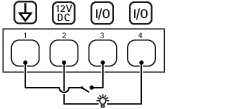
- DC ground
- DC output 12 V
- I/O configured as input
- I/O configured as output
External connector
Two 2-pin terminal blocks for external devices, for example glass break or fire detectors.
UL: The connector has not been evaluated by UL for burglar or fire alarm use.
| Function | Pin | Notes | Specifications |
| DC ground | 1 | 0 V DC | |
| TAMPER | 2 | Digital input – Connect to pin 1 to activate, or leave floating (unconnected) to deactivate. | 0 to max 30 V DC |
| Function | Pin | Notes | Specifications |
| DC ground | 1 | 0 V DC | |
| ALARM | 2 | Digital input – Connect to pin 1 to activate, or leave floating (unconnected) to deactivate. | 0 to max 30 V DC |
Power connector
2-pin terminal block for DC power input. Use a Safety Extra Low Voltage (SELV) compliant limited power source (LPS) with either a rated output power limited to ≤100 W or a rated output current limited to ≤5 A.
| Function | Pin | Notes | Specifications |
| DC ground (GND) | 1 | 0 V DC | |
| DC input | 2 | For powering the device when not using Power over Ethernet. Note: This pin can only be used as power in. | 12 V DC, max 36 W |
UL: DC power to be supplied by a UL 603 listed power supply, depending on application, with appropriate ratings.
Supervised inputs
To use supervised inputs, install end of line resistors according to the diagram below.
Parallel first connection
The resistor values must be 4.7 kΩ and 22 kΩ.
Serial first connection
The resistor values must be the same and possible values are 1 kΩ, 2.2 kΩ, 4.7 kΩ and 10 kΩ.
It is recommended to use twisted and shielded cables. Connect shielding to 0 V DC.
Troubleshooting
Reset to factory default settings
Reset to factory default should be used with caution. A reset to factory default resets all settings, including the IP address, to the factory default values.
To reset the product to the factory default settings:
Disconnect power from the product.
Press and hold the control button while reconnecting power. See Product overview.
Keep the control button pressed for 25 seconds until the status LED indicator turns amber for the second time.
Release the control button. The process is complete when the status LED indicator turns green. If no DHCP server is available on the network, the device IP address will default to one of the following:
Devices with AXIS OS 12.0 and later: Obtained from the link-local address subnet (169.254.0.0/16)
Devices with AXIS OS 11.11 and earlier: 192.168.0.90/24
Use the installation and management software tools, assign an IP address, set the password, and access the product.
You can also reset parameters to factory default through the device’s web interface. Go to Maintenance > Factory default and click Default.
AXIS OS options
Axis offers device software management according to either the active track or the long-term support (LTS) tracks. Being on the active track means continuously getting access to all the latest product features, while the LTS tracks provide a fixed platform with periodic releases focused mainly on bug fixes and security updates.
Using AXIS OS from the active track is recommended if you want to access the newest features, or if you use Axis end-to-end system offerings. The LTS tracks are recommended if you use third-party integrations, which are not continuously validated against the latest active track. With LTS, the products can maintain cybersecurity without introducing any significant functional changes or affecting any existing integrations. For more detailed information about Axis device software strategy, go to axis.com/support/device-software.
Check the current AXIS OS version
AXIS OS determines the functionality of our devices. When you troubleshoot a problem, we recommend that you to start by checking the current AXIS OS version. The latest version might contain a correction that fixes your particular problem.
To check the current AXIS OS version:
Go to the device’s web interface > Status.
Under Device info, see the AXIS OS version.
Upgrade AXIS OS
- When you upgrade the device software, your preconfigured and customized settings are saved. Axis Communications AB can't guarantee that the settings are saved, even if the features are available in the new AXIS OS version.
- Starting from AXIS OS 12.6, you must install every LTS version between your device’s current version and the target version. For example, if the currently installed device software version is AXIS OS 11.2, you have to install the LTS version AXIS OS 11.11 before you can upgrade the device to AXIS OS 12.6. For more information, see AXIS OS Lifecycle guide: Upgrade path.
- Make sure the device remains connected to the power source throughout the upgrade process.
- When you upgrade the device with the latest AXIS OS version in the active track, the product receives the latest functionality available. Always read the upgrade instructions and release notes available with each new release before you upgrade. To find the latest AXIS OS version and the release notes, go to axis.com/support/device-software.
- Because the database of users, groups, credentials, and other data are updated after a AXIS OS upgrade, the first start-up could take a few minutes to complete. The time required is dependent on the amount of data.
Download the AXIS OS file to your computer, available free of charge at axis.com/support/device-software.
Log in to the device as an administrator.
Go to Maintenance > AXIS OS upgrade and click Upgrade.
- When the upgrade has finished, the product restarts automatically.
When the product has been restarted, clear the web browser's cache.
Technical problems and possible solutions
Problems upgrading AXIS OS
AXIS OS upgrade failed If the upgrade fails, the device reloads the previous version. The most common reason is that the wrong AXIS OS file has been uploaded. Check that the name of the AXIS OS file corresponds to your device and try again. |
Problems after AXIS OS upgrade If you experience problems after the upgrade, roll back to the previously installed version from the Maintenance page. |
Problems setting the IP address
Can’t set the IP address
|
Problems accessing the device
Can’t log in when accessing the device from a browser When HTTPS is enabled, make sure that you use the correct protocol (HTTP or HTTPS) when you try to log in. You might need to manually type If you’ve lost the password for the root account, you must reset the device to the factory default settings. For instructions, see Reset to factory default settings. |
The IP address has been changed by DHCP IP addresses obtained from a DHCP server are dynamic and could change. If the IP address has been changed, use AXIS IP Utility or AXIS Device Manager to locate the device on the network. Identify the device using its model or serial number, or by the DNS name (if the name has been configured). If required, you can assign a static IP address manually. For instructions, go to axis.com/support. |
Certificate error when using IEEE 802.1X For authentication to work properly, the date and time settings in the Axis device must be synchronized with an NTP server. Go to System > Date and time. |
The browser isn’t supported For a list of recommended browsers, see Browser support. |
Can’t access the device externally To access the device externally, we recommend you to use one of the following applications for Windows®:
For instructions and download, go to axis.com/vms. |
Problems with MQTT
Can’t connect over port 8883 with MQTT over SSL The firewall blocks traffic that uses port 8883 since it’s regarded insecure. In some cases the server/broker might not provide a specific port for MQTT communication. It might still be possible to use MQTT over a port normally used for HTTP/HTTPS traffic.
|
If you can’t find what you’re looking for here, try the troubleshooting section at axis.com/support.
Contact support
If you need more help, go to axis.com/support.