About this guide
This switch configuration guide is for network administrators configuring and managing AXIS network switches. It provides information on configuring features mainly through the HTTP/HTTPS web interface. Some of the information is given by using the command line interface. This guide applies to the AXIS T85 series (excl. T8504-E) and AXIS D8208-R switch.
Before using this guide, you should have experience with network switches and be familiar with the concepts and terminology of TCP/IP, Ethernet and POE.
This guide does not cover the installation part. You should check and follow the installation guide for each switch model separately. For the user manuals of AXIS Network Switches, see here. For the firmware releases of the network Switches, go to Network Switch Release Notes.
Basic
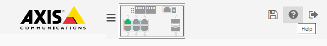
The built-in help manual
The switch has a context-sensitive built-in help. The help provides more detailed information on the product’s basic and advanced features and their settings. To access the help content for any given view, click the question mark at the top right corner. Some help content also includes clickable terms and acronyms that are explained in more detail in the built-in glossary.
Save the configuration
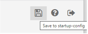
The “Apply” button only saves the configuration to the running-configuration. The configuration will be lost after the switch reboot. To save the configuration changes, we need to copy the settings to the startup-configuration:
In the web interface. Click the floppy icon on the top right corner.
In the CLI interface. Using the below command.
AXIS T85 SW# copy running-config startup-configTo avoid potential conflicts, we recommend that you do the configurations for the new switch before connecting it to the existing network in production.
Access the switch
Management IP
In AXIS T85 Switches, the default Management IP address is the IP address of the VLAN1 interface. When multiple VLAN interfaces are created, you can also access the switch via any of the VLAN interfaces as long as they are reachable.
Username and password
The default username and password are on the product label underneath the switch.
Access the web interface
Accessing the web interface is the easiest way to configure settings or make changes to an Axis Network Switch. The web interface can also give access to a non-Administrator account allowing the user to view the configurations but not allowing any changes.
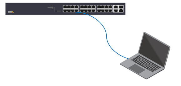
Power on the switch. Connecting the PC to any Ethernet ports on the switch via an ethernet cable.
By default, the switch will get the IP address from the DHCP server. However, if the DHCP server is not available, it will fallback to 192.168.0.254/24. You can also use AXIS IP Utility or AXIS Device Manager to find the product on the network.
Open a browser on your PC. Enter the IP in the address bar and press “Enter”.
The default username and password are on the product label.
Follow the steps in the setup wizard to:
Change the password (recommended for security reasons)
Set the IP address via DHCP or manually
Configure the DHCP server
Set the date & time information
Set the system information
Click Apply.
Re-login using the new password.
Access via SSH
SSH is disabled by default so the users have to log into the webpage to enable it first. To enable it via the web interface:
Choose Advanced > Security > Configuration > Switch > Auth Method > ssh.
Click the dropdown list. Select local.

Click Apply.
Click save configurations.
Below is an example to log into the switch via ssh:
C:\>ssh psadmin@192.168.0.20
psadmin@192.168.0.20's password:
AXIS T85 SW#
Access via the Console port (T8504-R and D8208-R)
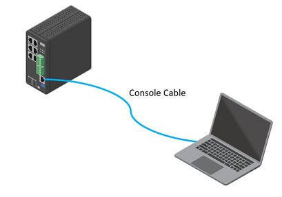
Connect a console cable to the console connector on the switch.
Connect the other end of the console cable to the COM port on your computer. If your PC doesn’t have a COM port, you must use a USB to RS232 adapter.
Open a terminal emulator to manage the switch on your computer.
Find the correct COM port and use these COM port settings:
Baud rate: 115200
Stop bits: 1
Data bits: 8
Parity: N
Flow control: None
Switch configuration
Date and Time
Manual configuration
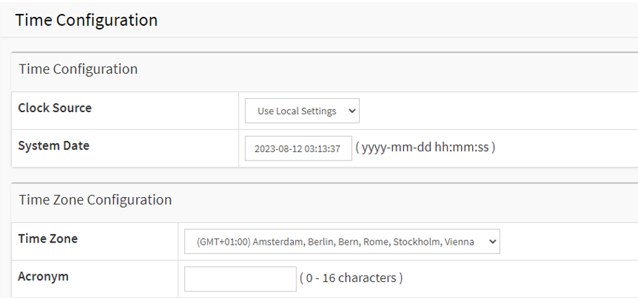
Choose Basic > Date & Time > Configuration. Under “Clock Source”, select “Use local Settings”.
NTP configuration
Choose Basic Settings > Date & Time > NTP server. Input the address of the NTP server. The unit of the time-sync interval is a minute. If set to 60, once the switch finishes the initial time sync with the NTP server, it will sync again with the NTP server every 60 minutes. If your DHCP server assigns the NTP address, please select “Enable” under “Automatic”. Apply the setting.

Choose Basic Settings > Date& Time > Configuration > Time Zone Configuration. Please select the correct Time Zone.
In Time Configuration, Clock Source, select “Use NTP Server” and Apply.
POE
Connect a 60 W camera (AXIS T8504-R)
Choose Basic > Basic Settings > PoE > Power Management.
Under PoE Port Configuration in the PoE Mode drop-down menu, select 2–pair.
If you want to assign the same mode for all ports, select the mode on the Port row marked with an asterisk (*)

If you want to assign the mode for certain ports only, select the mode for selected ports on the respective Port number rows.
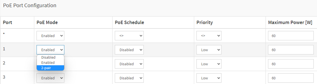
Click Apply to save the configuration.
Set a POE Schedule
If you have a certain time frame where you want the switch to provide PoE, for example, to your cameras, it can be useful to create a PoE schedule and assign it to one or more PoE ports. You can create up to 16 PoE schedule profiles. To create a PoE schedule:
Choose Advanced > PoE > Configuration > Schedule Profile.
In the Profile drop-down menu, select a number for the profile.
Change the default profile name as needed.
To specify when you want PoE to switch on, select hours (HH) and minutes (MM) in the Start Time drop-down menu.
To specify when you want PoE to switch on, select hours (HH) and minutes (MM) in the Start Time drop-down menu.
If you want to use the same schedule for all days of the week, select the start and end times on the Week Day row marked with an asterisk (*).
If you want to use the same schedule for certain days of the week only, select the start and end times for selected days on the respective Week Day rows.
Click Apply to save the configuration.
To assign the created PoE schedule to one or more PoE ports:
Go to Basic > Basic Settings > PoE > Power Management.
Under PoE Port Configuration in the PoE Schedule drop-down menu, select the number of the specified PoE schedule profile.
If you want to assign the same profile for all ports, select the profile number on the Port row marked with an asterisk (*).
If you want to assign the same profile for certain ports only, select the profile numbers for selected ports on the respective Port number rows.
Click Apply to save the settings.
Port Configuration
Speed and duplex
It is critical to properly configure both speed and duplex on the network interface for a reliable network connection. A common issue is the mismatch of speed and duplex on the Interfaces.
When the switches connect with other devices, we recommend that both interfaces on the link should have the same settings.
To change the speed and duplex settings of the switch ports. Choose Advanced > Ports > Configuration.
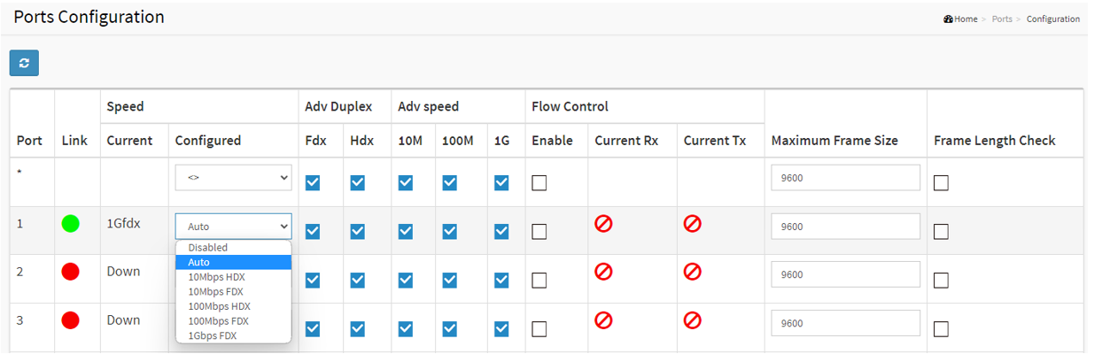
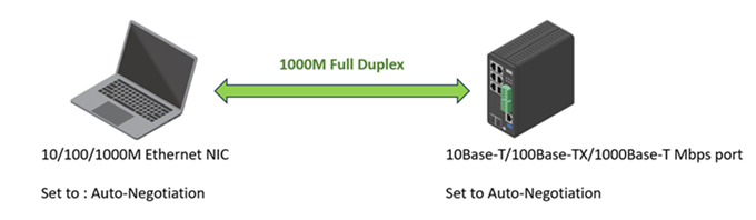
In the example below, both devices' network interfaces are configured to “Auto-Negotiation”. The link is 1000M/full duplex after successful negotiation.
However, you may need to specify the speed and duplex mode under certain scenarios manually:
When the peer device does not support the Auto-Negotiation function
the device cannot be connected after configuring to use the Auto-Negotiation
the interface has a large number of wrong packets or packet loss
SFP
When an SFP module is connected to the switch, you can check the SFP module information by Choose Advanced > Ports > Status > SFP Port info.
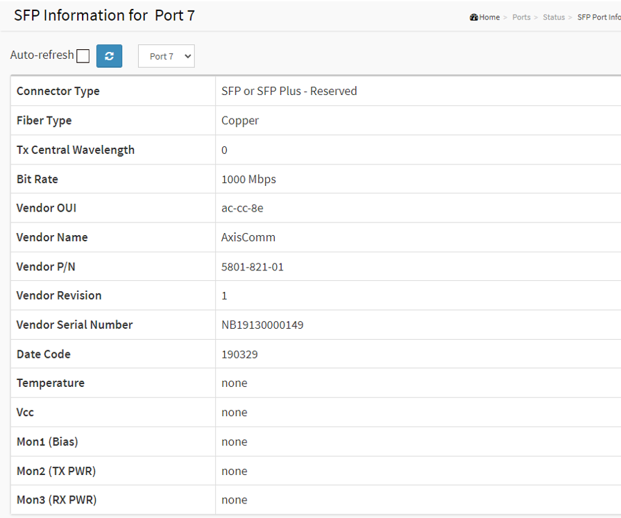
In order to ensure proper operation of Axis products with SFP support, it is recommended that all Axis supported SFP devices utilize Axis SFP transceivers which have been fully tested for consistent behavior in Axis SFP supported devices. Due to varying performance of third-party SFP transceivers, use would be at own risk and may result in limited network performance and/or no connection at all. Axis can only guarantee full support for Axis supplied SFP transceiver modules.
VLAN
VLANS are typically used on large networks to create multiple broadcast domains, but they can also be used to segregate network traffic. For example, video traffic can be part of one VLAN, and other network traffic can be part of another.
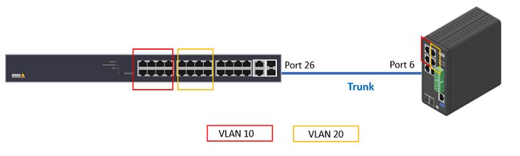
Create VLANs
In the below example, we create additional 2 VLANs, VLAN 10 and VLAN 20. And create trunk ports on both Switches.
Choose Advanced > VLANs > Configurations.
Under “Allowed Access VLANs”, enter the VLANs you want to create.

To assign a created VLAN ID to a given port under Port VLAN Configuration, enter the ID to the Port VLAN field.

To Configure a port as Trunk Port. In the dropdown list of “Mode”, select “Trunk”. Make sure the “Allowed VLANs” field is correct.
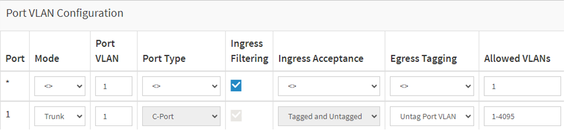
Click Apply to save the settings.
Do the same configurations on the other switch.
Inter VLAN routing via AXIS Switch
Access the cameras in different VLANs. If you don’t have a router in your network, you can enable the Router mode in the AXIS Switches.
Choose Advanced > System > Configuration > IP. Under “Mode”, select “Router”.
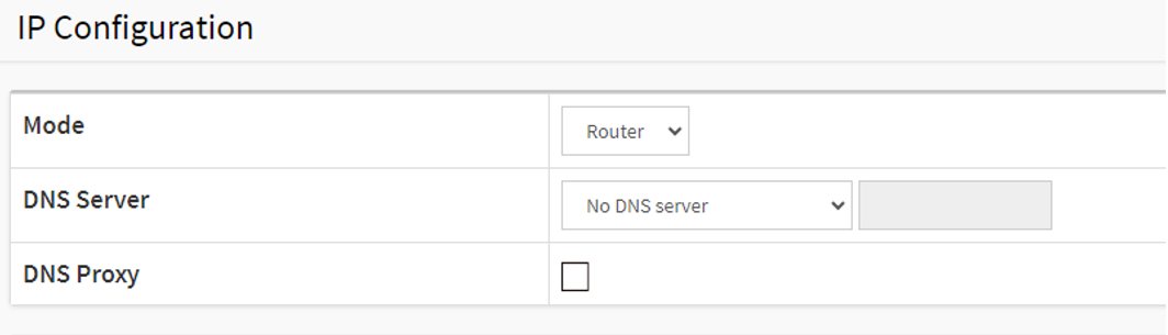
In the same page, make sure all the VLAN interfaces have been configured.

Set the Gateway for the devices.
Cameras in VLAN 20, gateway: 192.168.2.1
Cameras in VLAN 30, gateway: 192.168.3.1
PC is in VLAN 1, gateway: 192.168.0.101
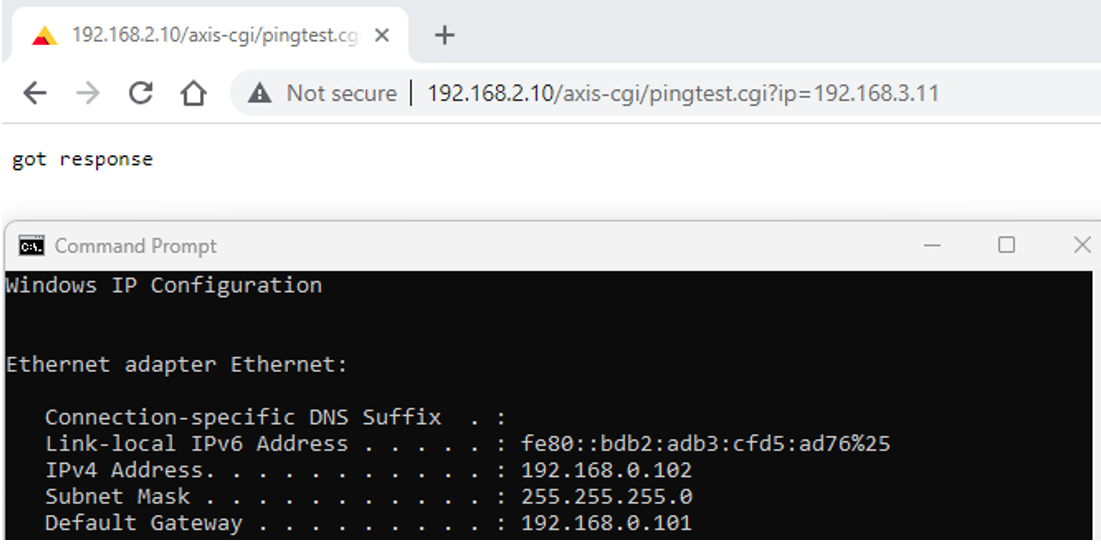
Use Ping to test the connectivity between VLANs. In this example, the IP of the PC is 192.168.0.102 which sits in VLAN 1. From this PC, we open a browser and issue a VAPIX command to camera (192.168.2.10) in VLAN 20 to Ping another camera (192.168.3.11) in VLAN 30.
Spanning Tree Protocol
When deploying Layer 2 network, redundant paths are normally configured. Although a redundant path can protect against single-point failure, it can also lead to a loop and eventually cause a network broadcast storm.
Spanning Tree Protocol(STP) is designed to prevent loops on Layer 2 networks when a redundant link exists. The common STP protocols are
The original STP, defined in IEEE 802.1D
Rapid STP or RSTP, defined in IEEE 802.1w. It is an improved STP version with a faster convergence time when link failure happens.
Multiple STP or MSTP, defined in IEEE 802.1s. It can group multiple VLANs into a spanning tree instance and create multiple instances. In addition to that, it also provides load balancing when separating the instances into different paths on the network.

STP
Choose Advanced > Spanning Tree > Configuration > Bridge Settings > Basic Settings > Protocol Version. In the dropdown menu, select STP.
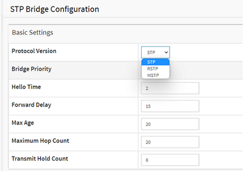
Click Apply to save the settings.
Choose Advanced > Spanning Tree > Configuration > CIST Ports > CIST Normal Port Configuration. Make sure that “STP Enabled” is selected for the switches’ ports as follows:
Switch 1: Port 25 and Port 26
Switch 2: Port 5 and Port 6
Switch 3: Port 5 and Port 6
Click Apply to save the settings.
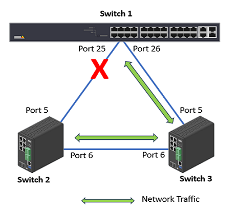
Check the port status. Choose Advanced > Spanning Tree > Status > Port Status.
Switch 1: Port 25 (Discarding), Port 26 (Forwarding)
Switch 2: Port 5 (Forwarding), Port 6 (Forwarding)
Switch 3: Port 5 (Forwarding), Port 6 (Forwarding)
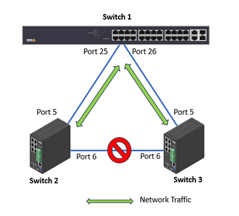
Now let’s remove the network cable between Switch 2 and Switch 3.
Check the port status. Choose Advanced > Spanning Tree > Status > Port Status.
Switch 1: Port 25 (Forwarding), Port 26 (Forwarding)
Switch 2: Port 5 (Forwarding), Port 6 (Discarding)
Switch 3: Port 5 (Forwarding), Port 6 (Discarding)
RSTP
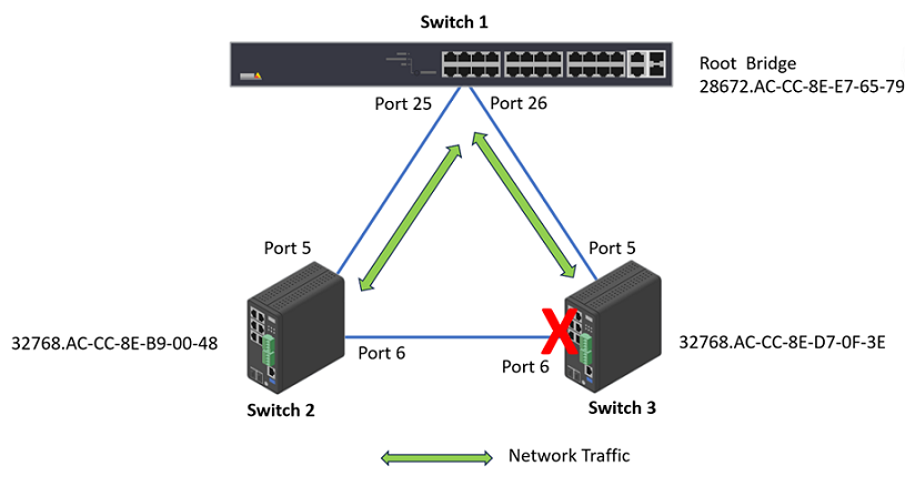
In this example, RTSP is used as the STP protocol. And we make the Switch 1 as the root switch so that no ports on it will be in Discarding status.
Choose Advanced > Spanning Tree > Configuration > Bridge Settings > Basic Settings > Protocol Version. In the dropdown menu, select “RTSP”.
To make Switch 1 become the root bridge, we lower the “Bridge Priority” to 28672.
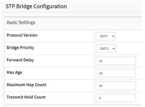
Click Apply to save the setting.
On both Switch 2 and Switch 3, change the Protocol Version to “RTSP”. Click Apply to save the settings.
Choose Advanced > Spanning Tree > Configuration > CIST Ports > CIST Normal Port Configuration. Make sure that “STP Enabled” is selected for the switches’ ports as follows:
Switch 1: Port 25 and Port 26
Switch 2: Port 5 and Port 6
Switch 3: Port 5 and Port 6
To check the STP status. Choose Advanced > Spanning Tree > Status > Bridge Status. Click “CIST”. We can see that Switch 1 is the Root Bridge. And on Switch 3, Port 6 is in Discarding State.

Rapid Ring
The Rapid Ring is a redundancy protocol that used to recover the network from critical link failure. Meanwhile, it can protect the network from loops. Comparing with the Spanning Tree Protocol defined by IEEE, Rapid Ring is much faster.
The Rapid Ring is only available in the Industrial Switches (T8504-R and D8208-R). It supports several different applications, for example, Single Ring, Ring to Ring.
Only one redundant protocol can be used at the same time, before you want to use Rapid Ring, you have to disable the Spanning Tree.
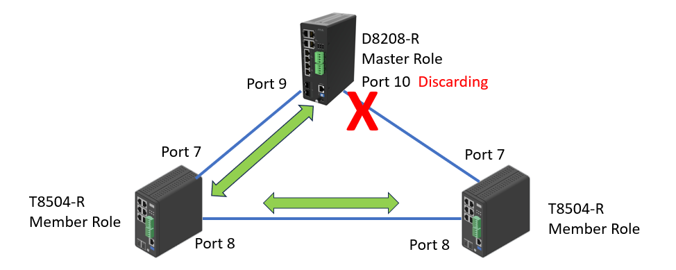
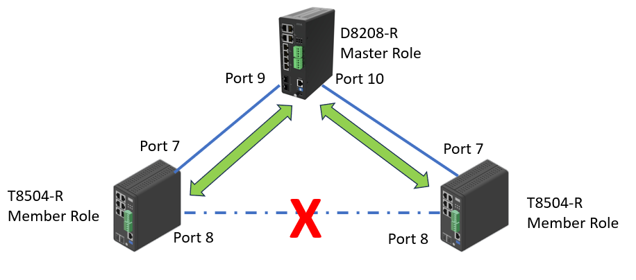
The Single Ring is the most common ring to use. To configure Single Ring, one of the switches must be the “Master role” and the rest switches must be “Member role”. Only one switch can be the master role.

The Rapid Ring configuration is not available in the web interface on T8504-R. To configure it, we need to do it via the command line. In this example, the two T8504-R switches are members.
AXIS T85 SW # configure terminal
AXIS T85 SW (config)# rapid-ring entry 1 role member port1 GigabitEthernet 1/7 port2 GigabitEthernet 1/8
To configure Rapid Ring on D8208-R
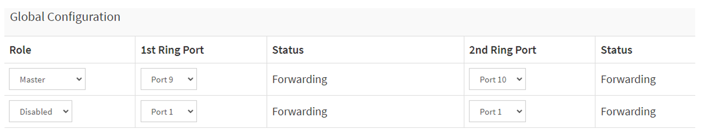
Choose Advanced > Rapid Ring.
Select “Master” as the role and select the 2 ports respectively.
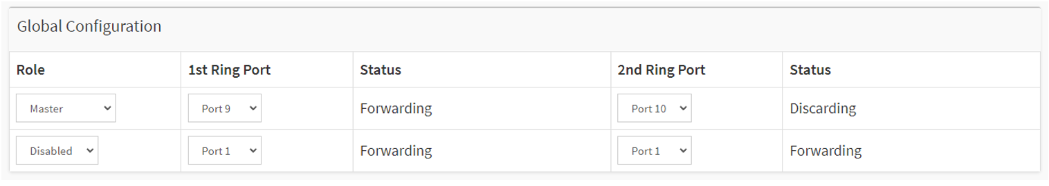
Click “Apply” to save the configuration.
To verify the configuration, we can check the port Status. In this example, port 9 is “Forwarding” and Port 10 is “Discarding”. If the switch is a Master role, by default 1st Ring Port will be the active path and 2nd Ring Port as backup path.
Now we disconnect the link between the two T8504-R switches. From D8208-R, we can see both port 9 and 10 are now in “Forwarding” status.
To show the Rapid Ring Status on the T8504-R switch, please use the below command:
AXIS T85 SW #  show rapid-ring
Entry Index               : 1
Rapid Ring Role           : Member
Rapid Ring Port 1         : 7
Rapid Ring Port 2         : 8
Rapid Ring Port 1 State   : Forwarding
Rapid Ring Port 2 State   : Discarding
Entry Index               : 2
Rapid Ring Role           : Disabled
Rapid Ring Port 1         : 1
Rapid Ring Port 2         : 1
Rapid Ring Port 1 State   : Forwarding
Rapid Ring Port 2 State   : Forwarding
Ring-to-Ring Role         : Disabled
Ring-to-Ring Port         : 1
Ring-to-Ring Port State   : Forwarding
The industrial switches come with the DIP Switch. Please keep both “RM” and “RC” in “ON” state which is also the default state. Otherwise, all Rapid Ring, Spanning Tree software configurations via web interface and command line are deactivated.
Ethernet Channels
Ethernet channel, also known as Link Aggregation Control Protocol(LACP), is a technique used to bundle multiple physical switch ports between two switches into one logical port.
There are several advantages of doing this:
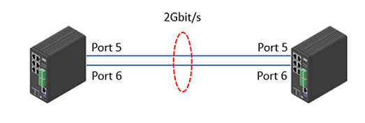
Increased bandwidth. In the example, port 25 and 26 speed is 1Gbit/s. After bundling, the total bandwidth between Switch 1 and Switch 2 will be 2Gbits/s.
Load balancing. The traffic between Switch 1 and Switch 2 will be distributed through the 2 links.
Redundancy. If one physical link is down, the Ethernet Channel will still work on the remaining link.
Please don’t connect multiple network cables between the two switches before proper configurations to avoid loop. Only full-duplex ports can join an aggregation and ports must be in the same speed in each group.
Static Ethernet Channel
Choose Advanced > Aggregation > Configuration > Static > Aggregation Group Configuration. In this example, we put both ports 5 & 6 into Group 1.
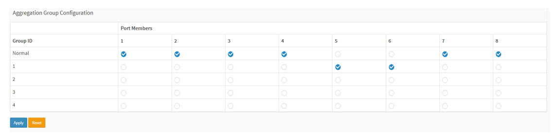
Click Apply to save the settings.
Do the same setup on the other switch.
Verify the status. Choose Advanced > Aggregation > Status > Aggregation. The “Type” is Static.

LACP
Choose Advanced > Aggregation > Configuration > LACP, In this example, we select both ports 5 and 6.

Click Apply to save the settings.
Do the same settings on the other switch.
Verify the status. Choose Advanced > Aggregation > Status > LACP > System Status.

You can also see the aggregation status under Advanced > Aggregation > Status > Aggregation. The “Type” is LACP.

Access the switch via HTTPS
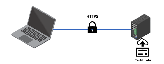
By enabling HTTPS, all the data or administrative tasks you performed on the switch will be encrypted. Make it very difficult for unauthorized users to read the data.
The AXIS Switch supports RSA certificate only. The supported RSA key lengths are 1024 bit, 2048 bit and 4096 bit. However, the 4096 bit key length may affect the performance of the switch.
To upload your own certificate via the Web Browser:
Choose Advanced > Security > Configuration > Switch > HTTPS.
Select “upload” for “Certificate Maintain”. The certificate should be in PEM format.
Fill in the Passphrase for the certificate file if your uploaded certificate is protected by a specific passphrase.
Select “Web Browser” for the “Certificate upload” method.
Under “File Upload”, click “Choose File” to select and upload a certificate PEM file into the switch. The file should contain the certificate and private key together. Click “Apply” to save the settings.

Choose Advanced > Security > Configuration > Switch > Auth Method. Under “Authentication Method” , for “https”, select “local”.
When HTTPS is enabled, enable HTTP automatic redirect or disable it on the switch.

Click “Apply” to save the settings.
Verify the connection.

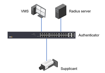
IEEE 802.1X Configuration
IEEE 802.1X is an IEEE standard for port-based network access control (“port” means the physical connection to the LAN infrastructure). It is part of the IEEE 802.1 group of networking protocols and provides an authentication mechanism for devices to connect to a LAN, either establishing a connection or preventing the connection if authentication fails. For more information, read it at AXIS OS Lifecycle guide.
In order to use port-based authentication, the network must be equipped with a RADIUS server and a network switch with support for IEEE 802.1X. The RADIUS server needs to know all the trusted “clients”. Where “clients” are the managed switches in this case. You may need to contact the IT Administrator for the information and configuration.
To Configure the feature in AXIS Switches:
Disable Spanning Tree Protocol on the port for 802.1x authentication. Choose Advanced > Spanning Tree > Configuration> CIST ports. Uncheck the ports and apply the configuration.
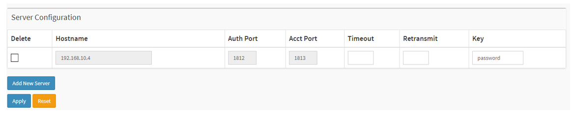
Choose Advanced > Security > AAA > RADIUS > Server Configuration. Click “Add New Server”. Fill in the IP address or Hostname of the RADIUS server. The default port is 1812. Fill in the Key which is the password for the switch to authenticate against the RADIUS server. Click “Apply” to save the configuration.
Choose Advanced > Security > Configuration > Network > NAS. Under “System Configuration”, Set the “Mode” to Enabled.

Under “Port Configuration”, enable “Port-based 802.1x” for the respective ports. In the below example, we enabled the 802.1x authentication for port 3.

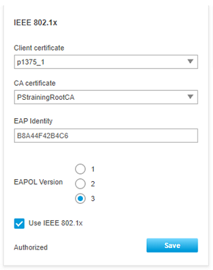
Verify the authentication status from the devices web page. It shows “Authorized” at the bottom.
Access Control List
The access control list is a powerful tool to filter the traffic on the switch. It includes multiple rules in sequential order.
The Axis Switch can only inspect the ingress traffic on the ports. When a frame or a packet arrives at the switch, it will check the frame against the rules in the ACL. The frame/packet will be accepted once it matches a permit rule or dropped soon as it matches a deny rule. If no rule is matched, the switch will accept the packet.
The network administrator can use ACL to protect the network from unwanted network traffic. To configure the ACL, Choose Advanced > Security > Network > ACL > Access Control List. Click the “+”icon.
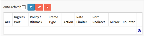
Below are some examples.
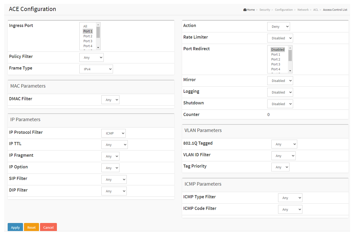
Drop the ICMP packets arriving at port 1.
Ingress port: Port 1
Frame Type: IPv4
IP Protocol: ICMP
Action: Deny
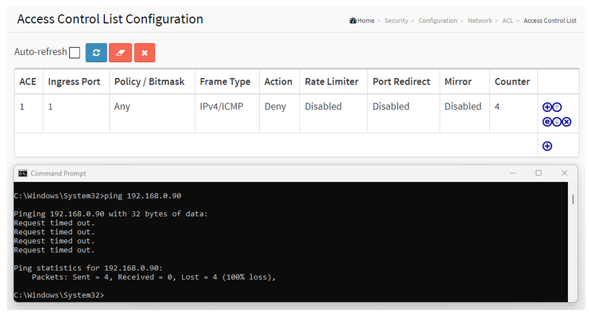
To verify the ACL, we connect a PC to port 1 and ping the camera with 192.168.0.90. The ping fails and the count is 4.
Drop the broadcast traffic on port 1
Ingress port: Port 1
Frame Type: Ethernet Type
DMAC Filter: BC
Action: Deny

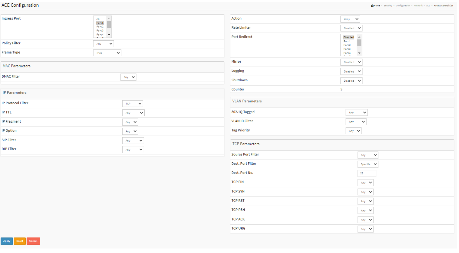
Drop the ssh traffic arriving port 1
Ingress port: Port 1
Frame Type: IPv4
IP Protocol Filter: TCP
Dest.Port Filter: Specific
Dest.Port No. 22
IGMP Snooping
In the layer 2 network, when a frame is received by the switch port. The switch will learn and save the source MAC address to the MAC address table. Then the switch checks the destination MAC address and lookup the MAC address table to find out which port should forward this frame. If there is no entry in the MAC address table, the switch will normally flood this frame to all the ports except the port that receives the frame.
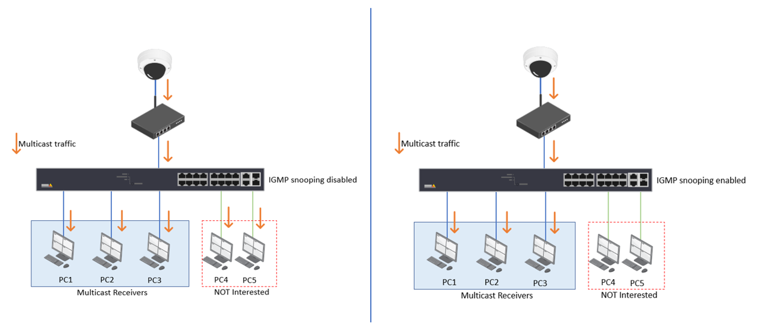
In a multicast network, the multicast frames have a destination MAC address starting with 01005e. However, this MAC address has never been used as a source MAC address so the switch has never learned about it and saves it into the MAC address table. Due to this, the switch will flood this multicast traffic to all the ports. IGMP snooping helps to suppress the unnecessary flooding of multicast traffic in the layer 2 networks.
When a receiver is interested in receiving multicast traffic, the receiver will send out an IGMP membership report message to the last-hop router. As the name implies, the switch will actively snoop the IGMP packets and use the content in the packets to build a multicast forwarding table. The table includes the multicast groups and the interfaces that the members of each group are connected to. By checking this table, the switch will not forward the multicast traffic to unwanted receivers. Please be aware that IGMP snooping is not a feature of the IGMP protocol.
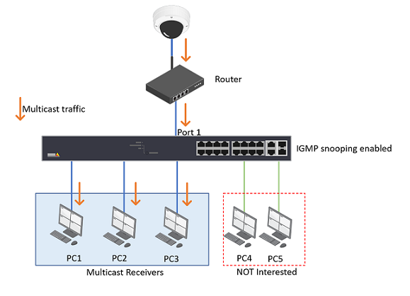
Configure IGMP with a multicast-enabled router
If your network has a multicast-enabled router like the one below, and on the switch, port 1 is connected to the router.
Choose Advanced > IPMC > Configuration > IGMP Snooping > Basic Configuration.
Check “Snooping Enabled”.
Uncheck “Unregistered IPMCv4 Flooding Enabled”.
Under Port Related Configuration, Select Port 1 as the Router Port.
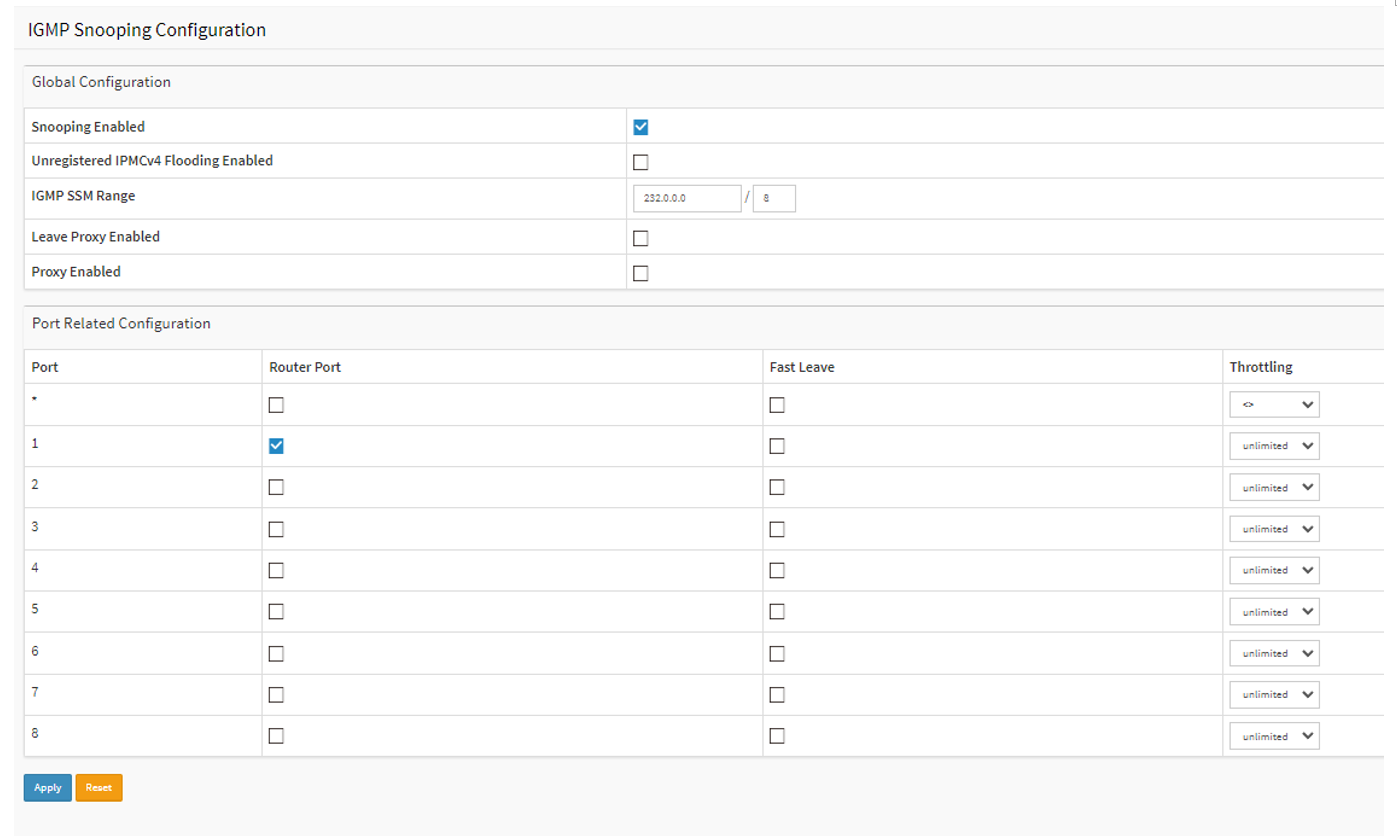
Click Apply to save the settings.
Configure IGMP in a pure layer 2 environment
If your network only has layer 2 switches without a router.
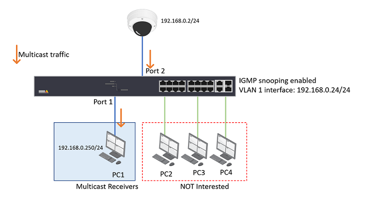
Though a multicast router is more appropriate for multicast handling. Sometimes, the network may not have a router. Then the layer 2 switch will act as an IGMP querier which can fulfill part of that role.
Choose Advanced > IPMC > Configuration > IGMP Snooping > Basic Configuration.
Check “Snooping Enabled”.
Uncheck “Unregistered IPMCv4 Flooding Enabled”
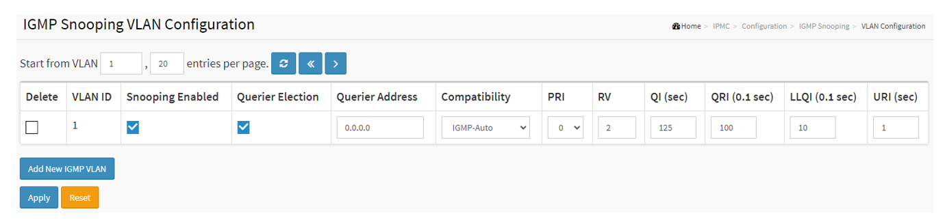
Choose Advanced > IPMC > Configuration > IGMP Snooping > VLAN Configuration. Click “Add New IGMP VLAN”.
Fill in the information needed
VLAN ID: 1 (in this example, all the devices are sitting in VLAN 1)
Snooping Enabled: check
Querier Address: 0.0.0.0 (When the Querier address is not set, the system uses IPv4 management address of the IP interface associated with this VLAN, in this example, it will use the VLAN 1 interface IP 192.168.0.24/24)
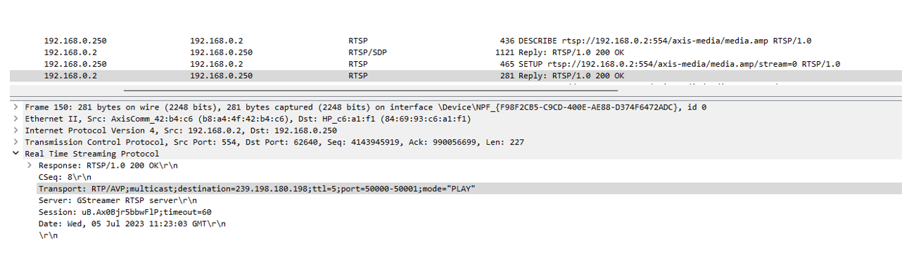
From PC1, we use VLC to receive multicast video from the camera. After RTSP negation, the multicast address group information is as below:
Multicast address: 239.198.180.198
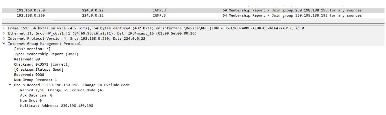
PC 1 sends out IGMP Membership Report to group 239.198.180.198.
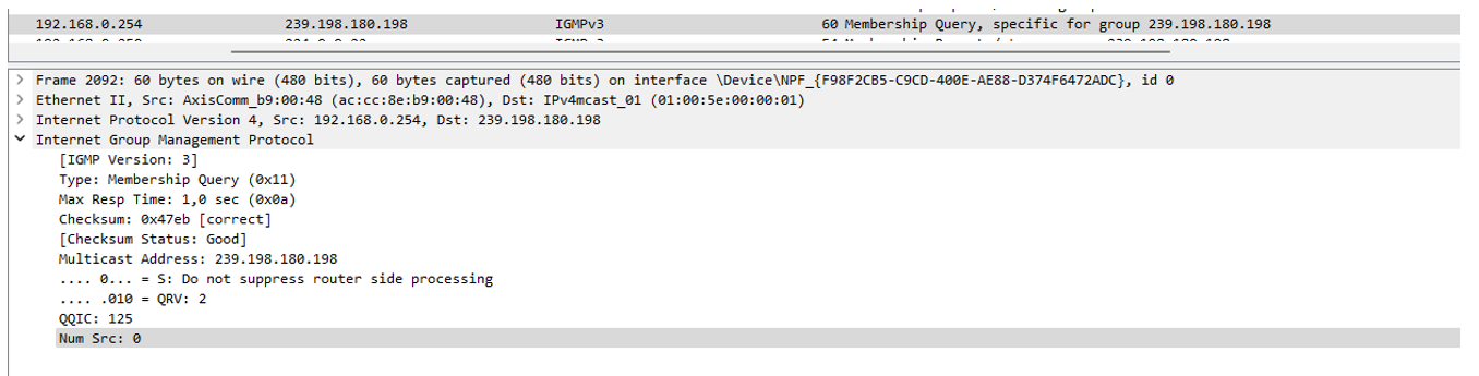
From the Wireshark trace, we can see the switch (the IGMP querier) sends out IGMP Membership query message to group 239.198.180.198.
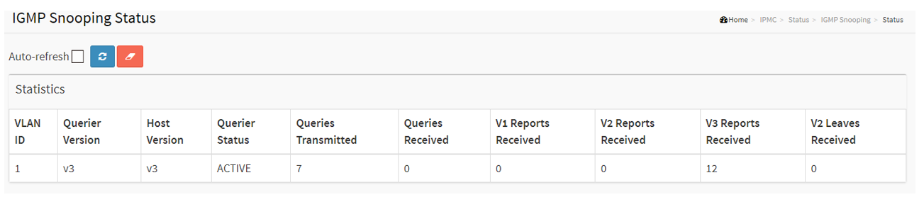
From the switch webpage, Choose Advanced > IPMC > Status > IGMP Snooping > Status. We can see the switch sends out queriers and receives reports.
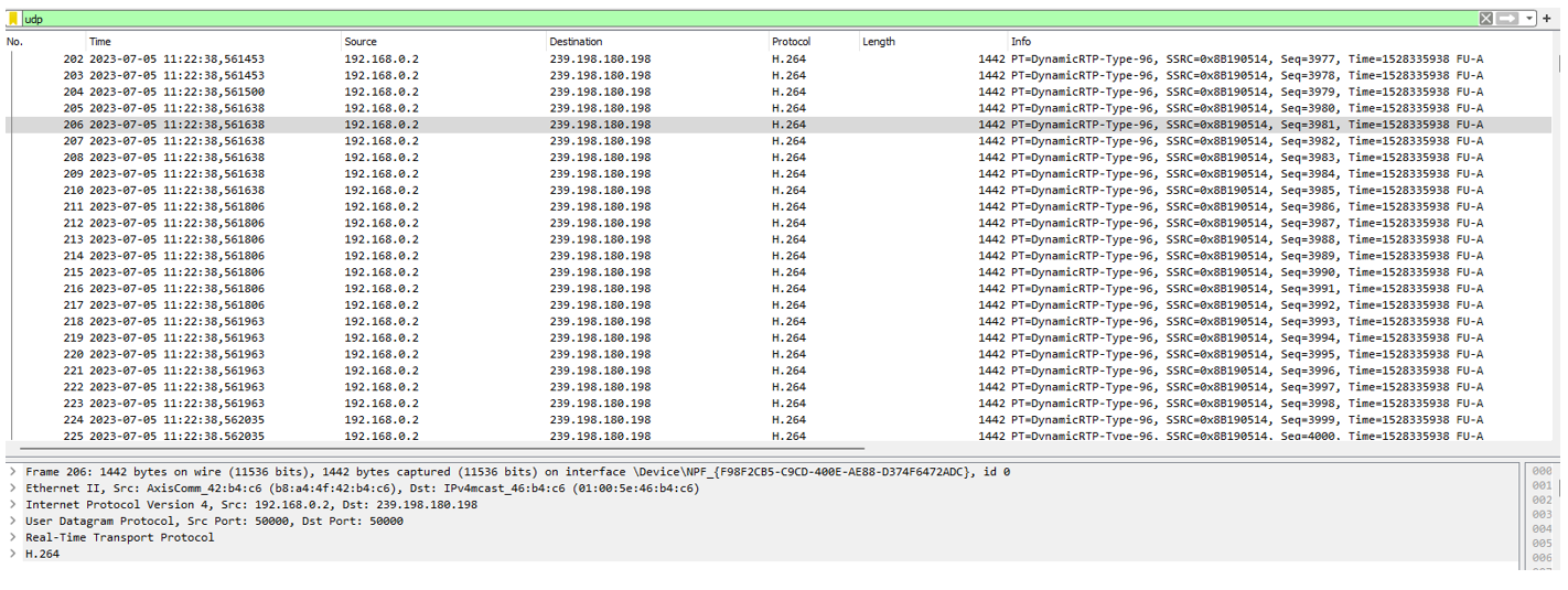
Checking the Wireshark trace, we can see the camera is sending multicast video stream to the group address 239.198.180.198.
Check the IGMP Snooping group information on the switch. Choose Advanced > IPMC > Status > IGMP Snooping > Status > Groups Information. We can see port 1 and 2 belongs to multicast group 239.198.180.198.

Syslog
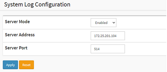
Syslog is a standard for message logging in IT devices. It is increasingly required in IT business applications and governance to facilitate, store, monitor and analyze audit logs from IT devices. The AXIS network switch can use the syslog protocol to send log messages to a server.
Choose Advanced > System > Configuration > Log.
SNMP
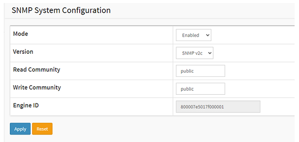
SNMP allows network management operators to use standard SNMP tools to monitor the status of Axis switches.
Basic Configuration:
Choose Advanced > Security > Switch > SNMP > System.
SNMP Trap
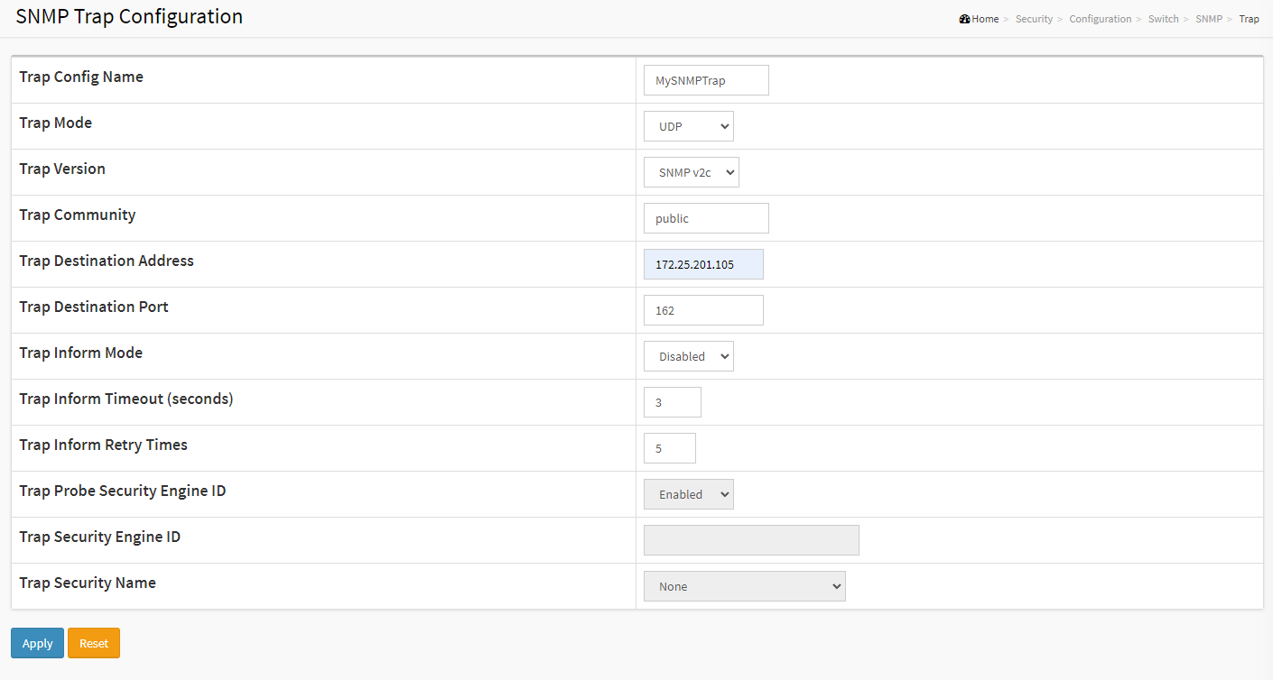
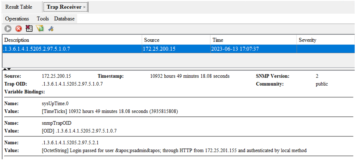
SNMP trap messages are used to inform the SNMP manager when an event occurs. In the below example, I will show you how to notify the SNMP manager when a user logs into the switch.
Choose Advanced > Security > Switch > SNMP > Trap and click Add new Entry. Enter the information needed and Click Apply.
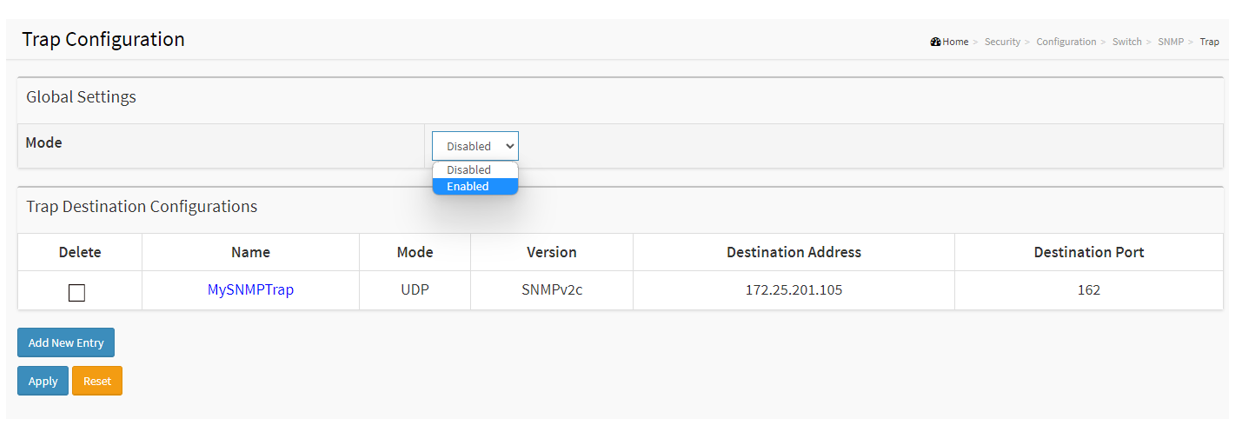
Enable the Trap operation. Select Enable and click Apply.
Choose Advanced > Security > Switch > SNMP > Trap Event Severity. Select Login and Logout. And click Apply.

When a user logs into the switch, the SNMP manager receives a notification
Port Mirroring
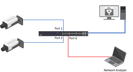
The network switch port mirroring allows the network administrator to monitor and analyze the network traffic. The switch copies the network traffic from one or more ports to a specific port for analysis.
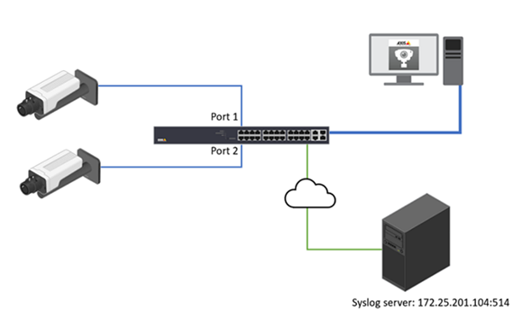
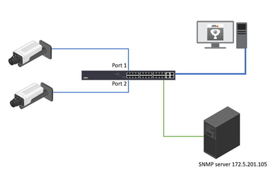
The Network Analyzer is attached to Port 6. To monitor both ingress and egress traffic on port 1 and 2.
T8504-R, web interface.
Choose Advanced > Ports > Mirroring.

Port to mirror to, select port 6. For ports 1 and 2, select “Enable” for the Mode.

Click Apply to save.
Optional. On T8504-R, this feature can be configured by CLI also.
AXIS T85 SW(config)# monitor session 1
AXIS T85 SW(config)# monitor session 1 source interface GigabitEthernet 1/1-2 both
AXIS T85 SW(config)# monitor session 1 destination interface GigabitEthernet 1/6
For T8508, T8516 and T8524, this feature can only be configured via CLI. Below are the example commands:
AXIS T85 SW(config)# monitor session 1
AXIS T85 SW(config)# monitor source interface GigabitEthernet 1/1-2 both
AXIS T85 SW(config)# monitor destination interface GigabitEthernet 1/6
Switch Topology View
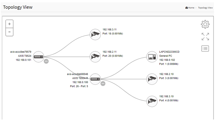
The topology view displays all the network devices connected to the switches. It is mainly designed for star, tree, and ring topology.
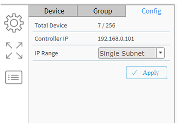
It supports up to 256 devices within 4 subnets.
Device list only supports displaying up to 256 devices including the offline devices in the list. To show the new devices connected to the network, users must manually remove offline devices.
IP range on the config tab of the topology view only supports /24 as the subnet mask.
All switches’ gateway should be properly configured (Gateway and the switch’s one of IP interface at the same network segment).
When LACP is configured, the topology view may not work properly.
Enable or Disable the topology view
The topology view feature is enabled by default. It can only be disabled via the command line interface.
AXIS T85 SW(config)# conf t
AXIS T85 SW(config)# dms service-mode disabled
To enable the topology view feature again:
AXIS T85 SW(config)# conf t
AXIS T85 SW(config)# dms service-mode enabled
Configure the topology view when multiple VLANs exit
The topology view's controller will be elected when multiple switches are interconnected. The controller switch controls the topology view and is in charge of syncing all the necessary information. When multiple subnets or VLANs are involved, the controller must be configured with multiple IP interfaces for VLANs for polling end devices.
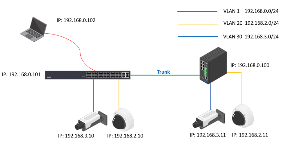
Log into the switches and create VLAN 1, VLAN 20 and VLAN 30 respectively. Assign the ports to the VLANS according to the network design.
Now all the cameras will not be displayed in Topology View.

Figure out the Controller switch in the network. Click the Cogwheel in the Topology View > Config. The “Controller IP” is shown there. In our example, both 2 switches show “192.168.0.11”.
If you want to promote the other switch to the Controller, please log into that switch CLI interface via ssh or console cable and use below command.
Config the VLAN interfaces on the Controller switch. Choose Advanced > System > Configuration > IP. Under IP Interfaces, click “Add interface”. In this example, we need to create VLAN interfaces 20 and 30.
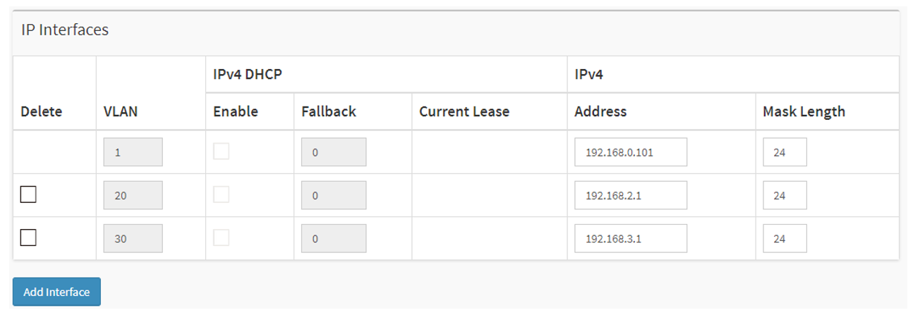
Click Apply to save settings.
After a while, all the cameras in different VLANs will be displayed in the Topology View.
AXIS T85 SW # configure terminal
AXIS T85 SW (config)# dms service-mode enabled priority highThe command line interface
Basic commands
The CLI is divided into several modes. If a user has enough privilege to run a particular command, the user has to run the command in the correct mode. To see the commands of the mode, please input “?” after the system prompt, then all commands will be listed in the screen. The command modes are listed as below.
To check the current running configuration:
To enter the configuration mode:
Exit the configuration mode:
Logout:
AXIS T85 SW # show running-configAXIS T85 SW # configure terminal
AXIS T85 SW (config)#AXIS T85 SW (config)# exit
AXIS T85 SW#AXIS T85 SW# exit
Please press enter after the “exit” command
AXIS T85 SW#exitConnection to 172.25.200.24 closed by remote host.
Connection to 172.25.200.24 closed.Banner
The banner message is commonly used to display warnings or informational messages. There are 3 different types of banner messages: message of the day(MOTD), Login Banner and exec banner.
To configure the MOTD
The MOTD will be displayed next login.
To configure the banner message when entering the EXEC mode.
The next message will be displayed the next time entering the exec mode.
AXIS T85 SW (config)# banner motd "--Welcome To the AXIS Switch Integration Guide--"C:\>ssh psadmin@192.168.0.20
psadmin@192.168.0.20's password:
--Welcome To the AXIS Switch Integration Guide--
AXIS T85 SW#AXIS T85(config)# banner exec L
Enter TEXT message. End with the character 'L'.
######################################################################
The guide is intended for use by network administrators who are responsible
for operating and maintaining network equipment; consequently, it assumes
a basic working knowledge of general switch functions, the Internet Protocol
(IP), and Simple Network Management Protocol (SNMP).
###################################################################### LPress ENTER to get started
Username: root
Password:
######################################################################
The guide is intended for use by network administrators who are responsible
for operating and maintaining network equipment; consequently, it assumes
a basic working knowledge of general switch functions, the Internet Protocol
(IP), and Simple Network Management Protocol (SNMP).
######################################################################
AXIS T85#CLI documentation
You can find a complete list of CLI commands in the guides below.
| Model | Guide |
| T8508 T8516 T8524 | Download |
| T8504-R | Download |
| D8208-R | Download |
| D8248 | Download |
| D8308 | Download |
Maintenance
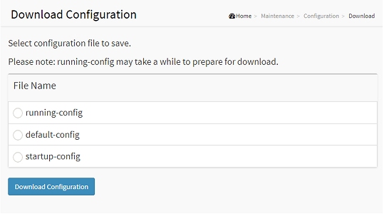
Backup the current configurations
To backup the switch configurations, Choose Advanced > Maintenance > Configuration > Download. Select the files you want to download and click “Download Configuration”. Download of running-config may take a little while to complete, as the file must be prepared for download.
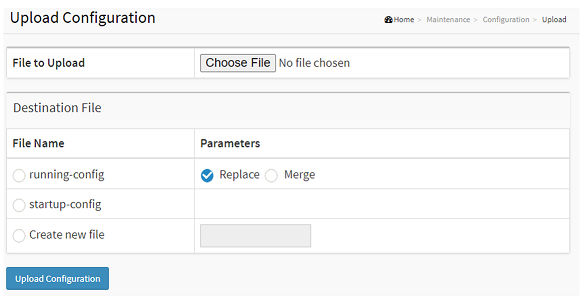
Restore the configurations
To restore the configuration by uploading a configuration file that is saved locally, Choose Advanced > Maintenance > Configuration > Upload. If the destination is running-config, the file will be applied to the switch configuration.
This can be done in two ways:
Replace mode: The current configuration is fully replaced with the configuration in the uploaded file.
Merge mode: The uploaded file is merged into running-config.
Troubleshooting
Basic troubleshooting steps for common issues
The switch has been installed properly according to the installation guide.
Check the LED lights status on the switches. For more information about the LED lights, please visit https://help.axis.com for the user manuals.
If the power is down, please check the power source and make sure the power cable is in good condition and properly connected.
If the link is down, check
If the network cable is properly connected or in good condition
Check the port configuration. For example the port has been administratively shutdown. Or check the speed and duplex settings.
Specific features not working as expected
Check the Network Topology design.
Follow the network design and make sure the configurations have been done correctly.
Verify the status of the feature.
Contact the Technical Support
When contacting the Technical Support, please make sure you have prepared:
Clear description of the issue you are experiencing.
The troubleshooting steps have been taken.
A network design topology
Server report from the switch. You can download the server reports from Basic > Maintenance > Server Reports.
Other information would be helpful to understand your issues. For example, a photo or a short video clip.