About the application
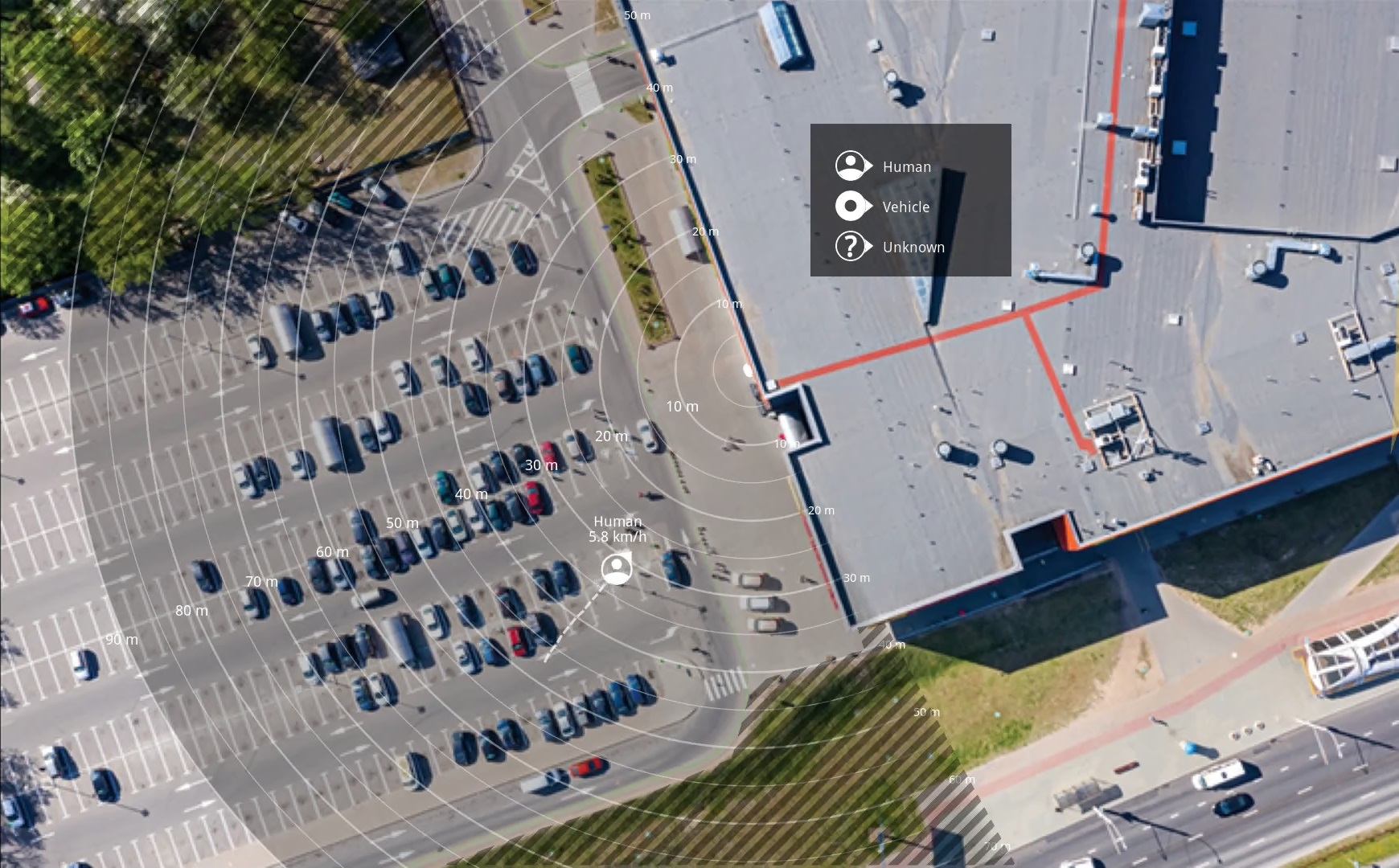
AXIS Speed Monitor visualizes the speed of vehicles in a radar detection zone in the camera's live view, and logs the radar tracks on an SD card for statistical processing. The application requires an Axis camera and an Axis radar, or just an Axis radar. For a list of compatible Axis cameras, see axis.com/products/axis-speed-monitor#compatible-products.
You can use the application in standalone radar installations without cameras, for example due to privacy concerns, or for statistical purposes only. The speed will then be visualized in the radar's live view.
The radar, or radar-video fusion camera, needs to be mounted and configured according to the installation guide and user manual. For more information, see the user documentation for each device:
To be able to log statistics, install the SD card in the device where the application is installed.
Get started
Calibrate the radar
When the radar is installed, the default live view of the radar will show the radar coverage and any detected movement, and you can add scenarios and rules right away. Before you set up the connection with the radar and configure the application overlays, calibrate the radar for the scene.
Check that the mounting height of the radar corresponds with the radar’s set height in the camera’s web interface. If the radar is mounted on a different height, you need to calibrate the radar to compensate for the mounting height.
To calibrate the radar:
Log in to the camera’s web interface.
Go to Radar > Settings > General and enter the mounting height.
In Radar > Settings > Detection, turn on Ignore swaying objects to exclude bushes, trees and signs from your scenarios. Make sure there is no road sign just in front of the radar.
Map calibration
To make it easier to see where objects are moving, upload a reference map, for example a ground plan or an aerial photo, that shows the area covered by the radar.
- Image requirements:
Supported file formats are jpeg and png.
The image can be cropped in the radar.
The orientation is not important, since the radar coverage shape will move to adapt to the image during calibration.
Go to Radar > Map calibration and follow the setup assistant to upload and calibrate your map.
For more information about the radar settings, see the user documentation for your radar on axis.com.
Select a radar profile
You can use Axis radars for area monitoring or road monitoring. There are two profiles that are optimized for each one of the scenarios:
Area monitoring profile: track humans, vehicles and unknown objects moving at lower speeds.
Road monitoring profile: track mainly vehicles moving at higher speeds.
To select a profile, go to Radar > Settings > Detection in the radar’s web interface.
For information about detection ranges, installation examples and use cases, see the user manuals for each device:
Add scenarios
Add scenarios to define the triggering conditions and detection settings in the radar. The scenarios will be imported to AXIS Speed Monitor.
- Add a scenario:
In the radar’s web interface, go to Radar > Scenarios.
Click Add scenario.
Type the name of the scenario.
Select if you want to trigger on objects moving in an area or on objects crossing one, or two, lines.
- Trigger on objects moving in an area:
Select Movement in area.
Click Next.
Select the type of zone that should be included in the scenario.
Use the mouse to move and shape the zone so that it covers the desired part of the radar image or reference map.
Click Next.
Add detection settings.
Add seconds until trigger after under Ignore short-lived objects.
Select which object type to trigger on under Trigger on object type.
Add a range for the speed limit under Speed limit.
Click Next.
Set the minimum duration of the alarm under Minimum trigger duration.
Click Save.
- Trigger on objects crossing a line:
Select Line crossing.
Click Next.
Position the line in the scene.
Use the mouse to move and shape the line.
To change the detection direction, turn on Change direction.
Click Next.
Add detection settings.
Add seconds until trigger after under Ignore short-lived objects.
Select which object type to trigger on under Trigger on object type.
Add a range for the speed limit under Speed limit.
Click Next.
Set the minimum duration of the alarm under Minimum trigger duration.
The default value is set to 2 seconds. If you want the scenario to trigger every time an object crosses the line, lower the duration to 0 seconds.
Click Save.
- Trigger on objects crossing two lines:
Select Line crossing.
Click Next.
To make the object cross two lines for the alarm to trigger, turn on Require crossing of two lines.
Position the lines in the scene.
Use the mouse to move and shape the line.
To change the detection direction, turn on Change direction.
Click Next.
Add detection settings.
Set the time limit between crossing the first and the second line under Max time between crossings.
Select which object type to trigger on under Trigger on object type.
Add a range for the speed limit under Speed limit.
Click Next.
Set the minimum duration of the alarm under Minimum trigger duration.
The default value is set to 2 seconds. If you want the scenario to trigger every time an object has crossed the two lines, lower the duration to 0 seconds.
Click Save.
Download and install the application
To install the application, go to axis.com/products/axis-speed-monitor and download the latest version. Log in to the camera you want to connect to the radar, or log in to the radar directly, and follow these steps:
Go to Apps.
Click Add app.
Select the file in your downloads folder.
Click Install.
Turn on the app to activate the application.
To upgrade the application, just install the latest version. There is no need to uninstall the previous version.
Configure the application
Sync the time and date of the camera and the connected radar with an NTP server. If the time and date aren't synced, the statistics export will not show the correct information, and the AXIS Speed Monitor events that you have set up on the camera may not trigger correctly.
In the camera’s web interface:
Go to Apps.
Go to AXIS Speed Monitor and click Open.
- Note
In radar-video fusion cameras, the integrated radar connects to the camera automatically.
Go to Connect to radar.
Enter the radar’s address, username and password.
Click Connect.
- The scenarios that have been set up in the radar are imported to AXIS Speed Monitor.
To add overlays, click on a scenario to add and edit the parameters.
The following parameters and corresponding overlays can be added:
#n: Name of the scenario.
#M: Live speed measurement of the fastest moving object in the scenario.
#c: How many vehicles have passed in the last 15 minutes.
#a: Average speed in the last 15 minutes.
To move an overlay in the live view, click on it and drag and drop it.
To remove an overlay from the live view, remove the corresponding overlay parameter.
If you want to change the name of a radar scenario, go to Radar > Scenarios in the radar’s web interface. Click on the name of the scenario to edit it.
Export statistics
The application logs statistics which you can download as a comma separated file (csv). You can either download the statistics of the day, or from a set date range. The export file includes all detected moving objects within range, and when those objects entered or exited a particular radar scenario.
To be able to log radar tracking data, install the SD card in the device where the app is installed.
You can also send the radar tracking data over MQTT. For more information, see Use MQTT to send radar data.
- Parameters in the file:
rmd_zone name: Name of the scenario.
tracking_id: The object ID in the radar metadata stream. Restarting the radar will reset the counter to 1.
trigger_count: The number of times the scenario has been triggered while there is an active tracked object in the scenario.
object_class: The available object classes are "Human", "Vehicle" and "Unknown". Select the class you would like to count in the scenario.
weekday: The weekday when the track_id entered the scenario.
date: The date the track_id entered the scenario.
time: The time when the track_id entered the scenario in HH:MM:SS.
duration: How long the track_id spent inside the scenario. Given in seconds.
enter_bearing and exit_bearing: The direction the object was pointing when it first entered and exited the scenario. The bearing is given in degrees, and follows the same convention as radar metadata.
enter_direction and exit_direction: A textual description of the movement, such as "departing", "rightwards", "approaching" and "leftwards".
min_speed, avg_speed, max_speed: The minimum, average and maximum speed, respectively, that the object travelled while inside the scenario. Given in kilometers per hour (km/h) or miles per hour (mph) depending on your regional settings.
speed_delta The difference between the speed the object exited the scenario versus when it entered the scenario. Given in kilometers per hour (km/h) or miles per hour (mph) depending on your regional settings. A positive number means acceleration, and a negative means deceleration.
alarm: Denotes whether the object has travelled at an unacceptable speed while inside the scenario. 0 means acceptable speed and 1 unacceptable speed at one point.
Use MQTT to send radar data
You can send the radar tracking data that is listed in Export statistics over MQTT.
This example explains how to set up an MQTT client in the device where you have installed AXIS Speed Monitor, and how to create a condition that will publish the radar data collected in AXIS Speed Monitor as a payload to an MQTT broker.
- Before you start:
Set up an MQTT broker and get the broker’s IP address, username and password.
Learn more about MQTT and MQTT brokers in AXIS OS Knowledge Base.
- Set up the MQTT client in the web interface of the device where you have installed AXIS Speed Monitor:
Go to System > MQTT > MQTT client > Broker and enter the following information:
Host: The broker IP address
Client ID: The ID of the device
Protocol: The protocol the broker is set to
Port: The port number used by the broker
The broker Username and Password
Click Save and Connect.
- Create a condition that publishes the radar data as a payload to the MQTT broker:
Go to System > MQTT > MQTT publication and click + Add condition.
In the list of conditions, under Application, select Speed Monitor: Track exited zone.
The device will now be able to send information about the radar tracks for every moving object that exits a scenario. Every object will have its own radar track parameters like rmd_zone_name, tracking_id, trigger_count, and more. For a full list of the radar track parameters, see Export statistics.
The parameters min_speed, avg_speed, max_speed, and speed_delta are only available in meters per second (m/s) in the MQTT payload, and not in km/h or mph.
Set up rules for events
To learn more, see Get started with rules for events.
Trigger an action
Go to System > Events and add a rule. The rule defines when the device will perform certain actions. You can set up rules as scheduled, recurring, or manually triggered.
Enter a Name.
Select the Condition that must be met to trigger the action. If you specify more than one condition for the rule, all of the conditions must be met to trigger the action.
Select which Action to perform when the conditions are met.
Activate a strobe siren when the radar detects a speed violation
Use an Axis strobe siren to let possible speeders know that your perimeter is protected.
This example explains how to activate a profile in the strobe siren whenever AXIS Speed Monitor detects a speed violation using the connected radar.
- Prerequisites
Create a new user with the role Operator or Administrator in the strobe siren.
Create two profiles in the strobe siren: one for when the driver is moving within the allowed speed, and the other when the speed limits are violated.
Set up AXIS Speed Monitor in the camera
Add a scenario called “Area 1” in the connected radar.
- Create two recipients in the camera
In the camera’s web interface, go to System > Events > Recipients and add a recipient.
Enter the following information:
Name: Activate virtual port
Type: HTTP
URL: http://<IPaddress>/axis-cgi/virtualinput/activate.cgi
Replace <IPaddress> with the address of the strobe siren.
The username and password of the newly created strobe siren user.
Click Test to make sure all data is valid.
Click Save.
Add a second recipient with the following information:
Name: Deactivate virtual port
Type: HTTP
URL: http://<IPaddress>/axis-cgi/virtualinput/deactivate.cgi
Replace <IPaddress> with the address of the strobe siren.
The username and password of the newly created strobe siren user.
Click Test to make sure all data is valid.
Click Save.
- Create two rules in the camera
Go to Rules and add a rule.
Enter the following information:
Name: Activate virtual IO1
Condition: Applications > Speed Monitor: Area 1
Action: Notifications > Send notification through HTTP
Recipient: Activate virtual port
Query string suffix: schemaversion=1&port=1
Click Save.
Add another rule with the following information:
Name: Deactivate virtual IO1
Condition: Applications >Speed Monitor: Area 1
Action: Notifications > Send notification through HTTP
Recipient: Deactivate virtual port
Query string suffix: schemaversion=1&port=1
Click Save.
- Create a rule in the strobe siren
In the strobe siren’s device interface, go to System > Events and add a rule.
Enter the following information:
Name: Trigger on virtual input 1
Condition: I/O > Virtual input
Port: 1
Action: Light and siren > Run light and siren profile while the rule is active
Profile: select the newly created profile
Click Save.
Integration
For users of AXIS Camera Station
Set up AXIS Speed Monitor
The AXIS Speed Monitor app can be installed on a device that is connected to a radar, or directly installed on a radar.
If a device or radar is configured with AXIS Speed Monitor, it is considered as an external data source in AXIS Camera Station. You can connect a view to the data source, search for the object speeds that are captured by the device, and view the related image.
Download and install the application on your device.
Configure the application and the radar. See AXIS Speed Monitor user manual.
For an existing AXIS Camera Station installation, renew your server certificate that is used to communicate with the client. See Certificate renewal.
Turn on time synchronization to use AXIS Camera Station server as the NTP server. See Server settings.
Add the related devices to AXIS Camera Station. See Add devices.
If the app is installed on a device connected to radar, add the device and radar.
If the app is installed on a radar, add the radar.
When the first event is received, a data source is automatically added under Configuration > Devices > External data sources.
Connect the data source to a view. See External data sources.
Search for object speeds that are captured by the device. See Data search.
Click
 to export the search results to a .txt file.
For users of Milestone Xprotect
AXIS Optimizer for Milestone Xprotect® includes a feature called Zone speed search. The feature works together with AXIS Speed Monitor to visualize the speed of vehicles in a radar detection zone in the live view of the camera.
Use Zone speed search to search for speeding vehicles that have been detected when entering a predetermined zone in the camera’s view. See Zone speed search in the AXIS Optimizer user manual for more information.