功能与设置
这是对搭载 AXIS OS 的设备在网页界面中所有可用功能与设置的概览。
没有一台设备包含此处列出的所有设置。
要达到设备的网页界面,请在网页浏览器中键入设备的 IP 地址。如需更多信息,请访问 AXIS OS Knowledge base 或查阅 help.axis.com 上的设备用户手册。
显示或隐藏主菜单。 访问发行说明。 访问产品帮助页。 更改语言。 设置浅主题或深色主题。 用户菜单包括:
上下文菜单包括:
|
状态
音频系统信息
仅针对属于 AXIS Audio Manager Edge 场所的设备显示此信息。
AXIS Audio Manager Edge:启动 AXIS Audio Manager Edge。 |
AXIS Image Health Analytics
显示预装应用程序 AXIS Image Health Analytics 的状态以及该应用是否侦测到问题。
Go to apps(前往应用):前往 Apps(应用)页面,您可以在这里管理已安装的应用程序。 Open application(打开应用):在新的浏览器标签页中打开 AXIS Image Health Analytics。 |
配置
显示设置助手配置,包括安装类型、镜头选择、安装焦点、PTZ 信息。
启动设置助手:配置设置助手。 浏览设置助手:查看和更新设置助理。 |
连接的客户端
显示连接和连接的客户端数量。
查看详细信息:查看和更新已连接客户端列表。该列表显示了每个连接的 IP 地址、协议、端口、状态和 PID/进程。 |
设备信息
显示设备相关信息,包括 AXIS OS 版本和序列号。
升级 AXIS OS:升级设备上的软件。转到在其中进行升级的维护页面。 |
门连接
Door(门):显示已连接门的状态。 |
定位设备
显示定位设备信息,包括序列号和 IP 地址。
定位设备:播放有助于识别扬声器的声音。对于某些产品,设备上会闪烁 LED 。 |
网络端口
显示网络端口的状态和功率信息,包括分配的功率和总 PoE 消耗。
网络端口设置:单击以转到可更改设置的网络端口页面。 |
功率状态
显示电源状态信息,包括电流电源、平均功率和上限功率。
电源设置:查看和更新设备的电源设置。将前往可更改电源设置的电源设置页面。 |
PTZ
显示 PTZ 状态和上一次测试的时间。
测试:开始 PTZ 机械测试。在测试期间,没有视频流可用。测试完成后,设备将恢复到其起始位置。 |
安全
显示活动设备的访问类型,正在使用的加密协议,以及是否允许未签约的应用。对设置的建议基于《AXIS OS 强化指南》。
强化指南:转到《AXIS OS 强化指南》,您可在其中了解有关如何应用安讯士设备理想实践的更多信息。 |
扬声器测试
显示扬声器是否已校准。
扬声器测试:校准扬声器测试。带您进入扬声器测试页面,您可以在其中进行校准并运行扬声器测试。 |
存储
显示存储状态和信息,包括可用空间和磁盘温度。
存储设置:单击以转到可更改设置的板载存储页面。 |
时间同步状态
显示 NTP 同步信息,包括设备是否与 NTP 服务器同步、下次同步前的剩余时间以及 PTP 状态。
NTP 设置:查看并更新 NTP 设置。转到可更改 NTP 设置的时间和位置页面。 |
视频输入
显示视频输入信息,包括是否配置了视频输入信息以及每个通道的详细信息。
视频输入设置:更新视频输入设置。带您转到视频输入页面,您可在其中更改视频输入设置。 |
序列
监视
显示有关序列的信息。 |
通用串行总线 (USB)
要激活 USB 功能,请在System(系统)> Accessories(附件) 中打开 USB 端口,然后重新启动设备。
允许 USB 输入: 打开,允许设备使用 USB 输入。 反转操纵杆轴: 选择是否要反转操纵杆轴:
选择单个片段时始终播放音频: 打开,选择单个片段时播放音频。 |
序列
要避免多流回放问题,请遵循网页界面中的建议。
添加序列:单击以添加序列。 名称:输入序列的名称。 :单击以选择要显示的源数量。 :单击以再添加一个。 :单击以播放序列。 上下文菜单包括: 编辑序列 删除序列 设为默认序列 |
备用
Add fallback image(添加备用图像):单击,添加图像,在摄像机流丢失时可显示。 |
设备
I/O 和继电器
输入
Output(输出)。
I/O:
|
继电器
|
警报
移动设备:打开当检测到设备移动时在系统中触发警报。 外壳打开:打开当检测到门禁控制器的外壳打开时在系统中触发警报。关闭裸机门禁控制器的此设置。 外部篡改:当检测到外部篡改时,打开以在系统中触发警报。例如,当外部机柜打开或关闭时。
|
电源监控
主机
Connected devices(已连接设备):显示连接设备的状态、名称、地址及功耗,包括所有继电器、RS485 和 AUX 的功耗。 |
联网
读卡器
添加:单击添加读卡器。
编辑:选择一个读卡器,然后单击Edit(编辑),对所选读卡器进行更改。 删除:选择读卡器,并单击Delete(删除),删除所选读卡器。 |
无线锁
使用AH30通讯集线器,最多可连接16个ASSA ABLOY Aperio无线锁。无线锁需要许可证。
您必须将AH30通讯集线器安装在安全侧。
Connect communication hub(连接通信中心):单击以连接无线锁。 |
扩展 I/O 模块
您最多可将 16 个 AXIS A9910 连接至一个 AXIS A9210,以支持 128 个 I/O 端口、64 个继电器和 64 个 Modbus 传感器。从 AXIS A9210 到最后一个 AXIS A9910 的最大距离为 1000 米。
添加加密密钥:单击以设置加密密钥,确保通信加密。 添加:单击以添加扩展模块。
编辑:选择一个扩展模块,然后单击此选项,以进行编辑。 选择一个 I/O 端口,然后单击 Edit(编辑):
选择一个继电器并单击 Edit(编辑):
升级:单击升级扩展模块软件。您可以选择升级至随门禁控制器捆绑的版本,或上传您选择的版本。
|
传感器
显示连接至 AXIS A9210 的传感器概览。您可通过 RS485 端口直接连接最多 8 个 Modbus 传感器,或扩展至 16 个 AXIS A9910,使单个 AXIS A9210 支持多达 64 个 Modbus 传感器。
添加:单击添加传感器。
|
|
升级
升级读卡器:单击升级读卡器软件。只有受支持的读卡器在线时您才能升级它们。 升级转换器:单击升级转换器软件。只有受支持的转换器在线时您才能升级它们。 |
高级
门超控
此功能可直接控制门继电器,并超控 AXIS Camera Station 中的继电器配置。请仅在安讯士技术支持人员有明确指示的情况下,才打开此设置。
I understand(我明白):单击此选项,可打开门超控功能。 Door override(门超控):单击以打开门超控功能。 Door relays(门继电器):单击 Lock(锁定)、Unlock(解锁)或 Access(授权)以锁定门、解锁门或授予进入权限。 Available relays(可用继电器):单击 Activate(启用) 或 Deactivate(停用),可启用或停用继电器。 |
视频
单击并拖动以在实时浏览中进行水平转动和垂直转动。 缩放 使用此滑块可放大和缩小。 对焦 此设置用于在显示区域中设置焦点。根据设备,可使用不同的对焦模式。
亮度 此设置用于调整图像中的光线强度,例如,为了让目标更容易查看。在捕捉图像后应用亮度,不会影响图像的信息。要在黑暗区域获得更多详细信息,推荐尝试加大增益或增加曝光时间。 |
单击以播放实时视频流。 单击以冻结实时视频流。 单击以对实时视频流进行抓拍。该文件将保存在计算机上的“下载”文件夹中。图像文件名为 [snapshot_YYYY_MM_DD_HH_MM_SS.jpg]。快照的实际大小取决于接收快照的特定网页浏览器引擎应用的压缩,因此,快照大小可能与设备中配置的实际压缩设置不同。 单击以显示 I/O 输出端口。使用开关打开或关闭端口的电路,例如测试外部设备。 单击以手动打开或关闭红外照明。 单击以手动打开或关闭白光。 单击以访问屏幕控制。启用屏幕控制组,确保用户在视频管理软件中右击实时流时可使用各组中的设置。
启动清洗器。当程序开始时,摄像机移动到配置好的位置接受冲洗喷淋。当整个清洗程序完成时,摄像机返回至其原先的位置。此图标仅当清洗器已连接并配置时可见。 启动雨刮器。 单击并选择一个预设位置,以转到直播视图中的预设位置。或者,单击设置转到预置位页面。 添加或删除对焦唤醒区域。添加对焦唤醒区域时,摄像机将保存该特定水平转动/垂直转动范围内的对焦设置。如果已设置对焦唤醒区域,当摄像机在实景中进入该区域时,该摄像机将唤醒先前保存的对焦。摄像机覆盖一半区域便足以唤醒对焦。 单击以选择轮巡,然后单击Start(开始)以播放轮巡功能。或者,单击设置以转到轮巡功能页面。 单击以在选定的时间段内手动打开加热器。 单击开始实时视频流的连续录制。再次单击可停止录制。如果正在进行录制,它将在重启后自动恢复。 单击以显示为设备配置的存储。要配置存储,您需要以管理员身份登录。 单击以访问自动追踪设置。若需更多设置,请单击以下图标:分析 > 自动追踪。 单击以访问更多设置:
单击以在全分辨率下显示实时画面。如果全部分辨率超过了屏幕尺寸,请使用较小的图像以在图像中导航。 单击以展开全屏显示实时视频流。再次单击可退出展开全屏模式。 单击以全屏显示实时视频流。按Esc退出全屏模式。 |
安装
摄像机:在下拉菜单中选择要查看的传感器。摄像机后面的数字表示各个传感器。 查看组:选择此项可相邻显示传感器。 四画面:选择此项可相邻显示传感器。 |
取景模式:取景模式是一种预设配置,用于定义摄像机取景的方式。当您更改取景模式时,它可能会影响许多其他设置,例如,视点区域和隐私遮罩。 安装位置:图像的方向会根据您按照摄像机的方式而变化。 电源频率:要尽可能减少图像闪烁,选择您所在地区使用的频率。美国地区通常使用 60 Hz。世界上的其余地区大部分使用 50 Hz。如果您无法确定您所在地区的电源频率,请咨询当地机构。 |
旋转:选择理想的图像方向。 |
调平辅助
Overlay(叠加):当您想要调平图像时,打开此项以添加叠加层即可帮助您。 Buzzer(蜂鸣器):如需调平图像时,打开此项可侦听蜂鸣器声响。 |
精确光圈 (P-Iris) 镜头:选择已安装且受支持的镜头。重启摄像机,以使更改生效。 |
水平转动:使用滑块调整水平转动角度。 垂直转动:使用滑块调整垂直转动角度。 故障排查:单击进入重置水平转动和垂直转动。 |
特写范围:单击,以显示特写范围区域。 |
变焦:使用滑块调整缩放级别。 变焦后自动对焦:打开此选项,以在变焦缩放后自动对焦。 对焦:使用滑块手动设置对焦。 自动对焦:单击以让摄像机聚焦于所选区域。如果没有选择自动对焦区域,摄像机将聚焦于整个场景。 自动对焦区域:单击以显示自动对焦区域。此区域应包括关注区域。 重置对焦:单击以使焦点返回其初始位置。 注意 在寒冷环境中,变焦和对焦可能需要几分钟才能可用。 |
滚转:使用滑块调整角度,使图像处于水平状态。 |
预置位:预置位是一个已保存的位置,可用于将摄像机画面快速移至设置位置。借助预设位置,您可保存水平转动、垂直转动、翻转、变焦和对焦位置。可在实时画面中使用保存的预置位。 Add new preset(添加新的预置):创建新的预置位。您可添加多达五个 PTRZ 预置位。
:单击以删除预置位。 加载所选预置:选择预置位,然后单击将摄像机移动到预置位。 |
| 聚焦点:用来将对焦设置为图像中心的固定区域。 |
图像校正
重要 我们建议您不要同时使用多图像校正功能,因为它可能会导致性能问题。 筒形畸变纠正 (BDC):如果其受到桶形失真的影响,打开以获取直图像。筒形畸变是一种能让图像看起来呈曲线并向外弯曲的镜头效果。缩小图像时,可以更清楚地看见此情况。 裁剪:使用滑块调整校正级别。较低的级别意味着以损失图像高度和分辨率来保持图像宽度。较高的级别意味着以损失图像宽度来保持图像高度和分辨率。 移除畸变:使用滑块调整校正级别。收缩意味着以损失图像高度和分辨率来保持图像宽度。膨胀意味着以损失图像宽度来保持图像高度和分辨率。 图像稳定:打开以生成更流畅、更稳定且不太模糊的图像。我们推荐您在符合以下条件的环境中使用图像稳定:设备安装在暴露位置中,并且可能因为风吹或人经过等因素而振动。 焦距:使用滑块调整焦距。值越高会导致放大率越高以及视角越窄,而值越小则放大率越低以及视角越宽。 稳定器边界:使用滑块调整稳定器临界值的大小,确定振动级别以达到稳定。如果产品安装在大量振动的环境中,请将滑块向上限方向移动。因此,会捕捉较小的场景。如果环境的振动较少,请将滑块向 下限移动。 对焦呼吸效应矫正:打开该功能可在更改对焦时保持视角不变。激活该功能后,您可能无法像以前那样放大图像。 拉直图像:打开并使用滑块通过旋转和裁剪图像来水平拉直图像。此功能在摄像机无法水平安装时特别有用。理想情况下,在安装过程中伸直图像。 :单击以显示图像中的支持网格。 :单击可隐藏网格。 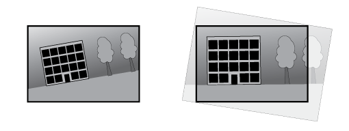 |
地平线矫正
地平线矫正可补偿摄像机的倾斜,否则会使其地平线弯曲。这提供了一个可感知并与地平线对齐的图像。 水平位置:使用滑块将黄色中心线移动到水平位置。您还可以直接在直播视图图像中移动中心线。 伸展:为了适合整个窗口,请打开以拉伸图像。 |
变焦同步
显示视觉与热成像通道之间的变焦同步功能是打开还是关闭。 |
交通摄像机安装协助
交通摄像机安装协助可根据您的具体安装环境,为您提供摄像机设置建议。
监控模式 选择监控模式,确定交通摄像机的主要目的:
捕捉设置 请提供以下信息,以便获得准确的摄像机设置建议:
安装概览 显示摄像机位置和角度的可视化呈现,指示显示是否需要调整。
图像设置 显示推荐的图像设置,以获得理想性能。选中复选框,应用推荐的设置。如需保留当前设置,请取消选中这些复选框。
应用设置:单击此项,用所选值更新摄像机设置。应用新设置后,请查看摄像机的方向,必要时进行调整。 |
融合对齐
融合透明度
Image order(图像顺序):选择在将热图像与可见光图像相结合时,哪种图像显示在最上方。 Image opacity(图像透明度):拖动滑块,或输入百分比,以调整顶层显示的透明度。 |
对齐融合视图
Fine tune alignment(微调对齐):使用箭头按钮将图像以微小幅度移动,直到它们对齐。 Factory reset(恢复出厂设置):将对齐方式恢复为出厂设置。 |
图像
呈现
场景配置文件:选择适合您的监控场景的场景配置文件。场景配置文件可优化特定环境或用途的图像设置,包括颜色级、亮度、锐度、对比度和局部对比度。
饱和度:使用滑块调整色彩浓度。例如,您可以获取一个灰度图像。  对比度:此滑块以调整明暗之间的差别。   亮度:使用滑块调整光线强度。这可使目标更易于查看。在捕捉图像后应用亮度,并不会影响图像的信息。要从黑暗区域获得更多详细信息,通常加大增益或增加曝光时间。   锐度:使用滑块通过调整边缘对比度以使图像中的目标显示得更锐利。如果增加锐度,可能会增加所需的比特率和存储空间量。   |
宽动态范围功能
WDR:打开以使图像的明暗区域均可视。 局部对比度:使用滑块调整图像对比度。较高的值会使亮度和光线区域之间的对比度更高。 色调映射:使用滑块以调整应用于图像的色调映射量。如果此值设置为零,仅应用标准灰度校正,而提高值将增加图像中更暗和更亮部分的可视性。 |
白平衡
如果摄像机侦测到接收的光线的色温,则可以调整图像,让颜色显得更自然。如果这还不够,您可从列表中选择合适的光源。
自动白平衡设置可通过逐渐适应变化来降低颜色闪烁的风险。若要更改照明或摄像机首次启动时,可能需要长达 30 秒来适应新光源。如果某个场景中存在多个类型的光源,即,这些光源的色温不同,则主导光源将用作自动白平衡算法的参考。通过选择与要用作参考的光源相匹配的固定白平衡设置,可以覆盖此行为。
光线环境:
|
日间-夜间模式
红外滤光片:
红外带通滤光片:打开后可阻挡可见光,仅允许近红外光通过。此切换按钮仅在红外滤光片设置为关闭时可用。 阈值:使用滑块调整摄像机从白天模式更改为夜间模式的光线阈值。
白天至夜间模式切换延时:设置延迟时间,以减少因光线短暂变化导致的白天模式至夜间模式的意外切换。例如,走廊里闪烁的灯光。 夜间至白天模式切换延时:设置延迟时间,以减少因光线短暂变化导致的夜间模式至白天模式的意外切换。例如,一辆驶过的汽车发出的灯光。 红外光 如果您的设备没有内置照明,则仅当连接支持的安讯士照明器时,这些控制才可用。 允许照明:打开此项,让摄像机在夜间模式下使用内置光线。 同步照明:打开可自动将照明与周围光线同步。日间/夜间同步仅在红外滤光片设置为自动或关闭时生效。 自动照明角度:打开以使用自动照明角度。关闭以手动设置照明角度。 照明角度:使用滑块手动设置照明角度,例如,如果角度需要不同于摄像机的视角。如果摄像机具有广阔视角,您可以将照明角度设置为较窄的视野(相当于更大的长焦位置)。这会导致图像有黑暗区域。 IR 波长:选择用于红外光线的所需波长。 白光 允许照明:打开以让摄像机在夜间模式下使用白色光。 同步照明:打开可自动将照明与白光同步。 |
曝光
选择曝光模式以减少图像中迅速变化的不良效应,如不同光源类型产生的闪烁。我们推荐您使用自动曝光模式,或使用与电力网络相同的频率。
曝光模式:
曝光区域:使用曝光区域优化场景选定部分的曝光,例如,入口门前面的区域。 注意 曝光区域与原始图像(不旋转)相关,且区域名称将应用于原始图像。这意味着,如果视频流旋转 90°,那么视频流中的上方区域将变为右,而左变为下方。
快门上限:选择快门速度以生成优化图像。低快门速度(曝光时间更长)可能导致运动时产生运动模糊,而过高的快门速度则可能影响图像质量。可以配合使用最大快门和最大增益来改善图像。 增益上限:选择合适的最大增益。如果增益上限加大,则会改善黑暗图像中细节的可视级别,但也会提高噪音级别。更多噪声还可能导致使用更多带宽和存储。如果将增益上限设置为较高值,且昼夜光线条件不同时,图像会差异很大。可以配合使用最大增益和最大快门以改善图像。 增益上限:选择合适的最大增益。如果增益上限加大,则会改善低对比度图像中细节的可视级别,但也会提高噪音等级。更多噪声还可能导致使用更多带宽和存储。 运动自适应曝光:选择以减少低照度条件下的运动模糊。 模糊-噪声平衡:使用滑块以调节运动模糊与噪声之间的优先级。如果您希望优先考虑低带宽,并以牺牲移动目标的细节来换取噪声降低,请将此参数调节为低噪音。如果您希望以牺牲噪声和带宽来优先保留移动目标的细节,请将此参数调节为低运动模糊。 注意 您可以通过调节曝光时间或调节增益来更改曝光。如果增加曝光时间,则会产生更多的运动模糊,并且如果增加增益,则会导致更多噪音。如果将模糊噪声平衡功能调整为低噪声,自动曝光将优先更长的曝光时间而不是增加增益,如果调整的平衡调整为低运动模糊,则相反。在低照度条件下,增益和曝光时间终会达到最大值,不论此参数如何设置优先级。 锁定光圈:打开以设置光圈滑块来保留光圈大小。关闭以让摄像机自动调整光圈大小。例如,您可以将光圈锁定在始终照亮的场景。 光圈:使用滑块来调整光圈大小,也就是说,镜头的进光量。要允许更多光线进入传感器,从而在低照度条件下生成较亮的图像,请移动滑块至打开。打开光圈也会降低景深,这意味着,离摄像机较近或较远的目标可能无法对焦显示。要使更多图像处于聚焦状态,请将滑块向关闭移动。 曝光级别:使用滑块调整图像曝光。 除雾:打开以侦测多雾天气的影响,并自动除雾以获得清晰的图像。 注意 我们建议您不要在低对比度、较大光线水平变体或自动对焦稍微熄灭的场景中打开除雾。这可能会影响图像质量,例如,在提高对比度时。另外,当除雾功能激活时,太多光量可能对图像质量产生负面影响。 |
过滤器
隐私过滤器可创建黑白视图,其外观平淡,旨在保护人和事的隐私。 铅笔:创建一个带有铅笔隐私过滤器的视图。 阈值:使用滑块或文本框为像素的亮度设置阈值。阈值下方的某些细节将被移除,这取决于场景的照明条件。 内核大小:使用滑块或文本框可在视图中设置内核的大小。更大的内核强调更大的边缘,而小型内核则强调较小的边缘。 |
光学器件
温度补偿:如果您希望根据光学器件中的温度来纠正对焦位置的调整,请打开。 红外线补偿:如果您希望在红外滤光片关闭和有红外线时对焦位置进行校正,请打开。 校准对焦和变焦:单击可将光学器件和变焦和对焦设置重置为出厂默认位置。如果光学器件在运输过程中失去了校准,或者设备已暴露于高振动,则需要执行此操作。 |
视频输入
视频端接:当设备与其他设备连接时关闭。如果您打开视频终结,可能会影响图像质量。我们建议您仅为视频信号链中的更后一个设备保持视频终端打开。 X 偏移:输入一个值,以水平调整图像的方向。 Y 偏移:输入一个值,以垂直调整图像的方向。 |
概述
名称:为选定摄像机输入一个名称。 |
拼接
不同的传感器图像拼接在一起,显示为一个完整的图像。 混合:滑块在不同传感器图像之间柔化线。 距离:滑块设置摄像机与场景中感兴趣的目标之间的距离(以米为单位)。在设置距离处,您可获得图像的优化拼接。 |
流
概述
分辨率:选择适合监控场景的图像分辨率。更高的分辨率会增加带宽和存储。 色板:选择一个调色板,以使用不同颜色为图像着色,具体取决于温度。该调色板可提高精细细节的可视性。 帧率:为了避免网络带宽问题或降低存储容量,可将帧速限制为一个固定值。如果将帧速保留为零,则帧速将保持在当前条件下可能的帧速上限。更高的帧速要求更多带宽和存储容量。 P 帧:P 帧是仅显示图像与前一帧的变化的预测图像。输入所需的 P 帧数量。该数量越高,所需带宽越少。但是,如果出现网络拥塞,视频质量可能会明显下降。 压缩:使用滑块调整图像压缩。高压缩导致更低的比特率和更差的图像质量。低级别的压缩可提高图像质量,但在录制时会使用更多带宽和存储。 签名视频:打开以将签名视频功能添加到视频。签名视频通过向视频添加加密签名来保护视频免受篡改。 |
Zipstream
Zipstream 是一种针对视频监控进行了优化的比特率降低技术,能够实时降低 H.264、H.265 或 AV1 流中的平均比特率。Axis Zipstream 在具有多个关注区域的场景(例如,有移动目标的场景)中应用高比特率。当场景更加静态时,Zipstream 使用更低的比特率,从而减少所需存储。要了解更多信息,请参见以 Axis Zipstream 降低比特率
优化存储:打开以在保持质量的同时尽可能降低比特率。优化不应用于网络客户端中显示的流。仅当您的 VMS 支持 B 帧时,才可使用此选项。打开优化存储还会打开动态 GOP。 动态 FPS (每秒帧数):打开以允许带宽因场景中的活动级别而异。更多的活动需要更多带宽。
动态图片组 (GOP) (图片组):打开以根据场景中的活动级别动态调整 I 帧之间的间隔。
|
比特率控制
|
方向
镜像:打开以镜像图像。 |
无损变焦
|
音频
包含:打开以在视频流中使用音频。 来源:选择要使用的音频源。 立体声:打开以包括内置音频以及来自外部麦克风的音频。 |
叠加
:单击以添加叠加。从下拉列表中选择叠加类型:
小部件:计量器:显示近期测量的数据值的条形图。
微件:速度可视化工具(雷达数据):显示一个文本叠加层,其中包含与场景交互的雷达轨迹的实时信息,例如当进入或离开一个区域。
|
视点区域
:单击以创建视点区域。 单击查看区域以访问设置。 名称:输入浏览区域的名称。上限长度可达 64 个字符。 PTZ:打开以使用视点区域中的水平转动、垂直转动和变焦功能。 |
隐私遮罩
:单击以创建新的隐私遮罩。 Privacy masks x/32(隐私遮罩 x/32)或 Privacy masks x/100(隐私遮罩 x/100):单击此标题栏可更改全部隐私遮罩的颜色,或永久删除全部隐私遮罩。 单元格大小:如果选择马赛克颜色,隐私遮罩将显示为像素化模式。使用滑块可更改像素的大小。 Mask x(遮罩 x):单击单个遮罩名称/编号可重命名、禁用或永久删除该遮罩。 Use zoom level(使用变焦级别):打开此项可使隐私遮罩仅在达到创建时的变焦级别时显示。缩小图像会再次隐藏遮罩。 |
画中画
:单击可创建新的画中画。 可见性:打开可在实时画面中显示画中画。 分辨率:选择画中画的尺寸。小、中或大。 透明度:使用滑块调节透明度。 注意 单击并拖动图像,即可在实时画面中移动图像。 |
空气质量监测器
仪表板
实时传感器数据
显示实时传感器数据。
- 设备首次运行时,达到设置的 CO2 检测精度需要 2 天时间。
- 空气质量指数 (AQI) 在设备上首次运行时,需要 12 小时才能正常工作。AQI 在获得足够数据之前将显示 Calculating(正在计算)。每次设备重启时都需要校准时间。
- 设备运行一小时后,即可获得完全的 VOC 精确度。每次设备重启时都需要校准时间。
- 设备运行6个小时后,即可获得完全的 NOx 精确度。每次设备重启时都需要校准时间。
:单击设置仪表板名称。 编辑:单击可显示或隐藏数据。 :单击可向仪表板添加数据。 单击可从仪表板删除数据。 温度:查看空气质量传感器的实时温度。 湿度:查看空气质量传感器的实时湿度。 CO2:查看实时二氧化碳浓度。
NOx:查看实时一氧化氮和二氧化氮浓度。
PM 1.0:查看实时颗粒物 1.0 浓度。 PM 2.5:查看实时颗粒物 2.5 浓度。
PM 4.0:查看实时颗粒物 4.0 浓度。 PM 10.0:查看实时颗粒物 10.0 浓度。
电子烟/吸烟:查看是否检测到电子烟或吸烟行为。
VOC:查看挥发性有机化合物指数。
AQI:查看空气质量指数。
湿度指数:查看来自空气质量传感器的实时湿度指数。
热指数:查看来自空气质量传感器的实时热指数。
|
设置
阈值
设置空气质量传感器数据。
温度:在 -10 至 45 范围内,设置温度 Min(最小值)和 Max(最大值)。 湿度:在 0 至 100 的范围内,设置湿度 Min(最小值)和 Max(最大值)。 CO2:在 0 至 40000 的范围内,设置二氧化碳 Min(最小值)和 Max(最大值)。 NOx:在 0 至 500 的范围内,设置一氧化氮和二氧化氮 Min(最小值) 和 Max(最大值)。 PM1.0:在 0 至 1000 的范围内,设置颗粒物 1.0 Min(最小值)和 Max(最大值)。 PM2.5:在 0 至 1000 的范围内,设置颗粒物 2.5 Min(最小值)和 Max(最大值)。 PM4.0:在 0 至 1000 的范围内,设置颗粒物 4.0 Min(最小值)和 Max(最大值)。 PM10.0:在 0 至 1000 的范围内,设置颗粒物 10.0 Min(最小值)和 Max(最大值)。 VOC:在 0 至 500 的范围内,设置挥发性有机化合物指数 Min(最小值)和 Max(最大值)。 AQI:在 0 至 500 范围内,设置空气质量指数 Min(最小值)和 Max(最大值)。 热指数:在 0 至 153 范围内,设置热指数 Min(最小值)和 Max(最大值)。 湿度指数:在 0 至 96 范围内,设置湿度指数 Min(最小值)和 Max(最大值)。 |
温度单元
Show temperature in(温度显示单位):Celsius(摄氏度)或 Fahrenheit(华氏度) |
电子烟烟雾侦测灵敏度
设置电子烟检测灵敏度。
| Low sensitivity(低灵敏度)与 High sensitivity(高灵敏度):使用滑块在低灵敏度与高灵敏度之间调整设备触发报警的差异。高灵敏度意味着设备能监测/侦测到微量吸烟或电子烟烟雾,触发报警的可能性更高;低灵敏度则表示设备仅对较大量吸烟或电子烟烟雾作出反应,从而降低假警报概率。 |
Storage setting(存储设置)
更改设备的存储设置:
转到 Air quality monitor(空气质量监测器) > Settings(设置)。
导航至 Storage settings(存储设置)。
从可用选项中选择首选存储选项。
更改存储选项将清除现有数据。
可变元数据
可变元数据功能适用于第三方平台,这些平台希望订阅具有可调传输频率的传感器元数据。可变元数据包含仪表板上显示的所有传感器数据。
可变元数据:开启以使用可变元数据。 注意 默认情况下此功能处于禁用状态;不会发送该主题的元数据。启用后,该主题的元数据将在下方设置的频率范围内传输。 Set frequency range(设置频率范围)(00:00:01 - 23:59:59):输入值以设定频率范围。 |
验证周期
您可以为以下空气质量设置设置验证周期。验证周期作为时间阈值,读数必须持续高于验证周期范围的上限才能触发报警。
示例
若二氧化碳验证周期为5秒,则二氧化碳浓度必须在整个5秒内持续高于上限才能触发报警。
为以下数据设置验证周期范围(0秒至60秒):
|
Modbus
Modbus 默认处于禁用状态。启用此选项后,您可以使用 Modbus 从空气质量传感器发送数据。
启用 Modbus 功能可能导致系统存在安全隐患。
Modbus TCP 寄存器
| 寄存器地址 | 名称 | 比例 | 单位 | 备注 |
| 0 | 温度 | 0.1 | oC | 0x00FF (225) –> 25.5 oC |
| 1 | 湿度 | 0.1 | %RH | 0x00FF (225) –> 25.5 %RH |
| 2 | CO2 | 1 | ppm | 0x01F4 (500) –> 500 ppm |
| 3 | VOC | 1 | - - | 0x0064 (100) –> 100 |
| 4 | NOX | 1 | - - | 0x0002 (2) –> 2 |
| 5 | AQI | 1 | - - | 0x0001 (1) –> 1 |
| 6 | 电子烟 | 1 | - - | 0x0001 (1) –> 1 |
| 7 | PM1.0 | 0.1 | μg/m3 | 0x0019 (25) –> 2.5 μg/m3 |
| 8 | PM2.5 | 0.1 | μg/m3 | 0x0019 (25) –> 2.5 μg/m3 |
| 9 | PM4.0 | 0.1 | μg/m3 | 0x0019 (25) –> 2.5 μg/m3 |
| 10 | PM10.0 | 0.1 | μg/m3 | 0x0019 (25) –> 2.5 μg/m3 |
| 11 | 湿度指数 | 1 | oC | 0x0019 (25) –> 25 oC |
| 12 | 热指数 | 1 | oC | 0x0019 (25) –> 25 oC |
统计数据
传感器数据统计
您最多可将365天的传感器统计数据导出为CSV文件,从而在Microsoft® Excel等应用程序中使用。
Predefined date range(预定义日期范围):从列表中选择您想要下载的预定义日期范围。
From(自)和To(至):请选择您希望下载的自定义范围。您可以下载为期达 365 天的数据。
- 注意
如果同时选择自定义范围和预定义范围,则自定义范围优先。
- 注意
最大下载范围受限于在Storage setting(存储设置)中配置的保留时间。
Select a source(选择数据源):选择您想要下载的数据源。
Download data(下载数据):从下拉菜单中选择Download selected sensor data(下载所选传感器数据)。
Download data for all sources(下载所有数据源的数据):导出所选时间段内所有数据源的数据。
- 文件将下载到您的下载文件夹中。下载可能需要一段时间,具体取决于文件大小。
通讯
VMS 呼叫
VMS 呼叫
Allow calls in the video management software (VMS)(允许在视频管理软件 (VMS) 中呼叫):选择以允许从设备呼叫VMS。即使关闭SIP,您也可以进行VMS呼叫。 呼叫超时:设置无人应答时尝试呼叫的持续时间上限。 |
联系人名单
接受者
设备
|
联系人
对于对讲机设备:
单击可将联系人列表下载为 json 文件。 单击导入联系人列表(json)。 Add contact(添加联系人):单击此处,将新联系人添加到联系人列表中。 上传图像:单击上传代表联系人的图像。 名字:输入联系人的名字。 姓氏:输入联系人的姓氏。 快速拨号:输入联系人的可用快速拨号号码。此号码用于从设备呼叫联系人。 SIP 地址:若您使用 SIP,请输入联系人的 IP 地址或分机号。 :单击以进行测试呼叫。当应答时,呼叫将自动结束。 SIP 账户:若您使用 SIP,选择要用于从设备呼叫联系人的 SIP 账户。 可用性:选择联系人的可用性时间表。您可以在系统 > 事件 > 时间表 中添加或调整时间表。如果在联系人不可用时尝试呼叫,呼叫将被取消,除非有备用联系人。 备用:如果适用,请从列表中选择一个备用联系人。 备注:添加有关联系人的可选信息。 上下文菜单包括: 编辑联系人:编辑联系人的属性。 删除联系人:删除联系人。 |
对于 AXIS C6110 Paging Console:
|
分组
对于对讲机设备:
单击可将联系人列表下载为 json 文件。 单击导入联系人列表(json)。 Add group(添加组):单击以创建新的现有联系人组。 上传图像:单击上传代表组的图像。 名称:为该组输入一个名称。 仅用于组呼叫:如果您想仅将组用于组呼叫则打开。如果要在组中添加单个联系人,但不使用该组进行组呼叫,请关闭。 快速拨号:输入组的可用快速拨号号码此号码用于从设备呼叫组。仅适用于组呼叫组。 接受者:选择要包括在组中的联系人。呼叫将同时发送给大多数接收者。接受者数量上限为 6。 备用:如果适用,请从列表中选择一个备用联系人。仅适用于组呼叫组。 备注:添加有关组的可选信息。 上下文菜单包括: 编辑组:编辑组的属性。 删除组:删除组。 |
对于 AXIS C6110 Paging Console:
用于使用 VAPIX 对一组安讯士设备进行寻呼。
Add group(添加组):单击以创建新的现有接受者。
|
呼叫
呼叫按钮
使用呼叫按钮:打开以使用呼叫按钮。 呼叫期间的按钮功能:选择从设备开始呼叫后呼叫按钮的功能。
备用光:在呼叫按钮周围为内置光选择一个选项。
接受者:选择或创建一个或多个要呼叫的联系人,以便在某人按下呼叫按钮时进行呼叫。如果您添加多个接收者,则呼叫将同时对各接收者进行。SIP 呼叫接收者数量上限为 6,而 VM 呼叫接收者数量不限。 备用:如果没有接收者回复,则从列表中添加备用联系人。 |
概述
音频 注意
铃声:选择要在有人呼叫设备时播放的音频剪辑。使用滑块调整增益。 回铃音:选择要在有人从设备呼叫时播放的音频剪辑。使用滑块调整增益。 |
显示
配置
主页
上下文菜单包括:
|
按钮
单击按钮以进行配置。
|
行动
|
显示设置
显示
|
显示锁定
显示锁定
|
本地化
显示语言
|
页面
添加:为显示屏创建新页面。 名称:为页面命名,帮助您识别此页面。 Background image(背景图像):从媒体库中选择一张图像作为背景。理想图像分辨率为 480x800 像素。允许的最大图像分辨率为 2048x2048 像素。 添加:在页面上添加小部件,如按钮、文本或图像。小部件是一种图形元素。
图像
图像:从媒体库中选择一张图像。允许的最大图像分辨率为 2048x2048 像素。 文本
上下文菜单包括: 编辑:调整页面。 重置:撤销页面上未保存的更改。 Duplicate(复制):创建页面副本。 Set as default homepage(设为默认主页):使该页面在无预定页面激活时显示。必须先保存页面,才能将其设置为主页。 时间表:选择此项,可按照 System(系统)> Events(事件)> Schedules(时间表)中定义的时间表之一显示页面。 删除:删除页面。无法删除设置为默认主页的页面。 |
时钟
预览
预览显示当前设置下的显示效果。
呈现
使用 24 小时制时钟:开启可显示 24 小时制时钟,如 14:30;关闭则显示 12 小时制时钟,如下午 2:30。 显示秒数:开启可同时显示小时、分钟和秒。关闭后只显示小时和分钟。 显示日期:开启以显示日期,关闭后隐藏日期。 字体颜色:设置显示屏上显示文字的颜色。 背景颜色:设置显示背景的颜色。 |
可用性
关闭:选择隐藏时钟。由规则触发的消息仍会出现在显示屏上。 始终开启:选择显示屏始终保持开启状态。 检测到存在时开启显示屏:选择当检测到存在时激活显示屏。如果在选定的待机时间内没有检测到存在,显示屏将关闭。 根据时间表开启显示屏:选择按照时间表激活显示屏。 反转时间表:选择可反转时间表。例如,如果您将一个事件安排在 8.00 - 12.00 之间播放,然后反转时间表,则该事件将改为在 12.00 - 8.00 之间播放。 |
概述
Device language(设备语言):选择显示屏默认文本的语言。 Show keypad on homepage(在主页上显示小键盘):打开可在默认主页上显示小键盘按钮。来访者可以按下该按钮打开小键盘,然后使用自己的凭证开门。 |
屏幕保护程序
添加:单击以创建新屏幕保护程序。屏幕保护程序可以是网页或图片。 持续时间:选择屏幕保护程序的显示时长。 编辑:从列表中选择屏幕保护程序,然后单击进行调整。 删除:从列表中选择一个或多个屏幕保护程序,然后单击将其删除。 设置:单击可调整通用屏幕保护程序设置。 Start screensaver when inactive(处于非活动状态达到以下时长时启动屏幕保护程序):设置屏幕保护程序启动前允许的非活动状态时长。如果设置的时间长于 Turn off display when inactive(处于非活动状态达到以下时长时关闭显示)中设置的时间,则屏幕保护程序将永远不会启动。 Turn off display when inactive(处于非活动状态达到以下时长时关闭显示):设置显示屏关闭前允许的非活动状态时长。该时长包含屏幕保护程序的显示时长。 Screensaver sequence(屏幕保护程序序列):如果屏幕保护程序不止一个,选择显示顺序。在切换到下一个屏幕保护程序之前,每个屏幕保护程序的显示时长为 Duration(持续时间)中所设置的时长。如果只有一个屏幕保护程序,它将反复显示。
Wake-up trigger(唤醒触发器):选择在屏幕保护程序激活或显示屏关闭时如何唤醒显示屏。
|
分析
AXIS Object Analytics
开始:单击以开始 AXIS Object Analytics。应用将在后台运行,您可以根据应用的当前设置为事件创建规则。 打开:单击以打开 AXIS Object Analytics。应用程序将在新的浏览器标签页中打开,您可以在其中配置其设置。 未安装:AXIS Object Analytics 未在此设备上安装。将 AXIS OS 升级到新版本以获取新版本的应用。 |
自动追踪
设置
这些设置适用于大多数追踪配置文件。您可以在每个配置文件中覆盖部分设置。
激活:打开以开始追踪,这通过已启用的配置文件自动进行,或通过单击图像中的目标手动完成。 视频目标:打开可在摄像机已确认的目标周围显示边界框。打开后,您还可以单击某个目标开始对其进行追踪。 虚拟区域和线:打开以显示包含区域、排除区域和虚拟线。 最大追踪时间:设置摄像机追踪一个目标的最大时间。关闭可无限期追踪目标。 超时:设置摄像机在失去追踪目标后,应等待返回初始位的时间。如果配置文件中设置了超时,则其将覆盖此处的超时。 |
与雷达配对时的设置: 激活:打开以开始追踪,这通过已启用的配置文件自动进行,或通过单击图像中的目标手动完成。 目标类型验证:适用于需要摄像机确认雷达分类结果,以便跟踪目标并触发关联事件的跟踪配置文件。在验证时间中设置摄像机进行验证所需的时间。 多目标行为:当多个目标同时满足某个配置文件的追踪条件时,或当不同目标同时触发多个具有相同优先级的配置文件时,控制摄像机的追踪行为。
视觉确认:在已确认目标上显示叠加层。
仅在自动追踪期间使用照明:打开可仅在雷达侦测到目标时使用红外光以节省电量。打开此功能后,系统将在以下路径自动创建同名规则:事件 > 规则。 |
追踪配置文件
+ 创建:单击以创建新的追踪配置文件。 AXIS Object Analytics 场景:选择您想要用于触发自动追踪的场景并开始操作。一个场景仅可用于一个追踪配置文件。在此场景中,侦测必须限制在预置位之一。 追踪配置文件名称:配置文件名称将基于场景名称生成,但您也可根据需要更新。 超时:设置摄像机在失去追踪目标后,应等待返回初始位的时间。该设置将覆盖“设置”页面中的超时设置。 使用配置文件:打开以启用配置文件。 |
与雷达配对时的设置: + 创建:单击以创建新的追踪配置文件。 雷达场景:选择您想要用于触发自动追踪的场景并开始操作。一个场景仅可用于一个追踪配置文件。 追踪配置文件名称:配置文件名称将基于场景名称生成,但您也可根据需要更新。
目标类型验证:打开可跟踪和触发事件,仅针对同时被雷达和摄像机分类识别的目标。 优先级:设置追踪配置文件的优先级。在多个配置文件中同时侦测目标时,将使用优先级。 |
AXIS Image Health Analytics
开始:单击以启动 AXIS Image Health Analytics。应用将在后台运行,您可以根据应用的当前设置为事件创建规则。 打开:单击以启动 AXIS Image Health Analytics。应用程序将在新的浏览器标签页中打开,您可以在其中配置其设置。 未安装:AXIS Image Health Analytics未在此设备上安装。将 AXIS OS 升级到新版本以获取新版本的应用。 |
AXIS Audio Analytics
音频分析:打开以允许音频分析。
声压级
Show threshold and events in graph(在图表中显示阈值和事件):打开此功能,可在侦测到声音尖峰时在图表中进行显示。 阈值:调整侦测阈值。应用程序将为超出阈值范围的声音记录音频事件。 |
自适应音频侦测
Show events in graph(在图表中显示事件):打开此功能,可在侦测到声音尖峰时在图表中进行显示。 阈值:移动滑块以调整检测阈值。下限阈值会将声音中的轻微尖峰记录为检测,而上限阈值只会将声音的显著尖峰记录为检测。 测试警报:单击测试以触发用于测试目的的检测事件。 |
音频分类
Show events in graph(在图表中显示事件):打开此功能,可在侦测到特定类型的声音时在图表中进行显示。 Classifications(分类):选择希望应用程序侦测的声音类型。 测试警报:单击 Test(测试),以触发对特定声音的侦测事件,供测试之用。 |
定向音频侦测:打开,帮助识别声音的方向。
触发级别
Audio pointer(音频指针):打开以查看声音来源。 阈值:移动滑块,调整检测到的音频的阈值。高于设置的阀值(高于背景噪音)的声音会被检测为潜在的音频事件。 持续时间:设置在侦测到第一个音频事件后忽略其他音频事件的时间间隔。 |
音频侦测多视图
视点区域超时:设置在多长时间后将某个事件视为过期。 |
音频事件日志
实时更新日志:打开,显示实时音频事件信息。 |
PTZ
设置默认垂直转动:手动调整 PTZ 摄像机的垂直转动后,单击。当音频侦测找不到任何垂直转动信息时,就使用默认垂直转动值。 PTZ 移动:打开,使 PTZ 摄像机朝声音方向移动。 |
AXIS Live Privacy Shield
开始:单击启动 AXIS Live Privacy Shield。该应用程序可让您远程监视活动,同时保护隐私。 打开:单击打开 AXIS Live Privacy Shield。应用程序将在新的浏览器标签页中打开,您可以在其中配置其设置。 未安装:此设备未安装 AXIS Live Privacy Shield。将 AXIS OS 升级到新版本以获取新版本的应用。 |
元数据可视化
摄像机可侦测移动目标,并根据目标类型对其进行分类。在视图中,已分类目标周围有一个彩色边界框以及为其分配的 ID。 ID(标识号):已识别目标和类型的唯一标识号。此数字同时显示在列表和视图中。 类型:将移动目标分类为人、人脸、汽车、公共汽车、卡车、自行车或牌照。边界框的颜色取决于类型分类。 置信度:该条形表示目标类型分类的置信度。 |
元数据配置
实时流协议 (RTSP) 元数据生成器
查看和管理传输元数据的通道及其使用的协议。
这些设置适用于使用 ONVIF XML 的 RTSP 元数据流。此处更改的设置不会影响元数据可视化页面。
生成器:使用实时流协议 (RTSP) 传输元数据的通道。 通道:用于从生成器发送元数据的通道。启用此选项可开启元数据流。出于兼容性或资源管理原因,可以禁用此选项。 |
MQTT
配置将通过 MQTT(消息队列遥测传输)生成和传输元数据的生成器。
保留消息:选择是否保留 MQTT 主题中的最后一条消息。 使用 MQTT 客户端设备主题前缀:选择是否为 MQTT 主题添加前缀,以便识别源设备。 上下文菜单包括:
|
目标抓拍:启用此功能可添加对每个监测到的目标的裁剪图像。 附加裁剪边界:启用此功能可在监测到的目标图像周围添加额外的边界。 |
温度测量
测温技术
色板
色板中的颜色突出了色温差异。 名称以Iso开头的调色板是等温色板。等温色板可以将特定的色彩隔离到特定的色温等级。 低级别表示调色板彩色部分的开始位置。如果选择等温调色板,图像中的垂直条将显示用户定义的温度水平。
色板:选择调色板为图像上色并提高精细细节的可见性。 高级别:键入高级别温度范围开始的温度。竖条表示高级别温度的颜色。 中级别:键入中级别温度范围开始的温度。竖条表示中级别温度的颜色。 低级别:键入低级别温度范围开始的温度。竖条表示低级别温度的颜色。 Min level(最低级别):键入最低级别温度范围开始的温度。竖条表示最低级别温度的颜色。 显示调色板:选择以在图像中将调色板的颜色比例显示为垂直条。 |
点测
测量点温度:打开后,可以单击图像中的位置来测量和显示该点的温度。 |
温度单元
选择以摄氏度或华氏度显示温度。 |
温度侦测
通过温度侦测,您可以在场景中定义多达十个区域,以监控温度。创建规则时,您可以在系统 > 事件中,使用侦测区域作为条件。
温度侦测:单击可永久删除各侦测区域。 预置位:选择一个预设位置,以创建、更新或删除温度侦测区域。 报警时暂停防护活动:打开以在触发警报时暂停防护导向。 报警后恢复防护:当不再满足警报条件时,请打开以继续播放轮巡。 Add detection area(添加侦测区域):单击以创建新的侦测区域。在创建或编辑侦测区域之前关闭轮巡。 名称:键入侦测区域的描述性名称。 使用区域:启用该选项可以在创建规则时使用侦测区域及其设置。 侦测条件:设置侦测高温或低温或温度变化的条件。
包括温度:选择以在视频流中显示温度。 |
偏差检测
通过偏差检测,您可以监控两个或多个区域之间的温差是否变得太大。这些区域是使用在温度检测下创建的叠加来定义的。在系统 > 事件中,您可以使用温度偏离作为创建规则的条件。
Add deviation group(添加偏差组):单击以创建新的偏差组。 组名:为该组输入一个名称。 使用组:启用此选项可在创建规则时使用偏差检测。 添加要分组的区域:选择要分组的区域。 要比较的区域温度:选择比较方法:
偏差上限:输入温度和时间延迟的偏差限值。 包含:打开以在触发警报时显示叠加层。 |
雷达
设置
概述
无线电传输:用于完全关闭雷达模块。 通道:如果您遇到多个设备相互干扰的问题,请为最多四个彼此靠近的设备选择同一信道。对于大多数装置,选择自动让设备自动协商使用哪个信道。 安装高度:输入产品的安装高度。 注意 输入安装高度时尽可能具体。这有助于设备在图像中的正确位置可视化雷达侦测。 |
共存
邻近雷达的数量:选择在同一个共存区域内安装的邻近雷达的数量。这有助于避免干扰。共存半径为 350 米(1,148 英尺)。
|
侦测
侦测灵敏度:选择雷达的灵敏程度。值越高,侦测范围就越长,但出现假警报的风险也越高。较低的灵敏度将消除假警报的数量,但可能会缩短侦测范围。
忽略小型目标:打开以尽可能减少来自小型目标(如猫或兔子)的假警报。 忽略静止的旋转对象:打开此选项可尽可能地减少具有旋转运动的静止目标(如风扇或涡轮机)发出的误报。 忽略摆动的目标:打开以尽量减少摆动的目标(如树木、灌木丛或旗杆)发出的假警报。 忽略未知目标:打开此功能可最大限度减少因雷达无法分类的目标引发的假警报。 |
交通助手
状态: 显示配置状态。 配置:单击可打开设置助手,引导您逐步完成校准。 |
查看
信息说明:打开以显示包含雷达可侦测和追踪的目标类型的图例。拖放可移动信息图例。 区域透明度:选择覆盖区域应有的不透明或透明程度。 网格透明度:选择网格应有的不透明或透明程度。 颜色方案:为雷达可视化选择一个主题。 旋转:选择雷达图像的首选方向。 |
目标可视化
轨迹寿命:选择所追踪的目标的轨迹在雷达视图中可见的时间。 图标风格:在雷达视图中选择所追踪目标的图标样式。对于普通三角形,请选择 三角形 。对于代表符号,请选择符号。无论采用哪种样式,这些图标都将指向所追踪目标移动的方向。
|
流
概述
分辨率:选择适合监控场景的图像分辨率。更高的分辨率会增加带宽和存储。 色板:选择一个调色板,以使用不同颜色为图像着色,具体取决于温度。该调色板可提高精细细节的可视性。 帧率:为了避免网络带宽问题或降低存储容量,可将帧速限制为一个固定值。如果将帧速保留为零,则帧速将保持在当前条件下可能的帧速上限。更高的帧速要求更多带宽和存储容量。 P 帧:P 帧是仅显示图像与前一帧的变化的预测图像。输入所需的 P 帧数量。该数量越高,所需带宽越少。但是,如果出现网络拥塞,视频质量可能会明显下降。 压缩:使用滑块调整图像压缩。高压缩导致更低的比特率和更差的图像质量。低级别的压缩可提高图像质量,但在录制时会使用更多带宽和存储。 签名视频:打开以将签名视频功能添加到视频。签名视频通过向视频添加加密签名来保护视频免受篡改。 |
Zipstream
Zipstream 是一种针对视频监控进行了优化的比特率降低技术,能够实时降低 H.264、H.265 或 AV1 流中的平均比特率。Axis Zipstream 在具有多个关注区域的场景(例如,有移动目标的场景)中应用高比特率。当场景更加静态时,Zipstream 使用更低的比特率,从而减少所需存储。要了解更多信息,请参见以 Axis Zipstream 降低比特率
优化存储:打开以在保持质量的同时尽可能降低比特率。优化不应用于网络客户端中显示的流。仅当您的 VMS 支持 B 帧时,才可使用此选项。打开优化存储还会打开动态 GOP。 动态 FPS (每秒帧数):打开以允许带宽因场景中的活动级别而异。更多的活动需要更多带宽。
动态图片组 (GOP) (图片组):打开以根据场景中的活动级别动态调整 I 帧之间的间隔。
|
比特率控制
|
音频
包含:打开以在视频流中使用音频。 来源:选择要使用的音频源。 立体声:打开以包括内置音频以及来自外部麦克风的音频。 |
地图校准
使用地图校准上传和校准参考地图。校准的结果是一张参考地图,以适当的比例显示雷达覆盖范围,从而更容易看清目标移动的位置。
设置助手:单击可打开设置助手,引导您逐步完成校准。 重置校准:单击可删除当前地图图像和雷达在地图上的位置。 |
地图
上传地图:选择或拖放要上传的地图图像。 下载地图:单击可下载地图。 Rotate map(旋转地图):使用滑块来旋转地图图像。 |
地图上的比例尺和距离
距离:添加您添加到地图上的两点之间的距离。 |
水平转动和变焦缩放地图
水平转动:单击按钮可水平转动地图图像。 变焦:单击按钮可变焦缩放地图图像。 重置水平转动和变焦缩放:单击可移除水平转动和变焦缩放设置。 |
雷达位置
位置:单击按钮在地图上移动雷达。 旋转:单击按钮在地图上旋转雷达。 |
车道
车道可提高雷达的性能以及在监控道路上的车道时跟踪车辆的能力。在雷达中为您监控的每个实际车道添加一个车道。 Add lane(添加车道):单击以添加新车道。使用鼠标修改已添加的车道的形状。 :单击以展开并编辑车道名称。 :单击以删除该车道。 已启用通道:打开以激活已添加的车道。 |
排除区域
排除区域是一个忽略移动目标的区域。如果场景内存在触发大量不必要的警报的区域,请使用排除区域。 :单击以创建新的排除区域。 要修改排除区域,请在列表中选择它。 追踪正在通过的目标:打开以追踪穿过排除区域的目标。经过的目标会保留其轨迹 ID,并且在整个区域中可见。将不会追踪从排除区域内显示的目标。 区域形状预设:选择排除区域的初始形状。
|
场景
场景是触发条件以及场景和检测设置的组合。 :单击以创建新方案。您可以创建多达 20 个场景。
对于越线:
|
叠加
:单击以添加叠加。从下拉列表中选择叠加类型:
小部件:计量器:显示近期测量的数据值的条形图。
微件:速度可视化工具(雷达数据):显示一个文本叠加层,其中包含与场景交互的雷达轨迹的实时信息,例如当进入或离开一个区域。
|
动态 LED 灯带
动态 LED 灯带模式
使用此页面测试动态 LED 灯带的模式。 模式:选择要测试的模式。 持续时间:指定测试持续时间。 测试:单击以启动要测试的模式。 停止:单击以停止测试。如果您在播放模式时离开页面,该模式将自动停止。 要激活用于指示或威慑目的的模式,请转到系统 > 事件,然后创建一个规则。有关示例,请参见 。 |
雷达 PTZ 自动追踪
将雷达与 PTZ 摄像机配对以使用雷达自动追踪。要建立连接,请转至系统 > 边缘到边缘。
配置初始设置: 摄像机安装高度:地面与 PTZ 摄像机安装高度之间的距离。 水平调整:平移 PTZ 摄像机,使其指向与雷达相同的方向。单击 PTZ 摄像机的 IP 地址以访问 PTZ 摄像机。 保存水平转动偏移:单击以保存平移对齐方式。 地面倾斜偏移:使用地面倾斜偏移来微调摄像机的倾斜度。如果地面是倾斜的,或者摄像机不是水平安装,摄像机在追踪目标时可能瞄准得太高或太低。 已完成:单击以保存您的设置并继续配置。 |
配置 PTZ 自动追踪: 追踪:选择是否要追踪人员、车辆和/或未知目标。 追踪:打开以开始使用 PTZ 摄像机追踪目标。追踪将自动聚焦一个或一组目标,以让它们保持在摄像机的画面中。 目标切换:如果雷达侦测器检测到有多个目标不适合 PTZ 摄像机的画面,PTZ 摄像机将追踪雷达给出上限优先级的目标,并忽略其他目标。 目标保持时间:确定 PTZ 摄像机追踪每个目标时应持续的时间。 返回到初始位:打开以在雷达不再追踪目标时可以让 PTZ 摄像机返回到其初始位置。 返回到初始位超时:确定 PTZ 摄像机在返回到初始位前应该停留在所追踪目标新近已知位置的持续时间。 变焦:使用滑块微调 PTZ 摄像机的变焦。 重新配置安装:单击以清除各设置并返回到初始配置。 |
自动校准
校准结束:当校准达到满意水平且您希望将其冻结时,请打开此选项。
高度
自动校准高度可改善雷达边界框的垂直放置。不会影响物体侦测,只会影响外观。
状态:显示是否存在校准数据,以及校准是否仍在进行中。除非您打开校准结束,否则摄像机和雷达会持续收集校准数据。 自动校准:打开以自动校准场景。一旦校准数据可用,就会自动校准。检查状态以了解可用性。
重置:重置自动校准和收集的校准数据。 显示高程模式:打开以可视化校准。以彩色圆点模式显示从地面到摄像机的垂直距离。该模式仅在此页面上可见,在视频或雷达流中不可见。 显示颜色图例:打开以显示包含高程图案的颜色和每种颜色表示的垂直距离的图例。该图例仅在此页面上可见,在视频或雷达流中不可见。 颜色:选择高程图案的颜色。 显示参考区域:打开以显示校准所基于的区域。该地区仅在此页面上可见,在视频或雷达流中不可见。 |
方位角
自动校准方位角可改善雷达边界框的水平放置。不会影响物体侦测,只会影响外观。
状态:显示是否存在校准数据,以及校准是否仍在进行中。除非您打开校准结束,否则摄像机和雷达会持续收集校准数据。 自动校准:打开以自动校准场景。一旦校准数据可用,就会自动校准。检查状态以了解可用性。 重置:重置自动校准和收集的校准数据。 |
PTZ
预置位
预置位是存储在摄像机内存中的特定水平转动、垂直转动和变焦位置。您可以使用预置位在不同视野之间快速导航。如果您的设备支持轮巡功能,则可以使用预置位创建自动轮巡。
预置位
设置
上下文菜单包括:
|
轮巡
轮巡:创建轮巡。
|
预设位
具有预设位置的轮巡通过随机或固定序列中的选择预设位置连续地流式传输片段。在移动到下一个预设位置时,您可以选择摄像机在各预设位置应停留多长时间。即使没有客户端(网页浏览器)流式传输该素材,轮巡仍将继续以无限循环的状态运行。
设置
预置位:要选择多个预设位,请在选择预设位置时按住 Shift键。单击并将预设位拖动到 View order(查看顺序)区域。 查看顺序:显示包含在轮巡导览中的预设位置。
|
已录制
轮巡录制重放一系列已录制水平转动/垂直转动/变焦动作,其中包括其可变速度和长度。
一般设置
已录制轮巡
|
限制
要缩小监控范围下的区域,您可以限制 PTZ 移动。 保存为水平转动0°:单击可将当前位置设置为水平转动坐标的零点。 水平转动-垂直转动限制:当您设置水平转动垂直转动限制时,摄像机将使用图像中心的坐标。
自动翻转:让摄像机头能够立即反转 360° 并继续水平转动超出其机械限制。 垂直翻转 (E-flip) 功能:当摄像机垂直转动超过 -90° 时,通过将图像翻转 180° 自动校正摄像机视图。 最低点翻转:当垂直转动超过 -90° 时,让摄像机水平转动 180°,然后继续向上。 变焦限制:选择一个值以限制摄像机的上限变焦级别。光学或数字(例如 480x D)值均可选择。使用操纵杆时,仅可使用数字变焦级别来设置变焦值限制。 近距离对焦限制:选择一个值以防止摄像机对靠近摄像机的目标自动对焦。这样,摄像机可忽略架空电线、路灯或附近其他目标等目标。要让摄像机对焦于关注区域,请将近距离对焦限制设置为大于不关注目标显示距离的值。 |
运动
比例速度:打开以设置上限比例速度。
可调整变焦速度:使用操纵杆或鼠标滚轮控制变焦时,打开以使用可变速度。变焦速度可在 VAPIX® 应用程序编程接口 (API) 中通过命令 冻结 PTZ 上的图像
水平转动-垂直转动速度:选择摄像机的水平和垂直转动速度。 |
OSDI 区域
屏幕上的方向指示器 (OSDI) 以文字叠加方式提供摄像机所指方向的信息。当您设置左下方区域和右上方区域时,摄像机可使用图像中心的坐标。 创建OSDI区域:单击以创建 OSDI 区域。
上下文菜单包括:
|
定向辅助
方向辅助工具:打开以激活以正确的方向以及与摄像机移动同步的 2D 指南针叠加用户定义的关注点(包括视野)。 方向
Preset positions(预置位):选择用于方向辅助的预置位。
|
网守功能
门守用于监视入口等区域。在监视区域中侦测到移动时,门卫值守会将摄像机导向所选预置位置。使用放大的预置位可读取车牌或识别人员。当再也侦测不到移动时,摄像机将在定义的时间之后返回其初始位置。 |
控制队列
用户控制队列
设置
|
设置
Use PTZ(使用PTZ):打开以允许所选视图中的PTZ功能。 |
读卡器
连接
外部读卡器(输入)
使用外部 OSDP 读卡器:打开以将设备与外部读卡器配合使用。将读卡器连接至读卡器连接器(IO1、IO2、12V 和 GND)。
|
读卡器协议
读卡器协议类型:选择要用于读卡器功能的协议。
|
输出格式
选择数据格式:选择将卡数据发送到访问控制单元的格式。
设施代码覆盖模式:选择用于覆盖设施代码的选项。
|
芯片类型
芯片类型
激活芯片类型:从列表中选择一种芯片类型以将其激活。 活动芯片类型显示活动芯片类型列表及其是否使用默认或自定义数据集。 上下文菜单包括:
|
数据集
Invert byte order for all chip types using the full card serial number (CSN)(使用完整卡序列号 (CSN) 反转所有芯片类型的字节顺序):打开可反转卡序列号的字节顺序。卡序列号为默认数据。 使用安全卡数据反转全部芯片类型的字节顺序:打开以反转使用自定义数据集的芯片类型的安全卡数据的字节顺序。 添加数据集:选择芯片类型,然后单击添加数据集。用于自定义数据。
|
PIN
PIN 设置必须与在访问控制单元中配置的设置相匹配。
Length (0–32)(长度 (0-32)):输入PIN的位数。如果用户在使用读卡器时不需要使用PIN,请将长度设置为0。 Timeout (seconds, 3–50)(超时(秒,3-50)):输入在未收到PIN时设备返回到空闲模式之前需要的秒数。 |
入口列表
通过入口列表,您可以将设备设置为允许凭据持有者使用其卡、PIN 或一个二维码®执行不同的操作,例如开门。将凭证本地存储在设备中。您还可以将此功能与外部门禁控制器结合使用。
QR 码是 Denso Wave Incorporated 在日本和其他国家/地区的注册商标。
凭证持有者
使用入口列表:打开以使用入口列表功能。 使用已连接的门禁控制器:如果设备已连接到门禁控制器,请打开。如果有人提供的凭证在入口列表中不存在,我们会将请求发送到已连接的门禁控制器。我们不发送入口列表中可用的凭证。 添加凭证持有者:单击以添加新的凭证持有者。 名字:输入名字。 姓氏:输入姓氏。 凭证类型:
事件条件:选择凭证持有者使用其凭证时要触发的一个或多个条件。要设置生成的操作,请转到系统>事件 并使用您在此处选择的相同条件创建规则。 生效日期:选择当前设备时间以立即激活凭证。清除以指定何时激活凭证。 有效期至:
备注:输入可选信息。 暂停:选择此选项可使凭证暂时无效。 保存时下载二维码:如果您选择二维码作为凭证类型,请选择此复选框,以便在点击 Save(保存) 时下载二维码。 |
事件日志
事件登录显示一个入口列表事件的列表。登录文件的最大大小为 2 MB,约等于 6000 个事件。
导出全部:单击可导出列表中的所有事件。如要仅导出子集,请选择您感兴趣的事件。事件会导出到 CSV 文件中。 过滤器:单击可显示特定时间范围内发生的事件。 :键入可在列表中搜索所有匹配内容。 |
音频
AXIS Audio Manager Edge
AXIS Audio Manager Edge:启动应用程序。 |
音频场所安全
CA 证书:选择要向音频场所添加设备时使用的证书。您必须在 AXIS Audio Manager Edge 中启用 TLS 身份验证。 保存:激活并保存您的选择。 |
设备设置
输入:打开或关闭音频输入。显示输入类型。
允许流提取:开启以允许流提取。 输入类型:选择输入类型,例如,内部麦克风或线路输入。 麦克风:选择将用于音频输入的麦克风。 电源类型:选择用于输入的电源类型。 应用更改:应用您的选择。 降噪:打开以通过消除背景噪音来提高音频质量。 消除回音:打开以在双向通信期间移除回声。 单独的增益控制:打开以单独调整不同输入类型的增益。 自动增益控制:打开以动态调整声音中的变化增益。 增益:使用滑块更改增益。单击麦克风图标可静音或取消静音。 |
输出:显示输出类型。
增益:使用滑块更改增益。单击扬声器图标可静音或取消静音。 自动音量控制:打开可使设备根据周围噪音等级自动动态调节增益。自动音量控制会影响所有音频输出,包括线路输出和电传线圈输出。 |
音频输出 启用输出:打开或关闭音频输出连接器中的音频。 音频输出同步:设置一个时间以匹配音频输出(3.5 mm)端口和视频流之间的延迟差异。 |
流
编码:选择要用于输入源流传输的编码。只有打开了音频输入时,才能选择编码。如果音频输入已关闭,单击启用音频输入将其打开。 |
音频剪辑
添加片段:添加新的音频剪辑。您可以使用 au、. mp3、opus、vorbis、.wav 文件。 播放音频片段。 停止播放音频片段。 上下文菜单包括:
|
监听和录制
单击以进行侦听。 开始实时音频流的连续录制。再次单击可停止录制。如果正在进行录制,它将在重启后自动恢复。 注意 只有当设备的输入打开时,才能进行监听和录制。转到音频 > 设备设置,确保您已经打开输入。 显示设备的已配置存储。要配置存储,您需要以管理员身份登录。 |
音频增强
输入
十波段图形音频均衡器:打开此项可调整一个音频信号内不同频段的级别。此功能适用于具有音频配置体验的高级用户。 对讲范围:选择操作范围以收集音频内容。提升操作范围会降低同时双向的通信能力。 声音增强:打开以增强与其他声音相关的语音内容。 |
扬声器测试
您可以使用扬声器测试来远程验证扬声器按预期工作。 校准:首次测试前,您需要先校准扬声器。校准时,扬声器播放一系列由内置麦克风记录的测试音。校准扬声器时,要将其安装在其尾端。如果之后移动扬声器或者其环境发生改变,例如,新砌或拆除了墙壁,则应重新校准扬声器。 进行测试:播放校准期间播放的相同系列的测试音,并将其与校准的注册值进行比较。 |
源
设备
Add camera source(添加摄像机来源):单击以添加新摄像机来源。
手动:手动添加设备。
上下文菜单包括: 编辑:编辑视频源的属性。 删除:删除视频源。 |
媒体
添加:单击以添加新媒体源。
|
灯光
概述
灯光状态
显示设备上运行的不同灯光的活动。灯光列表中可以同时运行高达 10 个活动。当同时运行两个或更多个活动时,具有高优先级的活动将显示灯光状态。该行将在状态列表中以绿色突出显示。
LED 信号灯状态
显示在设备上运行的不同 LED 信号灯活动。LED 信号灯状态列表中可以同时运行高达十个活动。当同时运行两个或更多个活动时,具有较高优先级的活动显示 LED 信号灯状态。该行将在状态列表中突出显示。
警报声状态
显示在设备上运行的不同警报活动。警报声状态列表中可以同时运行高达十个活动。当同时运行两个或更多个活动时,将运行具有较高优先级的活动。该行将在状态列表中突出显示。
音频 LED 状态
显示设备上运行的不同音频 LED 的活动。音频 LED 状态列表中可以同时运行多达 10 个活动。当同时运行两个或更多个活动时,将运行具有较高优先级的活动。该行将在状态列表中以绿色突出显示。
音频扬声器状态
显示设备上运行的不同音频扬声器的活动。音频扬声器状态列表中可以同时运行多达 10 个活动。当同时运行两个或更多个活动时,将运行具有较高优先级的活动。该行将在状态列表中以绿色突出显示。
维护
维护模式:打开以在设备维护期间暂停灯光和警报活动。打开维护模式后,设备会显示一个三角形的白色脉动光图案,警报器也会静音。它可以保护安装人员免受听力损伤和耀眼强光的伤害。 维护优先级别为 11。只有具有更高优先级的系统特定活动才会中断维护模式。 维护模式重启后仍有效。例如,如果将时间设置为 2 小时,关闭设备并将其重新启动一小时后,设备将处于维护模式下又一个小时。 当您执行默认重置时,设备将返回到维护模式。 持续时间
|
运行状况检查
检查:检查设备的运行状况,以确保灯光和警报正常工作。其逐个打开每个灯光部分,并播放测试音频,以检查设备是否工作正常。如果无法通过运行状况检查,请转到系统日志以了解更多信息。 |
配置文件
配置文件
配置文件是一组配置的集合。您可以拥有多达 30 个具有不同优先级和模式的配置文件。配置文件列出,以提供名称、优先级、灯光和警报器设置的概览。
创建:单击以创建配置文件。
导入:添加一个或多个具有预定义配置的配置文件。
要复制配置文件并将其保存至其他设备,选择一个或多个配置文件,然后单击导出。导出一个 .json 文件。 启动配置文件。配置文件及其活动出现在状态列表中。 选择Edit(编辑)、Copy(复制)、Export(导出)或Delete(删除)配置文件。 |
录像
正在进行的录制内容:显示设备上全部正在进行的录制。 开始在设备上进行录制。 选择要保存到哪个存储设备。 停止在设备上进行录制。 触发的录制将在手动停止或设备关闭时结束。 连续录制将继续,直到手动停止。即使设备关闭,录制也会在设备再次启动时继续。 |
播放录制内容。 停止播放录制内容。 显示或隐藏有关录制内容的信息和选项。 设置导出范围:如果只想导出部分录制内容,输时间跨度。请注意,如果您工作的时区与设备所在地的时区不同,时间跨度将基于设备所在的时区。 加密:选择此选项可为导出的录制文件设置密码。如果没有密码,将无法打开导出的文件。 单击以删除一个录制内容。 导出:导出全部或部分录像。您可以导出为Matroska或MP4格式。 |
单击以过滤录制内容。 从:显示在某个时间点之后完成的录制内容。 到:显示在某个时间点之前的录制内容。 来源:显示基于源的录制内容。源是指传感器。 事件:显示基于事件的录制内容。 存储:显示基于存储类型的录制内容。 |
媒体
+ 添加:单击以添加新文件。 存储位置:选择将文件存储到内存或板载存储(SD 卡,如有)中。 上下文菜单包括:
|
应用
添加应用:安装新应用。 查找更多应用:查找更多要安装的应用。您将被带到 Axis 应用程序的概览页面。 允许未签名的应用:启用允许安装未签名的应用。 查看 AXIS OS 和 ACAP 应用程序中的安全更新。 注意 如果同时运行多个应用,设备的性能可能会受到影响。 使用应用名称旁边的开关可启动或停止应用。 打开:访问应用的设置。可用的设置取决于应用。某些应用程序没有任何设置。 上下文菜单可包含以下一个或多个选项:
|
系统
时间和位置
日期和时间
时间格式取决于网页浏览器的语言设置。
我们建议您将设备的日期和时间与 NTP 服务器同步。
同步:选择设备日期和时间同步选项。
时区:选择要使用的时区。时间将自动调整为夏令时和标准时间。
注意 系统在各录像、日志和系统设置中使用日期和时间设置。 时间同步状态:显示 NTP 同步信息和 PTP 状态。 网络时间同步捕获:打开此功能可允许多台摄像机同时捕捉图像。 |
设备位置
输入设备所在的位置。视频管理系统可以使用此信息来在地图上放置设备。
|
区域设置
设置要在全部系统使用的单位制。
Metric(公制)(m、km/h):选择米作为距离测量单位,公里/小时为速度测量单位。 U.S. customary(美国常用)(ft、mph):选择英尺为距离测量单位,英里/小时为速度测量单位。 |
WLAN
借助无线 USB 适配器,设备可连接到无线网络。
国家/地区:要提高驱动程序定位网络接入点的能力,请选择设备所在的国家/地区。 添加网络:添加不广播其 SSID(名称)的无线网络。输入 SSID 名称和用于无线网络的设置。请联系网络管理员以获得所需的设置。 Refresh(刷新):更新可用无线网络的列表。 上下文菜单包括:
|
配置检查
交互式设备图像:单击图像中的按钮模拟实际按键。这允许您尝试配置或排除硬件故障,而无需物理访问设备。 新凭据:显示有关上次注册的凭证的信息。 显示新的凭证数据。 上下文菜单包括:
检查凭证:输入 UID 或 PIN 并提交以检查凭证。系统的响应方式与您在设备上使用凭证的方式相同。如果同时需要 UID 和 PIN,请先输入 UID。 |
网络
IPv4
自动分配 IPv4:选择 IPv4 自动获取 IP 地址 (DHCP),即可由网络自动分配您的 IP 地址、子网掩码和路由器,无需手动配置。我们建议大多数网络采用自动 IP 分配 (DHCP)。 IP 地址:为设备输入唯一的 IP 地址。在独立的网络中可随机分配静态 IP 地址,只要每个指定地址是唯一的。为避免冲突,建议在分配静态 IP 地址前联系网络管理员。 子网掩码:输入子网掩码,以定义局域网内的地址。局域网之外的地址都通过路由器。 路由器:输入默认路由器(网关)的 IP 地址用于连接已连接至不同的网络和网段的设备。 如果 DHCP 不可用,退回到静态 IP 地址:如果希望在 DHCP 不可用且无法自动分配 IP 地址时,添加要用作备用静态 IP 地址,请选择此项。 注意 如果 DHCP 不可用且设备使用备用静态地址,则静态地址配置范围有限。 |
IPv6
自动分配 IPv6:选择打开 IPv6 并让网络路由器自动分配设备的 IP 地址。 |
主机名
自动分配主机名称:选择让网络路由器自动分配设备的主机名称。 主机名称:手动输入主机名称,作为访问设备的另一种方式。服务器报告和系统日志使用主机名。允许的字符是 A–Z, a–z, 0–9 和 -。 启动动态 DNS 更新: 允许设备在 IP 地址更改时自动更新其域名服务器记录。 注册 DNS 名称:输入指向设备 IP 地址的唯一域名。允许的字符是 A–Z, a–z, 0–9 和 -。 TTL:生存时间 (TTL) 设置 DNS 记录在需要更新之前保持有效的时长。 |
DNS 服务器
自动分配 (DNS):选择以让 DHCP 网络路由器自动向设备分配搜索域和 DNS 服务器地址。我们建议大多数网络采用自动 DNS(DHCP)。 搜索域:当您使用不完全合格的主机名时,请单击添加搜索域并输入一个域,以在其中搜索设备使用的主机名称。 DNS 服务器:单击添加 DNS 服务器并输入 DNS 服务器的 IP 地址。此服务器提供主机名到网络上 IP 地址的转换。 |
如果禁用 DHCP,依赖自动网络配置的功能(如主机名、DNS 服务器、NTP 等)可能停止工作。
HTTP 和 HTTPS
HTTPS 是一种协议,可为来自用户的页面请求和网络服务器返回的页面提供加密。加密的信息交换使用 HTTPS 证书进行管理,这保证了服务器的真实性。
要在设备上使用 HTTPS,必须安装 HTTPS 证书。转到系统 > 安全以创建和安装证书。
允许访问浏览:选择是否允许用户通过 HTTP、HTTPS 或同时通过 HTTP 和 HTTPS 协议连接到设备。 注意 如果通过 HTTPS 查看加密的网页,则可能会出现性能下降,尤其是您首次请求页面时。 HTTP 端口:输入要使用的 HTTP 端口。设备允许端口 80 或范围 1024-65535 中的端口。如果您以管理员身份登录,则您还可以输入 1-1023 范围内的端口。如果您使用此范围内的端口,您将收到警告。 HTTPS 端口:输入要使用的 HTTPS 端口。设备允许端口 443 或范围 1024-65535 中的端口。如果您以管理员身份登录,则您还可以输入 1-1023 范围内的端口。如果您使用此范围内的端口,您将收到警告。 证书:选择要为设备启用 HTTPS 的证书。 |
网络发现协议
Bonjour®:选择此选项,可在网络中执行自动发现。 Bonjour 名称:键入要在网络中显示的昵称。默认名称为设备名加 MAC 地址。 UPnP®:选择此选项,可在网络中执行自动发现。 UPnP 名称:键入要在网络中显示的昵称。默认名称为设备名加 MAC 地址。 WS-Discovery:选择此选项,可在网络中执行自动发现。 LLDP and CDP(LLDP 和 CDP):选择此选项,可在网络中执行自动发现。如果不允许使用 LLDP 和 CDP,可能会影响 PoE 电源协商。若要解决 PoE 电源协商问题,请仅为硬件 PoE 电源协商配置 PoE 交换机。 Neighbors(邻近设备):单击此选项,将显示与连接到同一网络的邻近设备相关的信息。 |
网络端口
Power and ethernet(电源和以太网):选择此选项以打开交换机端口的网络。 Power only(仅电源):选择此选项以关闭交换机端口的网络。端口仍通过以太网供电。 |
全局代理
Http proxy(Http代理):根据允许的格式指定全局代理主机或IP地址。 Https proxy(Https代理):根据允许的格式指定全局代理主机或IP地址。
注意 重启设备以应用全局代理设置。
|
一键云连接
一键云连接 (O3C) 与 O3C 服务结合使用,可从不同位置通过互联网安全地访问实时视频和录制的视频。有关详细信息,请参见 axis.com/end-to-end-solutions/hosted-services。
允许 O3C:
代理设置:如果需要,请输入代理设置以连接到代理服务器。 主机:输入代理服务器的地址。 端口:输入用于访问的端口数量。 登录和密码:如果需要,请输入代理服务器的用户名和密码。 身份验证方法:
所有者身份验证密钥 (OAK):单击Get key(获取密码)以获取所有者的身份验证密钥。只有在没有防火墙或代理的情况下设备连接到互联网时,才可能发生这种情况。 |
SNMP
简单网络管理协议 (SNMP) 允许远程管理网络设备。
SNMP:选择要使用的 SNMP 版本。
注意 打开 SNMP v1 和 v2c 陷阱时,将启用 Axis Video MIB 陷阱。有关更多信息,请参见 AXIS OS Portal > SNMP。
|
网络端口
以太网供电
单击以显示或隐藏端口图像。
端口列表
|
安全
认证
证书用于对网络上的设备进行身份验证。该设备支持两种类型的证书:
支持以下格式:
重要 如果将设备重置为出厂默认设置,将删除各证书。预安装的 CA 证书将重新安装。 添加证书:单击添加证书。分步指南打开。
上下文菜单包括:
安全密钥库:
|
Enrollment over Secure Transport
您可以配置并启用证书注册功能。启用证书注册后,基于 TLS 的应用(如 HTTPS 和 802.1X)所使用的证书将自动翻转。
|
加密策略
加密策略定义了如何使用加密来保护数据。
激活:选择应用于设备的加密策略:
|
网络访问控制和加密
IEEE 802.1x IEEE 802.1x 是针对基于端口的网络管理控制一种 IEEE 标准,可提供有线和无线网络设备的安全身份验证。IEEE 802.1x 基于 EAP(可扩展身份验证协议)。 要访问受 IEEE 802.1x 保护的网络,网络设备必须对其自身进行身份验证。该身份验证由身份验证服务器执行,通常是 RADIUS 服务器(例如,FreeRADIUS 和 Microsoft Internet Authentication Server)。 IEEE 802.1AE MACsec IEEE 802.1AE MACsec 是一项针对媒体访问控制(MAC)安全性的 IEEE 标准,它定义了媒体访问独立协议无连接数据的机密性和完整性。 认证 在不配置 CA 证书时,这意味将禁用服务器证书验证,不管网络是否连接,设备都将尝试进行自我身份验证。 在使用证书时,在 Axis 的实施中, 设备和身份验证服务器通过使用 EAP-TLS(可扩展身份验证协议 - 传输层安全)的数字证书对其自身进行身份验证。 要允许设备访问通过证书保护的网络,您必须在设备上安装已签名的客户端证书。 身份验证方法:选择用于身份验证的 EAP 类型。 客户端证书:选择客户端证书以使用 IEEE 802.1 x。使用证书可验证身份验证服务器的身份。 CA 证书:选择一个 CA 证书来验证身份验证服务器的身份。未选择证书无时,无论连接到哪个网络,设备都将尝试进行自我身份验证。 EAP 身份:输入与客户端的证书关联的用户标识。 EAPOL 版本:选择网络交换机中使用的 EAPOL 版本。 使用 IEEE 802.1x:选择以使用 IEEE 802.1 x 协议。 仅当您使用 IEEE 802.1x PEAP-MSCHAPv2 作为身份验证方法时,这些设置才可用:
仅当您使用 IEEE 802.1ae MACsec(静态 CAK/预共享密钥)作为身份验证方法时,这些设置才可用:
|
防止蛮力攻击
正在阻止:开启以阻止强力攻击。强力攻击使用试验和错误来猜测登录信息或加密密钥。 阻止期:输入阻止暴力攻击的秒数。 阻止条件:输入在阻止开始之前每秒允许的身份验证失败次数。您可设置页面级和设备级上所允许的失败次数。 |
防火墙
防火墙:开启以启用防火墙。
要对默认策略进行例外处理,您可以创建允许或阻止从特定地址、协议和端口连接到设备的规则。 + New rule(+ 新规则):单击以创建规则。
LIMIT(限制):选择接受来自符合规则中定义标准的设备的连接,但应用限制以减少过多流量。
Test rules(测试规则):单击以测试已定义的规则。
|
自定义签名的 AXIS OS 证书
要在设备上安装来自 Axis 的测试软件或其他自定义软件,您需要自定义签名的 AXIS OS 证书。证书验证软件是否由设备权利人和 Axis 批准。软件只能在由其单一序列号和芯片 ID 标识的特定设备上运行。只有安讯士可以创建自定义签名 AXIS OS 证书,因为安讯士持有对其进行签名的密钥。 安装:单击安装以安装证书。在安装软件之前,您需要安装证书。 上下文菜单包括:
|
账户
账户
添加账户:单击以添加新账户。您可以添加多达 100 个账户。 账户:输入唯一的账户名。 新密码:输入账户的密码。密码必须为 1 到 64 个字符长。密码仅允许包含可打印的 ASCII 字符(代码 32-126),如字母、数字、标点符号和某些符号。 确认密码:再次输入同一密码。 优先权:
上下文菜单包括: 更新账户:编辑账户的属性。 删除账户:删除账户。无法删除根账户。 |
密码策略
选择连接到该设备的所有账户的密码复杂度
|
匿名访问
允许匿名浏览:打开以允许其他人以查看者的身份访问设备,而无需登录账户。 允许匿名 PTZ 操作:打开允许匿名用户平移、倾斜和缩放图像。 |
SSH 账户
添加SSH账户:单击以添加新 SSH 账户。
账户:输入唯一的账户名。 新密码:输入账户的密码。密码必须为 1 到 64 个字符长。密码仅允许包含可打印的 ASCII 字符(代码 32-126),如字母、数字、标点符号和某些符号。 确认密码:再次输入同一密码。 注释:输入注释(可选)。 上下文菜单包括: 更新 SSH 账户:编辑账户的属性。 删除 SSH 账户:删除账户。无法删除根账户。 |
虚拟主机
添加虚拟主机:单击以添加新的虚拟主机。 已启用:选择以使用此虚拟主机。 服务器名称:输入服务器的名称。仅使用数字 0-9、字母 A-Z 和连字符 (-)。 端口:输入服务器连接到的端口。 类型:选择要使用的身份验证类型。选择以下任一方式:基本认证、摘要认证、OpenID 认证和客户端凭证授予。 HTTPS:选择以使用安全超文本传输协议 (HTPPS)。 上下文菜单包括:
|
客户端凭证授予配置
管理员声明:输入管理员角色的值。 验证 URL:输入 API 端点身份验证的网页链接。 操作员声明:输入操作员角色的值。 需要声明:输入令牌中应包含的数据。 浏览者声明:输入浏览者角色的值。 保存:单击以保存数值。 |
OpenID 配置
如果无法使用 OpenID 登录,请使用配置 OpenID 登录时使用的摘要或基本凭证。
客户端 ID:输入 OpenID 用户名。 外发代理:输入 OpenID 连接的代理地址以使用代理服务器。 管理员声明:输入管理员角色的值。 提供商 URL:输入 API 端点身份验证的网页链接。格式应为 https://[insert URL]/.well-known/openid-configuration 操作员声明:输入操作员角色的值。 需要声明:输入令牌中应包含的数据。 浏览者声明:输入浏览者角色的值。 远程用户:输入一个值以标识远程用户。这有助于在设备的网页界面中显示当前用户。 范围:可以是令牌一部分的可选作用域。 客户端密码:输入 OpenID 密码 保存:单击以保存 OpenID 值。 启用 OpenID:打开以关闭当前连接并允许来自提供商 URL 的设备身份验证。 |
事件
规则
规则定义产品执行操作触发的条件。该列表显示产品中当前配置的全部规则。
您可以创建多达 256 个操作规则。
添加规则:创建一个规则。 名称:为规则输入一个名称。 操作之间的等待时间:输入必须在规则激活之间传输的时间下限(hh:mm:ss)。如果规则是由夜间模式条件激活,以避免日出和日落期间发生的小的光线变化会重复激活规则,此功能将很有用。 条件:从列表中选择条件。设施要执行操作必须满足的条件。如果定义了多个条件,则必须满足全部条件才能触发操作。有关特定条件的信息,请参见开始使用事件规则。 使用此条件作为触发器:选择以将此首个条件作为开始触发器。这意味着一旦规则被激活,不管首个条件的状态如何,只要其他条件都将保持有效,它将一直保持活动状态。如果未选择此选项,规则将仅在全部条件被满足时即处于活动状态。 反转此条件:如果希望条件与所选内容相反,请选择此选项。 添加条件:单击以添加附加条件。 操作:从列表中选择操作,然后输入其所需的信息。有关特定操作的信息,请参见开始使用事件规则。 |
您的产品可能具有以下预配置的规则: Front-facing LED Activation: LiveStream(前置指示灯激活:直播):当麦克风打开并且接收到直播流时,音频设备上的前置指示灯 将变为绿色。 Front-facing LED Activation: Recording(前置指示灯激活:录制):当麦克风打开并且正在进行录制时,音频设备上的前置指示灯 将变为绿色。 Front-facing LED Activation: SIP(前置指示灯激活:SIP):当麦克风打开并且 SIP 呼叫处于活动状态时,音频设备上的前置指示灯将变为绿色。必须先在音频设备上启用 SIP,然后才能触发此事件。 Pre-announcement tone: Play tone on incoming call(预提示音:来电时播放提示音):当对音频设备发起 SIP 呼叫时,设备将播放预定义的音频片段。必须要为音频设备启用 SIP。要使 SIP 呼叫者在音频播放音频片段时听到铃声,必须要将音频设备的 SIP 帐户配置为不自动应答呼叫。 Pre-announcement tone: Answer call after incoming call-tone(预提示音:来电提示音后接听来电):当音频片段结束时,应答传入的 SIP 呼叫。必须要为音频设备启用 SIP。 响亮的铃声:当对音频设备发起 SIP 呼叫时,只要规则处于活动状态,就会播放预定义的音频片段。必须要为音频设备启用 SIP。 |
接受者
您可以设置设备以通知收件人有关事件或发送文件的信息。
如果将设备设置为使用 FTP 或 SFTP,请不要更改或删除添加到文件名中的唯一序列号。如果这样做,每个事件只能发送一副图像。
该列表显示产品中当前配置的全部收件人以及有关其配置的信息。
您可以创建多达 20 个接受者。
添加接受者:单击以添加接受者。 名称:为接受者输入一个名称。 类型:从列表中选择:
测试:单击以测试设置。 上下文菜单包括: 查看接受者:单击可查看各收件人详细信息。 复制接受者:单击以复制收件人。当您进行复制时,您可以更改新的收件人。 删除接受者:单击以永久删除收件人。 |
时间计划表
时间表和脉冲可用作规则中的条件。该列表显示产品中当前配置的全部时间表和脉冲以及有关其配置的信息。 添加时间表:单击以创建时间表或脉冲。 |
手动触发器
可使用手动触发以手动触发规则。手动触发器可用于验证产品安装和配置期间的行为等。 |
MQTT
MQTT(消息队列遥测传输)是用于物联网(IoT)的标准消息协议。它旨在简化IoT集成,并在不同行业中使用,以较小的代码需求量和尽可能小的网络带宽远程连接设备。安讯士设备软件中的 MQTT 客户端可使设备中的数据和事件集成至非视频管理软件 (VMS) 系统的流程简化。 将设备设置为 MQTT 客户端。MQTT 通信基于两个实体、客户端和中间件。客户端可以发送和接收消息。代理负责客户端之间路由消息。 您可以在 AXIS OS Knowledge Base 中了解有关 MQTT 的更多信息。 |
ALPN
ALPN 是一种 TLS/SSL 扩展,允许在客户端和服务器之间的连接信号交换阶段中选择应用协议。这用于在使用其他协议(如 HTTP)的同一个端口上启用 MQTT 流量。在某些情况下,可能没有为 MQTT 通信打开专用端口。这种情况下的解决方案是使用 ALPN 来协商将 MQTT 用作标准端口上的应用协议(由防火墙允许)。 |
MQTT 客户端
连接:打开或关闭 MQTT 客户端。 状态:显示 MQTT 客户端的当前状态。 代理 主机:输入 MQTT 服务器的主机名或 IP 地址。 协议:选择要使用的协议。 端口:输入端口编号。
ALPN 协议:输入 MQTT 代理供应商提供的 ALPN 协议名称。这仅适用于 SSL 的 MQTT 和 WebSocket Secure 的 MQTT。 用户名:输入客户将用于访问服务器的用户名。 密码:输入用户名的密码。 客户端 ID:输入客户端 ID。客户端连接到服务器时,客户端标识符发送给服务器。 清理会话:控制连接和断开时间的行为。选定时,状态信息将在连接及断开连接时被丢弃。 HTTP 代理:最大长度为 255 字节的 URL。如果您不想使用 HTTP 代理,则可以将该字段留空。 HTTPS 代理:最大长度为 255 字节的 URL。如果您不想使用 HTTPS 代理,则可以将该字段留空。 保持活动状态间隔:让客户端能够在无需等待长 TCP/IP 超时的情况下,侦测服务器何时停用。 超时:允许连接完成的时间间隔(以秒为单位)。默认值:60 设备主题前缀:在 MQTT 客户端选项卡上的连接消息和 LWT 消息中的主题默认值中使用,以及在 MQTT 发布选项卡上的发布条件中使用。 自动重新连接:指定客户端是否应在断开连接后自动重新连接。 连接消息 指定在建立连接时是否应发送消息。 发送消息:打开以发送消息。 使用默认设置:关闭以输入您自己的默认消息。 主题:输入默认消息的主题。 有效负载:输入默认消息的内容。 保留:选择以保留此主题的客户端状态 QoS:更改数据包流的 QoS 层。 最后证明消息 终了证明(LWT)允许客户端在连接到中介时提供证明及其凭证。如果客户端在某点后仓促断开连接(可能是因为电源失效),它可以让代理向其他客户端发送消息。此终了证明消息与普通消息具有相同的形式,并通过相同的机制进行路由。 发送消息:打开以发送消息。 使用默认设置:关闭以输入您自己的默认消息。 主题:输入默认消息的主题。 有效负载:输入默认消息的内容。 保留:选择以保留此主题的客户端状态 QoS:更改数据包流的 QoS 层。 |
MQTT 发布
使用默认主题前缀:选择以使用默认主题前缀,即在 MQTT 客户端选项卡中的设备主题前缀的定义。 Include condition(包含条件):选择以包含描述 MQTT 主题中的条件的主题。 Include namespaces(包含命名空间):选择以将 ONVIF 主题命名空间包含在 MQTT 主题中。 包含序列号:选择以将设备的序列号包含在 MQTT 有效负载中。 添加条件:单击以添加条件。 保留:定义将哪些 MQTT 消息作为保留发送。
QoS:选择 MQTT 发布所需的级别。 |
MQTT 订阅
添加订阅:单击以添加一个新的 MQTT 订阅。 订阅筛选器:输入要订阅的 MQTT 主题。 注意 如果编辑订阅筛选器,请确保更新连接的事件。 使用设备主题前缀:将订阅筛选器添加为 MQTT 主题的前缀。 订阅类型:
QoS:选择 MQTT 订阅所需的级别。 |
MQTT 叠加
注意 在添加 MQTT 叠加调节器之前,请连接到 MQTT 代理。 添加叠加调节器:单击以添加新的叠加调节器。 主题过滤器:添加包含要在叠加中显示的数据的 MQTT 主题。 数据字段:为要在叠加中显示的消息有效负载指定密钥,默认消息为 JSON 格式。
|
SIP
设置
会话初始协议 (SIP) 用于用户间的交互式通信会话。该会话可包含音频和视频。
SIP 设置助手:单击以逐步设置和配置 SIP。 启用 SIP:选中此选项,可以初始化和接收 SIP 呼叫。 允许呼入:勾选此选项以允许来自其他 SIP 设备的呼入。
|
账户
当前的 SIP 账户都列在SIP 账户下。针对已注册账户,彩色圆圈可使您了解其状态。
点对点(默认)账户是一个自动创建的账户。如果您至少创建了一个其他账户,并将该账户设置为默认,则您可以删除点对点账户。在未指定从哪个 SIP 账户呼叫的情况下,进行 VAPIX® 应用程序接口 (API) 呼叫时,始终使用默认账户。
|
DTMF
添加序列:单击以创建新的双音多频(DTMF)序列。要创建通过按键激活的规则,请转到 事件>规则。 序列:输入字符以激活规则。允许的字符:0–9、A-D、# 和 *。 描述:输入以序列触发操作的描述。 账户:选择将使用 DTMF 序列的账户。如果选择点对点,则各账户将共享相同的 DTMF 序列。 |
协议 选择要用于每个账户的协议。各对点账户共享相同的协议设置。 使用 RTP (RFC2833):打开以允许 RTP 数据包中的双音多频 (DTMF) 信令、其他音调信号和电话事件。 使用 SIP INFO (RFC2976):打开以使 SIP 协议中包含 INFO 方法。INFO 方法会添加通常与会话有关的可选应用程序层信息。 |
测试呼叫
SIP 账户:选择要从中进行测试呼叫的账户。 SIP 地址:输入SIP地址,然后单击测试账户发起测试呼叫,验证账户是否正常工作。 |
访问列表
使用访问列表:开启以限制谁可以拨打设备电话。
Add source(添加源):单击可在访问列表中创建新条目。 SIP 源:键入源的主叫方 ID 或 SIP 服务器地址。 |
组播控制器
使用组播控制器:打开以激活多播控制器。 音频编解码器:选择音频解码。 来源:增加新的组播控制器源。
上下文菜单包括: 编辑:编辑组播控制器源。 删除:删除多播控制器源。 |
存储
Format disk(格式化磁盘):当板载存储未格式化时,会显示此选项。单击 Format disk(格式化磁盘),然后按照逐步指南格式化您的存储设备。 |
网络存储
Network storage(网络存储):打开以使用网络存储。 添加网络存储:单击以添加网络共享,以便保存记录。
删除网络存储:单击以卸载、取消绑定及删除与网络共享的连接。这将删除网络共享的设置。 取消绑定:单击以取消绑定并断开网络共享。 卸载:单击此处卸载网络共享。 写保护:打开停止写入到网络共享并防止录制内容被移除。无法格式化写保护的网络共享。 保留时间:选择保留录音的时间、限制旧录音的数量,或遵守有关数据存储的法规。如果网络存储已满,则会在选定时间段过去之前删除旧录音。 工具
|
板载存储
对于配备 SD 卡的设备
重要 数据丢失和录制内容损坏的风险。设备正在运行时,请勿取出 SD 卡。在删除 SD 卡之前将其卸载。 卸载:单击以安全删除 SD 卡。 写保护:打开停止写入到 SD 卡并防止录制内容被移除。您无法格式化写保护 SD 卡。 自动格式化:打开以自动格式化新插入的 SD 卡。它将文件系统格式化为 ext4。 忽略:打开以停止在 SD 卡上存储录音。当您忽略 SD 卡时,设备不再识别卡的存在。该设置仅适用于管理员。 保留时间:选择保留录像的时间、限制旧录像的数量,或遵守相关数据存储法规。当SD卡满时,它会在旧录像的保留时间未到期之前将其删除。 工具
损耗触发器:设置要触发操作的 SD 卡损耗水平的值。损耗级别范围为 0–200%。从未使用过的新 SD 卡的损耗级别为 0%。100% 的损耗级别表示 SD 卡接近其预期寿命。当损耗达到 200% 时,SD 卡性能不良的风险很高。我们建议将损耗触发器设置在 80–90% 之间。这为您提供了下载录制内容以及在可能损耗之前替换 SD 卡的时间。使用损耗触发器,您可以设置事件并在磨损级别达到设置值时获得通知。 |
对于配备硬盘的设备
卸载:请在从系统上断开设备之前单击。这将停止正在进行的录制。 写保护:打开以保护存储设备防止内容被覆盖。 自动格式化:磁盘将使用 ext4 文件系统自动格式化。 |
对于采用独立磁盘冗余阵列 (RAID) 的设备
硬盘状态:单击以查看硬盘状态、容量和序列号。 写保护:为存储设备启用写保护以防止内容被覆盖。 |
流配置文件
流配置文件是一组影响视频流的设置。您可以在不同情况下使用流配置文件,例如,在您创建事件和使用规则进行记录时。
添加流配置文件:单击以创建新的流配置文件。 预览:带有您选择的流配置文件设置的视频流的预览。更改页面上的设置时,预览会更新。如果您的设备具有不同的视图区域,则您可在图像左下角的下拉框中更改视图区域。 名称:为您的配置文件添加一个名称。 描述:添加您的配置文件的描述。 视频编解码器:选择应适用于配置文件的视频编解码器。 分辨率:有关该设置的说明,请参见流。 帧率:有关该设置的说明,请参见流。 压缩:有关该设置的说明,请参见流。 Zipstream:有关该设置的说明,请参见流。 优化存储:有关该设置的说明,请参见流。 动态FPS:有关该设置的说明,请参见流。 动态GOP:有关该设置的说明,请参见流。 镜像:有关该设置的说明,请参见流。 GOP 长度:有关该设置的说明,请参见流。 比特率控制:有关该设置的说明,请参见流。 包括叠加:选择要包含的叠加类型。有关如何添加叠加的信息,请参见 叠加。 保护音频:有关该设置的说明,请参见流。 |
ONVIF
ONVIF 账户
ONVIF(Open Network Video Interface Forum)是一个全球的接口标准,终端用户、集成商、顾问和制造商可通过此接口轻松利用网络视频技术带来的可能性。ONVIF 可实现不同供应商产品之间的互操作性,提高灵活性,降低成本以及提供面向未来的系统。
创建 ONVIF 账户,即可自动启用 ONVIF 通信。使用该账户名和密码用于与设备的全部 ONVIF 通信。有关详细信息,请参见 axis.com 上的 Axis 开发者社区。
添加账户:单击以添加新 ONVIF 账户。 账户:输入唯一的账户名。 新密码:输入账户的密码。密码必须为 1 到 64 个字符长。密码仅允许包含可打印的 ASCII 字符(代码 32-126),如字母、数字、标点符号和某些符号。 确认密码:再次输入同一密码。 优先权:
上下文菜单包括: 更新账户:编辑账户的属性。 删除账户:删除账户。无法删除根账户。 |
ONVIF 媒体配置文件
ONVIF 媒体配置文件包括一组您可用于更改媒体流设置的配置。您可以使用自己的配置创建新的配置文件,也可以使用预配置的配置文件进行快速设置。
添加媒体配置文件:单击以添加新的 ONVIF 媒体配置文件。 配置文件名称:为媒体配置文件添加一个名称。 视频源:选择适合您的配置的视频源。
视频编码器:选择适合您的配置的视频编码格式。
注意 在设备中启用音频,以获得选择音频源和音频编码器配置的选项。 音频源:选择适合您的配置的音频输入源。
音频编码器:选择适合您的配置的音频编码格式。
音频解码器:选择适合您的配置的音频解码格式。
音频输出:选择适合您的配置的音频输出格式。
元数据:选择要包含在配置中的元数据。
PTZ:选择适合您的配置的 PTZ 设置。
创建:单击以保存您的设置并创建配置文件。 取消:单击以取消配置并清除全部设置。 profile_x:单击配置文件名称以打开并编辑预配置的配置文件。 |
侦测器
摄像机防篡改
当场景发生变化时,例如,镜头被覆盖、喷涂或严重超出对焦,且触发延迟时间已过,摄像机遮挡侦测器将生成警报。只有在摄像机至少 10 秒未移动时,遮挡侦测器才会激活。在此期间,侦测器将设置场景模型,用作侦测当前图像中遮挡的比较。要正确设置场景模型,请确保摄像机已对焦,照明条件良好,并且摄像机未指向缺少轮廓的场景(如,空白的墙壁)。摄像机遮挡也可用作触发操作的条件。
触发延迟:输入报警触发前必须激活篡改条件的下限时间。这有助于防止影响图像的已知条件的假警报。 在黑暗图像上触发:当摄像机镜头被喷涂时,很难获得警报,因为无法将此情况与图像同样变暗的其他情况(例如,当光线条件变化时)区分开来。打开此参数将为图像变黑暗的全部情况生成警报。关闭后,当图像变暗时,设备不会生成警报。 注意 用于在静态和非拥挤场景中侦测篡改尝试。 |
音频侦测
这些设置可用于每个音频输入。 声音级别:将声音级别调整到 0-100 范围内的值,其中 0 是敏感上限,100 是敏感下限。在设置声音级别时,请使用活动指示器作为指导。在创建事件时,您可以将声音级别用作条件。如果声音级别高于、低于或超过设定值,您可以选择触发操作。 |
PIR 传感器
PIR 传感器测量视野中目标的红外光线。 敏感度级别:将级别调整到 0-100 范围内的值,其中 0 是敏感下限,而 100 是敏感上限。 |
撞击检测
冲击侦测器:打开以在目标击中设备或被遮挡时生成警报。 敏感度级别:移动滑块以调整设备应生成警报的敏感度级别。低值表示设备仅在击中力很强的情况下才生成警报。较高的值意味着即使有轻度的干预,设备也会生成警报。 |
Z-Wave
Z-Wave 配置
网关设置无线 I/O
|
设备管理
设置因设备而异,请阅读 Z-Wave 设备的手册。
Add device(添加设备):添加一个 Z-Wave 设备。安讯士设备在 Z-Wave 网络中查找您可以根据其用户手册添加的 Z-Wave 设备。 移除设备。安讯士设备在 Z-Wave 网络中查找您可以根据其用户手册移除的 Z-Wave 设备.. 状态:设备的状态是以颜色编码的。
设备名称:设备的名称。这是您在添加设备时为设备指定的名称。 设备类型:它是什么类型的设备。 状态:显示 Z-Wave 设备的状况,例如传感器值、当前设置或设备是否打开或关闭。这取决于所连接的设备。 I/O 端口:显示 1-6 之间的数字,具体取决于设备连接的端口。连接后,这些设备还可以在视频管理系统中使用。 电池电量:显示所连接设备的剩余电池电量(如果设备使用电池运行)。当电池电量低时,会用显示已耗尽电池的图标表示,尽快更换电池 |
端点 名称:为传感器指定一个用户友好名称。 位置:输入便于识别设备的位置,如前门。 端点类型:此信息由 Z-Wave 设备提供。 传感器数据:可用传感器以及当前通过更改设置来显示其他单位。例如,根据可用的传感器数据,将温度单位从摄氏度更改为华氏度, 温度阈值:设置并编辑温度高于或低于阈值时触发的事件。 二进制交换机:使用切换开关打开或关闭二进制开关。 |
多级传感器 支持多个传感器(例如,温度传感器、运动传感器和光传感器的组合)的 Z-Wave 设备。若要更改实时画面中的单位,请单击并选择View settings(查看设置)。 |
故障排查 使用高级设置帮助故障排查或优化 Z-Wave 设备设置。 |
高级设置
设置因设备而异,请阅读 Z-Wave 设备的手册。设置是设备专用的,在设备管理下,扩展所需节点的设备信息,然后单击高级设置查看该设备的设置,下面将详述示例。
防盗解锁 设备当前已被其他设备锁定,可通过输入设备的幻代码来解除锁定。 |
关联:一个设备控制另一个设备。 为了控制不同设备,控制设备必须维护接收命令的设备列表。这些列表称为关联组,它们始终与特定事件相关,例如,按下的按钮和传感器触发器。如果事件发生,则存储在相应关联组中的设备都将接收到相同的命令。 |
基本 您可以在此设置应使用的命令,例如开/关。请查阅Z-Wave设备的手册,了解可以设置的有效值。通过更改值并在输入字段外部单击来触发集
|
中央场景 设置因设备而异,请查看 Z-Wave 设备的手册。使用这一功能,可以为不同的场景或场景设置不同的代码和按钮。例如,车库门可以有一个场景打开门,而使用另一个场景来关门。 |
配置 设置因设备而异,请查看 Z-Wave 设备的手册。 |
软件更新 更新 Z-Wave 设备上的软件。将安讯士设备上的软件保存在 temp 文件中,然后安讯士设备将升级 Z-Wave 设备(休眠节点需要手动触发)。有关软件更新的更多信息,请参见您的 Z-Wave 设备手册。 |
指示灯 配置不同的指示器来表示不同的事物,例如,您可将 LED 指示灯设置为闪烁 3 次或蜂鸣器声音。 支持的指示器:显示支持的指示器列表。设置因设备而异,请查看 Z-Wave 设备的手册。 |
计量器 此处设置因设备而异,请查看 Z-Wave 设备的手册。
|
通知 此处设置因设备而异,请查看 Z-Wave 设备的手册。 支持的通知:此处列出了支持的通知的详细信息。 获取通知报告:
|
唤醒 允许睡眠节点(仅在需要时发送数据)通过通知始终处于唤醒状态且准备接收数据的始终侦听设备来接收数据,而无需手动触发节点。 间隔上限:时间(秒),例如: 时间间隔下限:时间(秒),例如: 默认间隔:时间(秒),例如: 间隔停止:时间(秒),例如: 配置唤醒间隔:
|
SmartStart
您可将 Z-Wave 设备添加至具有 SmartStart 包含模式的供应商列表。设备打开后,添加到设置列表中的 Z-Wave 设备将立即自动添加到设备管理列表中。 注意 如果将 Z-Wave 设备从供应商列表中移除,则不会将其从设备管理列表中移除。 Add device information(添加设备信息):找到设备后,按照您的 Z-Wave 设备安装手册中的说明操作。手动添加设备名称和设备位置,它们将显示在设备管理表中。 :将鼠标悬停在列表中的设备上以显示图标。单击该图标可将其从列表中删除。 状态:设备的状态是以颜色编码的。
设备特定密钥:在包装或设备上找到的 DSK 字符串代码。 设备名称:设备的名称。这是您在添加设备时为设备指定的名称。 设备类型:它是什么类型的设备。 设备位置:设备所放置的位置。请您手动输入此内容。 |
视频输入
每个视频输入都将使用同轴电缆/BNC 连接器来终止,并显示为编号通道。 连接 75 欧姆同轴视频电缆;建议最大长度为 250 米(800 英尺)。 自动:默认设置。编码器自动侦测视频的标准和分辨率。 手动:将通道锁定至选定的视频标准和分辨率。 重新加载:单击以恢复到当前编码器设置。 标记为已配置:单击以确认视频输入设置。视频输入显示为在状态页面中配置的。 保存更改,并重启:单击此处,保存更改并重新启动设备。如果您重启设备,它将影响正在进行的录制。 |
视频输出
视频输出
您可通过 HDMI 电缆将外部显示器连接至设备,某些设备则可使用 SDI 电缆。
输出:选择输出端口。 输出:显示设备当前启用的视频输出类型。 显示模式:从列表中选择您偏好的模式,转到 维护 并单击 重启。设备将重新启动以应用更改。 扫描模式:选择适用于硬件配置的扫描模式。
SDI 等级 (SMPTE 424):选择适用于您硬件配置的 SDI 等级。 |
HDMI
您可通过 HDMI 电缆将外部显示器连接至设备。
HDMI:打开以启用 HDMI。 来源:选择在外部监视器上显示的内容。 Rotate image 180°(将图像旋转180°):开启可旋转图像。 镜像图像:开启可翻转图像。 单个源 来自单个摄像机的流显示在外部监视器上。
四画面 在外部监视器上同时查看来自四个独立摄像机的流。
播放列表 来自外部监视器上的多个摄像机交替的单个流。
画中画 在外部显示器上同时显示两个流。一个流填充了显示,另一个则是较小的图片。位置、图片大小 和边框都是可自定义的。
|
电源设置
功率状态
显示电源状态信息。信息因产品而异。 |
电源配置文件
根据设备使用的温度范围或条件选择电源配置文件:
|
电源设置
延迟关机:如果要在关闭电源前设置一个延迟时间,则需打开。 延迟时间:设置一个介于 1 和 60 分钟之间的延迟时间。 节能模式:打开以使设备进入节能模式。当打开节能模式时,红外照明范围会降低。 设置电源配置:通过选择不同的 PoE 级别选项来更改电源配置。单击保存并重启以保存更改。 注意 如果您将电源配置设置为 PoE 3 级,则建议您在设备具有该选项时选择低功率配置。 动态电源模式:打开以在设备处于非活动状态时降低功耗。 Power warning overlay(电源警告叠加):打开以在设备电量不足时显示电量警告叠加层。 I/O port power(I/O 端口电源):打开以向连接至 I/O 端口的外部设备提供 12 V 电源。关闭以优先考虑内部功能,如红外、加热和冷却。因此,需要 12 V 电源的设备和传感器将停止正常工作。 |
电表
能源使用
显示当前的电源使用情况、平均电源使用情况、上限电源使用情况以及时间的功率消耗。 上下文菜单包括:
|
指示灯
指示灯
Tally LED:有人查看视频流时,使用Tally LED来指示。 On(亮起):即使没有来自设备的视频流,LED也始终亮起。 关闭:即使有人从设备流式传输视频,LED 也始终关闭。 自动:当某人从设备上流式传输视频时,LED 亮起。 |
附件
PTZ
选择 PTZ 模式:选择适合您的安装类型的 PTZ 模式。
|
I/O 端口
数字输入用于连接可在开路和闭路之间切换的外部设备,例如 PIR 传感器、门或窗传感器和玻璃破碎探测器。
数字输出用于连接继电器和 LED 等外部设备。您可通过 VAPIX® 应用程序编程接口或网页界面激活已连接的设备。
端口 名称:编辑文本来重命名端口。 使用:继电器端口的默认选项是门。对于有指示器图标的设备,当状态发生变化并且门解锁时会变成绿色。如果您将继电器用于门以外的其他用途,并且不希望状态更改时图标亮起,则您可以为端口选择其他选项。 方向:指示端口是输入端口。指示它是一个输出端口。如果端口可配置,则您可以单击这些图标以在输入和输出之间进行切换。 正常状态:单击开路,单击闭路。 当前状态:显示端口的当前状态。在当前状态并非正常状态时,将激活输入或输出。当断开连接或电压高于 1 VDC 时,设备上的输入为开路。 注意 在重启过程中,输出电路为开路。当重启完成时,电路将恢复为正常位置。如果更改此页面上设置,无论是否存在活动的触发器,输出电路都将返回其正常位置。 监控:如果有人篡改连接到数字 I/O 设备,请打开,以侦测并触发操作。除了侦测某个输入是否打开或关闭外,您还可以侦测是否有人篡改了该输入(即,剪切或短路)。监控连接功能要求外部 I/O 回路中存在其他硬件(线尾电阻器)。 |
USB 配置
默认情况下,USB 端口处于禁用状态,不会对不同连接做出响应。启用后,设备可连接外部 USB 设备,如存储盘、安讯士控制板和其他兼容的附件。
|
清洗器
锁定喷嘴位置:首先,让摄像机水平转动和垂直转动,直到喷嘴位于图像中心。然后,打开锁定喷嘴位置,将摄像机位置保存为清洗器位置。当您将其打开时,清洗器按钮将显示在实时浏览中。每次单击清洗器按钮时,摄像机都会移动到锁定位置。 泵时间:设置以秒为单位的洗喷顺序持续时间。 雨刮器时间:设置以秒为单位的雨刮器序列持续时间。 泵连接:选择清洗器要连接到的清洗器泵销。转到系统 > 附件 > I/O 端口并检查所选销是否已配置为输出。 |
边缘到边缘
配对
配对让您使用兼容的安讯士设备,如同它是主设备的一部分。
音频配对可让您与网络扬声器或麦克风配对。配对后,网络扬声器将作为音频输出设备使用。网络麦克风将占用周围区域的声音,并使其作为音频输入设备提供。
要使此功能与视频管理软件 (VMS) 配合使用,您要首先将摄像机与扬声器或麦克风配对,然后将摄像机添加到 VMS 中。
当您在以“音频检测”为条件且以“播放音频剪辑”为操作的事件规则中使用网络配对音频设备时,请在事件规则中设置“在操作之间等待(hh:mm:ss)”限制。这将帮助您避免在捕音麦克风从扬声器采集音频时进行检测。
PTZ 配对 允许您将雷达与 PTZ 摄像机配对以使用自动追踪。雷达 PTZ 自动追踪使 PTZ 摄像机根据雷达提供的有关目标位置的信息追踪目标。
雷达配对允许您将摄像机与兼容的 Axis 雷达配对,并使用摄像机配置这两个设备。
Network pairing(网络配对)可让您与具备灯光和警报或照明器灯功能的设备进行配对。
摄像机配对功能可让您将 Axis 对讲机与兼容的 Axis 摄像机配对,以便在 SIP 和 VMS 呼叫中包含摄像机的实时流。
添加:单击以添加要配对的设备。
Discover devices(发现设备):单击此选项,可查找网络上的设备。网络扫描完成后,将显示可用设备列表。 注意
重要
|
:单击此处配置已配对的设备。
|
日志
报告和日志
报告
日志
|
远程系统日志
系统日志是消息日志记录的标准。它允许分离生成消息的软件、存储消息的系统以及报告和分析这些消息的软件。每个消息都标有设施代码,指示生成消息的软件类型,并为其分配一个严重性等级。
服务器:单击以添加新服务器。 主机:输入服务器的主机名或 IP 地址。 格式化:选择要使用的 syslog 消息格式。
协议:选择要使用的协议:
端口:编辑端口号以使用其他端口。 严重程度:选择触发时要发送哪些消息。 类型:选择要发送的日志类型。 Test server setup(测试服务器设置):保存设置前,向所有服务器发送测试消息。 CA 证书已设置:查看当前设置或添加证书。 |
普通配置
普通配置适用于具有 Axis 产品配置经验的高级用户。大多数参数均可在此页面进行设置和编辑。 |
维护
维护
重启:重启设备。这不会影响当前设置。正在运行的应用程序将自动重启。 恢复:将大部分设置恢复为出厂默认值。之后,您必须重新配置设备和应用,重新安装未预安装的应用,并重新创建事件和预设。 重要 重置后保存的仅有设置是:
出厂默认设置:将全部恢复为出厂缺省值。之后,您必须重置 IP 地址,以便访问设备。 注意 安讯士设备软件均经过数字签名以确保仅在设备上安装经过验证的软件。这会进一步提高安讯士设备的总体网络安全级别门槛。有关详细信息,请参见 axis.com 上的白皮书“Axis Edge Vault”。 AXIS OS 升级:升级到新的 AXIS OS 版本。新版本中可能包含改进的功能、补丁和全新功能。建议您始终使用新 AXIS OS 版本。要 下载更新版本,请转到 axis.com/support。
AXIS OS 回滚:恢复为先前安装的 AXIS OS 版本。 |
故障排查
重置 PTR:如果由于某种原因Pan(水平转动)、Tilt(垂直转动)或Roll(滚转)设置无法按预期工作,则重置PTR。始终在新摄像机中校准 PTR 电机。但是,如果摄像机断电或电机被手动移除,则可能会丢失校准。重置 PTR 时,摄像机将重新校准,并返回到其出厂默认位置。 校准:单击校准可将水平转动、垂直转动和滚转电机重新校准到其默认位置。 Ping:要检查设备是否能到达特定地址,请输入要 Ping 的主机名或 IP 地址,然后单击开始。 端口检查:要验证设备与特定 IP 地址和 TCP/UDP 端口的连接性,请输入要检查的主机名或 IP 地址和端口编号,然后单击开始。 网络追踪 重要 网络追踪文件可能包含敏感信息,例如证书或密码。 通过录制网络上的活动,网络追踪文件可帮助您排除问题。 追踪时间:选择以秒或分钟为单位的追踪持续时间,并单击下载。 |