A radar-video fusion camera is a visual camera with a fully integrated radar module. As such it can use radar and video – separately or combined – to detect and classify objects.
The benefits of radar-video fusion are more accurate detections and classifications, and less false and missed alarms. The fusion of the two technologies comes together in AXIS Object Analytics, which is the main interface used to access and configure the radar-video fusion.
AXIS Q1656-DLE detects and classifies objects in wide areas with depth, and you can use it for area monitoring or road monitoring. Additionally, AXIS Q1656-DLE works well in a site design combined with other devices. Since the detection range of the radar is larger than the field of view of the camera in AXIS Q1656-DLE, combine it with PTZ cameras with IR illumination to achieve visual confirmation in the entire detection range of the radar. Or combine it with thermal cameras, which can detect and classify objects in long and narrow areas.
An example of a construction site with two stand-alone radars that cover the open areas of the site and four radar-video fusion cameras that cover the more complex open areas. Additionally, four thermal cameras cover the narrow corridors along the fence.
Why fusion?
Used on their own, video and radar both have their own strengths and limitations:
The video typically provides more accurate classifications when there is sufficient contrast and when the object is moving close to the camera. It will also provide more granular classifications than the radar. However, a camera needs good lighting conditions to see.
The radar on the other hand can detect objects even in challenging lighting conditions, and its detection and classification range is longer. Regardless of the weather conditions, the radar can measure the speed of a moving object, as well as its direction and the distance to it. However, the lack of visual confirmation can make the radar classifications more fragile. Swaying objects and reflective surfaces can trigger false alarms and must be taken into consideration when designing the site and configuring the radar.
The two technologies in the radar-video fusion camera can of course be used on their own but are more powerful when the analytics from both technologies interact to provide more reliable detections and classifications.
Radar-video fusion explained
This product fuses the radar data with the video data in two ways:
Visual fusion: The radar detections and classifications are fused into the video image. This is a way to visualize the radar data in the video stream when the video analytics isn’t available.
For example, if an object appears at a distance of 50 m (164 ft), it may be too small for the video analytics to detect, but the radar can identify it. In that case, the radar detection is fused into the image plane and can be used to trigger alarms inside AXIS Object Analytics.
Analytics fusion: The radar detections and classifications are fused with the detections and classifications from the video analytics. This gives the device a combined analytics output where the respective strengths of both technologies are merged. It uses the distance and speed from the radar, and the position and class from the video.
When the object in the example above comes closer, the video analytics also detects it. The radar detection is then fused with the video analytics output to produce an output of higher quality, and with more information, than what the technologies can provide separately.
Installation
Installation video for the device.
Preview mode
Preview mode is ideal for installers when fine tuning the camera view during the installation. No login is required to access the camera view in preview mode. It is available only in factory defaulted state for a limited time from powering up the device.
To get the best video and radar coverage, the product must be appropriately mounted. Consider the following when you mount a radar-video fusion camera:
Area or road monitoring
This product is intended for monitoring open areas and you can use it either for area monitoring or road monitoring. For installation examples and use cases, see Area installation and Road installation.
Avoid solid and reflective objects
Solid and metal objects can affect the performance of the radar in AXIS Q1656-DLE. Most solid objects (such as walls, fences, trees, or large bushes) in the coverage area will create a blind spot (radar shadow) behind them. Metal objects in the field of view cause reflections that affect the ability of the radar to perform classifications. This can lead to ghost tracks and false alarms in the radar stream.
Actual detection
Reflected detection (ghost track)
For information about how to handle solid and reflective objects in the coverage area of the radar, see Add exclude zones.
Mounting position
Install the product on a stable pole or a spot on a wall where there are no other objects or installations. Objects within 1 m (3 ft) to the left and right of the product, that reflect radio waves, affect the performance of the radar in AXIS Q1656-DLE.
If you install the product on a wall, it needs to point away from the wall at least 15°.
Additionally, the mounting height affects the detection distance and range of both the video and the radar.
Tilt angle
The product must be sufficiently oriented towards the ground so that the center of the image is below the horizon. The recommended mounting tilt is 15–45°.
The product's roll angle must be nearly equal to zero, which means that the image should be level with the horizon.
Coexistence
If you mount more than eight radars or radar-video fusion cameras operating on the 60 GHz frequency band close together, they may interfere with each other. To avoid interference, see Install multiple Axis radar devices.
Install multiple Axis radar devices
Coexistence
The radio waves of the radar in AXIS Q1656-DLE continue beyond the detection area, and can interfere with other radars up to 350 m (380 yd) away. This is called a coexistence zone.
Fusion camera
Detection area
Coexistence zone
AXIS Q1656-DLE operates on the 60 GHz frequency band. You can install up to eight Axis radars or radar-video fusion cameras operating on the 60 GHz frequency band close to each other, or facing each other, without causing problems. The built-in coexistence algorithm can find a suitable time slot and frequency channel that will minimize interference.
If an installation contains more than eight radar devices operating on the same frequency band, and many of the devices are pointing away from each other, there is less risk of interference. In general, radar interference will not cause the radar to stop functioning. There is a built-in interference mitigation algorithm that tries to repair the radar signal even when interference is present. A warning about interference is expected to happen in an environment with many radars operating on the same frequency band in the same coexistence zone. The main impact of interference is deterioration of the detection performance, and occasional ghost tracks.
Four pairs of AXIS Q1656-DLE mounted side-by-side.
You can combine the radar-video fusion camera with Axis radars operating on another frequency band without having to think about coexistence. Axis radar devices that are operating on different frequency bands will not interfere with each other.
Radar coverage
The radar in AXIS Q1656-DLE has a horizontal field of detection of 95°. The detection range of the radar depends on factors like the scene, the mounting height and tilt angle of the product, and the size and speed of the moving objects.
The detection range also depends on the monitoring profile you select. You can use AXIS Q1656-DLE for area or road monitoring and there are two profiles in the radar that are optimized for each one of the scenarios:
Area monitoring profile: the radar tracks and classifies humans, vehicles and unknown objects moving at speeds lower than 55 km/h (34 mph). For information about detection range, see Area detection range.
Road monitoring profile: the radar mainly tracks and classifies vehicles moving at speeds up to 200 km/h (125 mph). For information about detection range, see Road detection range.
Note
When the radar and video is combined in AXIS Object Analytics, AXIS Q1656-DLE can classify vehicle subclasses (buses, cars, bikes, trucks, and other).
Select the area or monitoring profile in the product’s web interface. For instructions, see Select a radar profile.
Area of coverage
The radar in this device has a horizontal field of detection of 95°. The area of coverage corresponds to 2700 m2 (29000 ft2) for humans and 6100 m2 (65600 ft2) for vehicles.
Note
Optimal area coverage applies when the product is mounted at 3.5–7 m (11–23 ft). The mounting height will affect the size of the blind spot below the radar.
Area detection range
The area monitoring profile is optimized for detecting and tracking humans, but it also allows you to track vehicles and other slow-moving objects.
When mounted at an optimal installation height, the detection ranges are:
5–60 m (16–200 ft) for humans.
5–90 m (16–300 ft) for vehicles.
Detection ranges for humans and vehicles with the area monitoring profile.
The radar detection range was measured under these conditions:
The range was measured along the ground.
The object was a person with a height of 170 cm(5 ft 7 in).
The person was walking straight in front of the radar.
The values were measured when the person entered the detection zone.
The radar sensitivity was set to Medium.
Mounting height
15° tilt
20° tilt
25° tilt
30° tilt
35° tilt
40° tilt
45° tilt
3.5 m (11 ft)
6.0–60+ m (19–196+ ft)
5.0–60+ m (16–196+ ft)
4.0–60+ m (13–196+ ft)
4.0–60 m (13–196 ft)
4.0–55 m (13– 180 ft)
4.0–40 m (13–131 ft)
4.0–30 m (13–98 ft)
4.5 m (14 ft)
6.0–60+ m (19–196+ ft)
6.0–60+ m (19–196+ ft)
5.0–60+ m (16–196+ ft)
4.0–60+ m (13–96+ ft)
4.0–60 m (13–196 ft)
4.0–45 m (13–147 ft)
4.0–40 m (13–131 ft)
6 m (19 ft)
10–60+ m (32–196+ ft)
9.0–60+ m (29–196+ ft)
7.0–60+ m (22–196+ ft)
6.0–60+ m (19–196+ ft)
6.0–60 m (19–196 ft)
5.0–55 m (16–180 ft)
5.0–55 m (16–180 ft)
8 m (26 ft)
16–60 m (52–196 ft)
14–60 m (45–196 ft)
10–60 m (32–196 ft)
8.0–60+ m (26–196+ ft)
8.0–60+ m (26–196+ ft)
7.0–60 m (22–196 ft)
7.0–60 m (22–196 ft)
10 m (32 ft)
21–60 m (68–196 ft)
19–60 m (62–196 ft)
14–60 m (45–196 ft)
12–60+ m (39–196+ ft)
10–60+ m (32–196+ ft)
9.0–60 m (29–196 ft)
9.0–60 m (29–196 ft)
12 m (39 ft)
25–60 m (82–196 ft)
23–60 m (75–196 ft)
19–60 m (62–196 ft)
16–60+ m (52–196+ ft)
13–60+ m (42–196+ ft)
11–60 m (36–196 ft)
11–55 m (36–180 ft)
Note
Enter the mounting height in the web interface when you calibrate the radar.
The detection range is affected by the scene, the device’s tilt angle, and the moving object’s type and size.
Setting the radar sensitivity to Low will decrease the detection range by 20% while setting it to High will increase the detection range by 20%.
In installations where you expect small animals to appear outside the fusion zone, but still in the detection zone of the radar, you can minimize the false alarms by setting the radar sensitivity to Low. This will however reduce the detection range.
Road detection range
The road monitoring profile is optimized for detection of vehicles and provides a speed accuracy of +/- 2 km/h (1.24 mph) when monitoring vehicles moving at up to 200 km/h (125 mph).
The mounting height of the radar-video fusion camera and the vehicle speed will impact the detection range of the radar. When mounted at an optimal installation height, the radar detects approaching and departing vehicles with a speed accuracy of +/- 2 km/h (1.24 mph) within the following ranges:
25–100 m (82–328 ft) for vehicles moving at 50 km/h (31 mph).
40–80 m (131–262 ft) for vehicles moving at 100 km/h (62 mph).
50–70 m (164–230 ft) for vehicles moving at 200 km/h (125 mph).
Note
To minimize the risk of missed detections of vehicles travelling in high speeds, set up a scenario in the radar that triggers on the object types Vehicle and Unknown. For more information about how to set up a scenario, see Add scenarios.
Radar-video fusion coverage
The analytics fusion zone, which is the zone in where an object can be detected and classified by both technologies, depends on factors like:
The installation height of the camera.
The tilt angle of the camera.
The zoom level of the camera lens.
The lighting conditions of the surrounding environment, and of the light provided by the camera itself and other devices in the site.
The distance to the moving object.
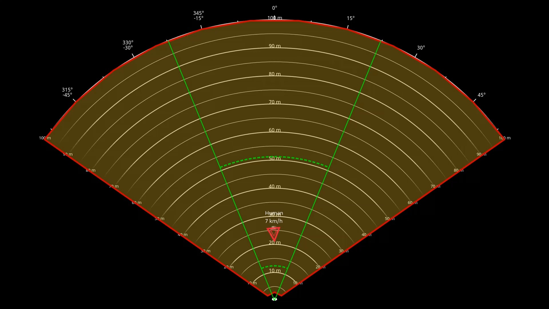
Once the radar-video fusion camera has been installed, the radar coverage is fixed. The field of view of the camera, however, depends on the zoom level of the lens.
To visualize the camera’s field of view in relation to the radar coverage, there are two green lines in the radar stream that represent the approximate field of view of the camera. The lines will adjust when the camera zooms in or out. Additionally, there are two dotted lines that represent the approximate area in which the camera can see. The dotted line closer to the device represent the near detection limit, while the one farther away represents the far detection limit.
The solid green lines represent the approximate field of view of the camera, while the dotted green lines represent the approximate near and far detection limits.
Zoom level examples
The size of the analytics fusion zone is affected by the zoom level of the lens in AXIS Q1656-DLE. The two extremes of the zoom level are described below.
Lens zoomed out (max wide)
When the lens in AXIS Q1656-DLE is zoomed out maximally, objects can get too small to detect for the video analytics. In this scenario, it's likely that objects will be detected by the radar with its wide coverage, but not by the video analytics. If you want to establish visual confirmation in the entire detection range of the radar, you can pair AXIS Q1656-DLE with one or more PTZ cameras.
Lens zoomed in (max tele)
When the lens is zoomed in maximally, it will limit the camera’s field of view significantly. However, since objects far away are magnified compared to when the lens is zoomed out maximally, it means the objects can be detected by the video analytics at a much larger distance from the device. In this scenario, it’s possible that objects will be detected by the video analytics but not by the radar analytics.
To maximize the chance of accurately classifying an object by both the radar and the video analytics, adjust the zoom – if possible – so that objects in the area of interest are large enough for the video analytics to detect them.
Radar-video detections and classifications
Since AXIS Q1656-DLE can detect and classify objects using radar and video — or just one of the technologies — there are several things to be aware of.
If two people are walking close together and are detected by the radar, but not the video analytics, they will be classified as one person and only one bounding box will surround them. When they enter the analytics fusion zone and visual confirmation is achieved, they will be accurately classified. The spatial differentiation of the radar in AXIS Q1656-DLE is 3 m(9 ft).
If an object is outside the camera's field of view, AXIS Q1656-DLE can't fuse any detections or classifications into the image plane. This means that AXIS Object Analytics can't trigger an alarm. To trigger an alarm when an object is detected by the radar only, configure a scenario in the radar’s web interface and use conditions to trigger on motion within the radar scenario.
The exclude zones you add in the radar’s web interface are global, which means that any motion detected in these zones will always be ignored – even if the exclude zone overlaps with the analytics fusion zone in AXIS Object Analytics. The exclude zones you add in AXIS Object Analytics, however, will only ignore motion in AXIS Object Analytics scenarios.
Area installation
To get the best radar performance in area installations, select the area monitoring profile in AXIS Q1656-DLE. For more information, see Select a radar profile.
Area installation examples
You can place multiple radar-video fusion cameras side-by-side to create a virtual fence, for example along or around a building.
For 180° radar coverage, place two AXIS Q1656-DLE next to each other. When you install more than one pair of radar-video fusion cameras side-by-side, we recommend placing them with 100 m (330 ft) spacing between each pair, as shown in the example.
Four pairs of AXIS Q1656-DLE mounted side-by-side.
You can install up to eight radar-video fusion cameras close together without interference between the radars. For more information about placing Axis radar devices close together, see Install multiple Axis radar devices.
Area monitoring use cases
Cover an open field around a building
A company in an office building needs to secure the premises from intrusion and vandalism, particularly after working hours, on weekends and on public holidays. To cover the area around the building, they install a combination of radar-video fusion cameras and PTZ cameras. They configure the radar-video fusion cameras to trigger an alarm when humans and vehicles approach the building. To get as reliable detections and classifications as possible, they select a detection sensitivity in AXIS Object Analytics suitable for the area. For more information about detection sensitivity, see Select detection sensitivity.
To make sure they get visual confirmation of potential intruders in the entire detection range of the radar, they add two PTZ cameras with built-in IR on the opposite corners of the building. The radars steer the PTZ cameras through AXIS Radar Autotracking for PTZ, and the built-in IR also provides more light for the radar-video fusion cameras, which makes it possible to detect and identify intruders on a greater distance.
Cover a fenced building
A warehouse that normally keeps goods on the premises is surrounded by a fence to keep intruders away. To detect potential trespassers, they install a combination of radar-video fusion cameras and PTZ cameras with built-in IR to secure the premises. The radar-video fusion cameras provide reliable detections and trigger alarms, while the PTZ cameras extend the visual coverage. The PTZ cameras’ built-in IR also provides more light for the radar-video fusion cameras, which makes it possible to detect and identify intruders on a greater distance.
In this scene, the area outside the fence is not covered since it’s a busy area that can trigger false alarms. In scenes with less activity, the area outside the fence could be covered as well. In such a scene, it would be possible to configure the cameras to trigger external lights when movement is detected outside the fence to deter potential intruders. They could also trigger an alarm when intruders are actually detected inside the fence. To be able to detect movement outside the fence, the cameras need to be mounted high enough.
Cover a critical asset
A telecom shelter that contains critical equipment and cabling is surrounded by a fence to keep intruders away. To avoid tampering and sabotage, they need additional protection. Since it’s important to keep false alarms to a minimum, they install two radar-video fusion cameras in the opposite corners of the site. The cameras can together cover the shelter, the antennas and the grounds. With the use of both the radar and video technology in the radar-video fusion cameras, the cameras can provide reliable detections and classifications of potential trespassers.
It’s possible to place radar-video fusion cameras facing each other in this way without interference between the radars. However, to make sure the video technology can provide accurate detections and classifications, good lighting conditions are required.
Cover the area around a loading bay
The loading bay of a commercial building is surrounded by a fence to protect the premises. For additional security, the company installs a thermal camera and three radar-video fusion cameras on the site. To detect potential trespassers, they install a thermal camera along the fence. To detect intruders that have managed to pass the fence, they install two of the radar-video fusion cameras on a pole facing the loading docks. These cameras will be able to detect and classify humans and vehicles moving around the docks and can trigger an alarm after working hours. To detect any intruders coming through the area with the turning point on the right side, they install an additional radar-video fusion camera facing the area. Finally, the thermal camera can also help to detect tampering attempts of the two cameras installed close to the fence.
Road installation
To get the best radar performance in road installations, select the road monitoring profile in AXIS Q1656-DLE. For more information, see Select a radar profile.
Road installation examples
When monitoring roads and highways, make sure to mount the radar-video fusion camera at a sufficient height to avoid blind spots (radar shadow) behind the vehicles.
Note
The size of the radar shadow depends on the radar-video fusion camera’s mounting height and the vehicles’ height and distance from the radar. For example, when a vehicle with a height of 4.5 m (15 ft) is 50 m (164 ft) away from a radar-video fusion cameras that is mounted at a height of 8 m (26 ft), the radar shadow behind the vehicle will be 50 m (164 ft). However, if the radar-video fusion camera is mounted at a height of 12 m (39 ft), the shadow behind the same vehicle will only be 23 m (74 ft).
Side mounted
To monitor vehicles travelling along a road you can mount the radar-video fusion camera on the side of the road, for example on a pole. In this type of installation, we recommend a pan angle of max 25°.
To make it possible for the radar in AXIS Q1656-DLE to measure high speeds accurately, position the radar-video fusion camera within a lateral distance of 10 m (32 ft) from the vehicles. For more information about detection range and velocity accuracy, see Road detection range.
Center mounted
To monitor vehicles on a multi-lane road, you can mount one or more radar-video fusion cameras on a gantry above the road.
The same type of installation is possible if you want to monitor vehicles that drive away from the radar-video fusion camera, instead of driving towards it.
You can also place the radar-video fusion camera on a gantry overlooking a pedestrian crossing with traffic lights, for example to log the speeds of departing vehicles, or detect speed violations.
To make it possible for the radar in AXIS Q1656-DLE to measure high speeds accurately, position the radar-video fusion camera within a lateral distance of 10 m (32 ft) from the vehicles. For more information about detection range and velocity accuracy, see Road detection range.
Road monitoring use cases
Wrong-way detection on a highway ramp
To detect and identify vehicles driving in the wrong direction on a highway ramp, traffic control mounts AXIS Q1656-DLE on a pole facing the ramp. For reliable detections, they set up a line crossing scenario in the radar pages of the device’s web interface and configure it so that vehicles must cross two lines to trigger an alarm. In the radar scenario, they position the two lines on the ramp as seen in the illustration and specify the driving direction and speeds to trigger on. With this configuration, the radar will trigger the alarm, and the camera can provide visual identification of the vehicle on the ramp. For information about how to set up a radar scenario, see Add scenarios.
Monitor traffic flow at an intersection – queue build-up
To monitor how and when queues build up in a busy intersection, traffic control installs AXIS Q1656-DLE on a gantry above the intersection. They set up an object in area scenario in AXIS Object Analytics that will trigger on vehicles moving in an area. They shape the scenario to only cover the part of the road leading up to the intersection and select a detection sensitivity that suits the scene. To trigger an alarm when queues start to build up, they configure the scenario to trigger on vehicles moving at speeds below 5 km/h (3 mph). For information about how to configure an AXIS Object Analytics scenario and select a suitable detection sensitivity, see Configure AXIS Object Analytics.
Monitor traffic flow at an intersection – direction
To get an overview of the traffic flow and the direction vehicles travel in a busy intersection, traffic control installs AXIS Q1656-DLE on a gantry above the road leading up to the intersection. They set up a line crossing scenario in the radar pages of the device’s web interface where vehicles must cross two lines to trigger an alarm. When they configure the radar scenario, they place the first of the two lines over the lanes leading up to the intersection, just after the pedestrian crossing to avoid vehicles stopping at the line. They place the second line over the lanes leading to the right. The vehicles must cross both lines in the specified direction to trigger an alarm. To avoid triggering on more than one vehicle per crossing, they lower the minimum trigger duration in the radar scenario from 2 to 0 seconds.
To monitor the traffic flow in all directions, they create one radar scenario for each direction. For information about how to set up a radar scenario, see Add scenarios.
Note
The radar scenario doesn’t count the vehicles crossing the lines, instead you can use the event system in the device’s web interface to keep count. One way to count vehicles is to send an MQTT message each time the radar scenario triggers, and count the triggers on the MQTT receiver side.
Get started
Find the device on the network
To find Axis devices on the network and assign them IP addresses in Windows®, use AXIS IP Utility or AXIS Device Manager. Both applications are free and can be downloaded from axis.com/support.
You can use the device with the following browsers:
ChromeTM
EdgeTM
Firefox®
Safari®
Windows®
✓
✓
*
*
macOS®
✓
✓
*
*
Linux®
✓
✓
*
*
Other operating systems
*
*
*
*
✓: Recommended *: Supported with limitations
Open the device's web interface
Open a browser and type the IP address or host name of the Axis device.
If you don’t know the IP address, use AXIS IP Utility or AXIS Device Manager to find the device on the network.
Type the username and password. If you access the device for the first time, you must create an administrator account. See Create an administrator account.
For descriptions of all features and settings in the web interface of devices with AXIS OS, see AXIS OS web interface help.
Create an administrator account
The first time you log in to your device, you must create an administrator account.
The device has no default account. If you lose the password for your administrator account, you must reset the device. See Reset to factory default settings.
Secure passwords
Important
Use HTTPS (which is enabled by default) to set your password or other sensitive configurations over the network. HTTPS enables secure and encrypted network connections, thereby protecting sensitive data, such as passwords.
The device password is the primary protection for your data and services. Axis devices do not impose a password policy as they may be used in various types of installations.
To protect your data we strongly recommend that you:
Use a password with at least 8 characters, preferably created by a password generator.
Don’t expose the password.
Change the password at a recurring interval, at least once a year.
Make sure that no one has tampered with the device software
To make sure that the device has its original AXIS OS, or to take full control of the device after a security attack:
This section includes instructions about configuring your device. If you want to learn more about how certain features work, go to Learn more.
Select exposure mode
To improve image quality for specific surveillance scenes, use exposure modes. Exposure modes lets you control aperture, shutter speed, and gain. Go to Video > Image > Exposure and select between the following exposure modes:
For most use cases, select Automatic exposure.
For environments with certain artificial lighting, for example fluorescent lighting, select Flicker-free.
Select the same frequency as the power line frequency.
For environments with certain artificial light and bright light, for example outdoors with fluorescent lighting at night and sun during daytime, select Flicker-reduced.
Select the same frequency as the power line frequency.
To lock the current exposure settings, select Hold current.
Optimize IR illumination
Depending on the installation environment and the conditions around the camera, for example external light sources in the scene, you can sometimes improve the image quality if you manually adjust the intensity of the LEDs. If you have problems with reflections from the LEDs, you can try to reduce the intensity.
Go to Video > Image > Day-night mode.
Turn on Allow illumination.
Click in the live view and select Manual.
Adjust the intensity.
Benefit from IR light in low-light conditions by using night mode
Your camera uses visible light to deliver color images during the day. But as the visible light diminishes, color images become less bright and clear. If you switch to night mode when this happens, the camera uses both visible and near-infrared light to deliver bright and detailed black-and-white images instead. You can set the camera to switch to night mode automatically.
Go to Video > Image > Day-night mode, and make sure that the IR-cut filter is set to Auto.
To use the built-in IR light when the camera is in night mode, turn on Allow illumination and Synchronize illumination.
Reduce noise in low-light conditions
To reduce noise in low-light conditions, you can adjust one or more of the following settings:
Adjust the trade-off between noise and motion blur. Go to Video > Image > Exposure and move the Blur-noise trade-off slider toward Low noise.
Set the exposure mode to automatic.
Note
A high max shutter value can result in motion blur.
To slow down the shutter speed, set max shutter to the highest possible value.
Note
When you reduce the max gain, the image can become darker.
Set the max gain to a lower value.
If there is an Aperture slider, move it towards Open.
Reduce sharpness in the image, under Video > Image > Appearance.
Reduce motion blur in low-light conditions
To reduce motion blur in low-light conditions, adjust one or more of the following settings in Video > Image > Exposure:
Note
When you increase the gain, image noise also increases.
Set Max shutter to a shorter time, and Max gain to a higher value.
If you still have problems with motion blur:
Increase the light level in the scene.
Mount the camera so that objects move toward it or away from it rather than sideways.
Maximize the details in an image
Important
If you maximize the details in an image, the bitrate will probably increase and you might get a reduced frame rate.
Make sure to select the capture mode that has the highest resolution.
Go to Video > Stream > General and set the compression as low as possible.
Below the live view image, click and in Video format, select MJPEG.
Go to Video > Stream > Zipstream and select Off.
Handle scenes with strong backlight
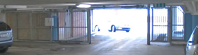
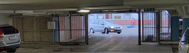
Dynamic range is the difference in light levels in an image. In some cases the difference between the darkest and the brightest areas can be significant. The result is often an image where either the dark or the bright areas are visible. Wide dynamic range (WDR) makes both dark and bright areas of the image visible.
Image without WDR.Image with WDR.
Note
WDR can cause artifacts in the image.
WDR may not be available for all capture modes.
Go to Video > Image > Wide dynamic range.
Turn on WDR.
Use the Local contrast slider to adjust the amount of WDR.
If you still have problems, go to Exposure and adjust the Exposure zone to cover the area of interest.
Image stabilization is suitable in environments where the product is mounted in an exposed location where vibrations can occur, for example, due to wind or passing traffic.
The feature makes the image smoother, steadier, and less blurry. It also reduces the file size of the compressed image and lowers the bitrate of the video stream.
Note
When you turn on image stabilization, the image is slightly cropped, which lowers the maximum resolution.
Go to Video > Installation > Image correction.
Turn on Image stabilization.
Hide parts of the image with privacy masks
You can create one or several privacy masks to hide parts of the image.
Go to Video > Privacy masks.
Click .
Click the new mask and type a name.
Adjust the size and placement of the privacy mask according to your needs.
To change the color for all privacy masks, click Privacy masks and select a color.
You can add an image as an overlay in the video stream.
Go to Video > Overlays.
Click Manage images.
Upload or drag and drop an image.
Click Upload.
Select Image from the drop-down list and click .
Select the image and a position. You can also drag the overlay image in the live view to change the position.
Show the radar live view in the image
Use onscreen controls to see both the live view of the video and the radar in the same stream.
Go to Video > Image.
Click in the live view to access the product’s onscreen controls.
Select Predefined controls.
Turn on Radar picture-in-picture.
Click Enable picture-in-picture.
To change the size of the radar projection, click Resize picture-in-picture.
To change the position of the radar projection, click Move picture-in-picture.
Add street names and compass direction to the image
Note
The street name and compass direction will be visible on all video streams and recordings.
Go to Apps.
Select axis-orientationaid.
Click Open.
To add a street name, click Add text and modify the text to fit the street.
To add a compass, click Add compass and modify the compass to fit the image.
Record and watch video
Record video directly from the camera
Go to Video > Stream.
To start a recording, click .
If you haven’t set up any storage, click and . For instructions on how to set up network storage, see Set up network storage
To stop recording, click again.
Watch video
Go to Recordings.
Click for your recording in the list.
View and record video
This section includes instructions about configuring your device. To learn more about how streaming and storage works, go to Streaming and storage.
Reduce bandwidth and storage
Important
Reducing the bandwidth can lead to loss of detail in the image.
Go to Video > Stream.
Click in the live view.
Select Video format AV1 if your device supports it. Otherwise select H.264.
Go to Video > Stream > General and increase Compression.
Go to Video > Stream > Zipstream and do one or more of the following:
Note
The Zipstream settings are used for all video encodings except MJPEG.
Select the Zipstream Strength that you want to use.
Turn on Optimize for storage. This can only be used if the video management software supports B-frames.
Turn on Dynamic FPS.
Turn on Dynamic GOP and set a high Upper limit GOP length value.
Note
Most web browsers don’t support H.265 decoding and because of this the device doesn’t support it in its web interface. Instead you can use a video management system or application that supports H.265 decoding.
Set up network storage
To store recordings on the network, you need to set up your network storage.
Go to System > Storage.
Click Add network storage under Network storage.
Type the IP address of the host server.
Type the name of the shared location on the host server under Network share.
Type the username and password.
Select the SMB version or leave it on Auto.
Select Add share without testing if you experience temporary connection issues, or if the share is not yet configured.
Click Add.
Configure the radar
Note
The radar-video fusion camera is factory-calibrated so that the camera and radar module are perfectly aligned. Do not move or remove the lens, optical unit or radar module since this will undo the calibration and alignment.
Select a radar profile
The radar in this radar-video fusion camera has two profiles; one that is optimized for area monitoring, and one that is optimized for road monitoring. Select the profile that suits your type of installation.
In the web interface:
Go to Radar > Settings > Detection.
Select a profile under Radar profiles.
Set the mounting height
Set the mounting height of the device in the radar's web interface. This helps the radar to detect and measure the speed of passing objects correctly.
Measure the height from the ground up to the device as accurately as possible. For scenes with uneven surfaces, set the value that represents the average height in the scene.
Note
If the height is set incorrectly , the bounding boxes that appear in AXIS Object Analytics when an object is detected will not appear in the accurate position.
Go to Radar > Settings > General.
Set the height under Mounting height.
You can also set the mounting height in AXIS Object Analytics. Setting the height in one place will automatically populate the mounting height in the other.
Go to Apps > AXIS Object Analytics.
Turn on the application and click Open.
Click Settings.
Set the height under Mounting height.
Validate the mounting height
To validate that you have measured and set the correct mounting height of the device, add an augmented overlay in the camera’s live view. The overlay consists of white bounding boxes projected around moving objects.
Go to Video > Image.
Click in the live view to access the device’s onscreen controls.
Expand Predefined controls.
Turn on Augmented overlay (radar).
Click Toggle augmented bounding boxes.
Ask someone to move in the scene you’re monitoring and check in the camera’s live view that the bounding boxes are projected around the moving objects, and not above, below, or next to them.
If necessary, re-measure the mounting height, adjust the settings, and check again.
Turn off the augmented overlay when you’re done with the validation.
Note
If the scene contains variations in elevation, use the autocalibration feature to improve the accuracy of the bounding boxes based on radar detections. For more information, see Autocalibrate the device.
Calibrate a reference map
To make it easier to see where detected objects are moving, you can upload a map for reference. You can use a ground plan or an aerial photo that shows the area covered by the radar. Calibrate the map so the radar view fits the position, direction, and scale of the map, and zoom in on the map if you're interested in a specific part of the scene.
You can either use a setup assistant that takes you through the map calibration step by step, or edit each setting individually.
Use the setup assistant:
Go to Radar > Map calibration.
Click Setup assistant and follow the instructions.
To remove the uploaded map and the settings you have added, click Reset calibration.
Edit each setting individually:
The map will calibrate gradually after you adjust each setting.
Go to Radar > Map calibration > Map.
Select the image you want to upload, or drag and drop it in the designated area.
To reuse a map image with its current pan and zoom settings, click Download map.
Under Rotate map, use the slider to rotate the map into position.
Go to Scale and distance on a map and click on two pre-determined points on the map.
Under Distance, add the actual distance between the two points you have added to the map.
Go to Pan and zoom map and use the buttons to pan the map image, or zoom in and out on the map image.
Note
The zoom function doesn’t alter the radar’s area of coverage. Even if parts of the coverage is out of view after zooming, the radar will still detect moving objects in the entire area of coverage. The only way to exclude detected movement is to add exclude zones. For more information, see Add exclude zones.
Go to Radar position and use the buttons to move or rotate the position of the radar on the map.
To remove the uploaded map and the settings you have added, click Reset calibration.
The video shows an example of how to calibrate a reference map in an Axis radar or radar-video fusion camera.
Set detection zones
To determine where to detect motion, you can add one or more detection zones. Use different zones to trigger different actions.
There are two types of zones:
A scenario (previously called include zone) is an area in which moving objects will trigger rules. The default scenario matches the entire area covered by the radar.
An exclude zone is an area in which moving objects will be ignored. Use exclude zones if there are areas inside a scenario that trigger a lot of unwanted alarms.
Add scenarios
A scenario is a combination of triggering conditions and detection settings, which you can use to create rules in the event system. Add scenarios if you want to create different rules for different parts of the scene.
Add a scenario:
Go to Radar > Scenarios.
Click Add scenario.
Type the name of the scenario.
Select if you want to trigger on objects moving in an area or on objects crossing one, or two, lines.
Trigger on objects moving in an area:
Select Movement in area.
Click Next.
Select the type of zone that should be included in the scenario.
Use the mouse to move and shape the zone so that it covers the desired part of the radar image or reference map.
Click Next.
Add detection settings.
Add seconds until trigger after under Ignore short-lived objects.
Select which object type to trigger on under Trigger on object type.
Add a range for the speed limit under Speed limit.
Click Next.
Set the minimum duration of the alarm under Minimum trigger duration.
Click Save.
Trigger on objects crossing a line:
Select Line crossing.
Click Next.
Position the line in the scene.
Use the mouse to move and shape the line.
To change the detection direction, turn on Change direction.
Click Next.
Add detection settings.
Add seconds until trigger after under Ignore short-lived objects.
Select which object type to trigger on under Trigger on object type.
Add a range for the speed limit under Speed limit.
Click Next.
Set the minimum duration of the alarm under Minimum trigger duration.
The default value is set to 2 seconds. If you want the scenario to trigger every time an object crosses the line, lower the duration to 0 seconds.
Click Save.
Trigger on objects crossing two lines:
Select Line crossing.
Click Next.
To make the object cross two lines for the alarm to trigger, turn on Require crossing of two lines.
Position the lines in the scene.
Use the mouse to move and shape the line.
To change the detection direction, turn on Change direction.
Click Next.
Add detection settings.
Set the time limit between crossing the first and the second line under Max time between crossings.
Select which object type to trigger on under Trigger on object type.
Add a range for the speed limit under Speed limit.
Click Next.
Set the minimum duration of the alarm under Minimum trigger duration.
The default value is set to 2 seconds. If you want the scenario to trigger every time an object has crossed the two lines, lower the duration to 0 seconds.
Click Save.
Add exclude zones
Exclude zones are areas in which moving objects will be ignored. Add exclude zones to ignore, for example, swaying foliage on the side of a road. You could also add exclude zones to ignore ghost tracks caused by radar-reflective materials, for example a metal fence.
Add an exclude zone:
Go to Radar > Exclude zones.
Click Add exclude zone.
Use the mouse to move and shape the zone so that it covers the desired part of the radar view or reference map.
Autocalibrate the device
Autocalibration of the radar-video fusion camera improves the accuracy of the bounding boxes that appear around detected objects in AXIS Object Analytics. With autocalibration, the device uses information from the video, like height and angular accuracy, to improve the positioning of the bounding boxes based on the radar detections.
Note
The autocalibration doesn’t affect the detections, only the visualization of the bounding boxes.
For elevation calibration:
Go to Radar > Autocalibration > Elevation.
Turn on Autocalibration.
The autocalibration occurs as soon as calibration data is available.
Select a Smoothing option.
If your scene contains little variation in elevation, leave Smoothing set to High.
If your scene is hilly or sloped, or if it contains stairs or high buildings, set Smoothing to Low to keep the differences in elevation.
Visualize the result of the calibration in the web interface with the following options:
Show elevation pattern shows the vertical distance from the ground up to the camera in a pattern of colored dots.
Show color legend shows a legend containing the colors of the elevation pattern and the vertical distance that each color represent.
Show reference area shows the area which the calibration is based on.
For azimuth calibration:
Go to Radar > Autocalibration > Azimuth.
Turn on Autocalibration.
The autocalibration occurs as soon as calibration data is available.
Show a text overlay with the tilt angle of the radar
You can add an overlay in the radar’s live view that shows the tilt angle of the radar. This is helpful during installation, or whenever you need to know the tilt angle of the device.
Note
The tilt angle overlay shows “90” when the device is horizontal. If the overlay shows “75”, the tilt angle of the radar is 15° below the horizon.
Go to Radar > Overlays.
Select Text and click .
Type #op.
You can also click Modifier and select #op from the list.
Select a position. You can also drag the overlay field in the live view to change the position.
Configure AXIS Object Analytics
AXIS Object Analytics is an AI-based application that detects and classifies moving objects. It’s also the main interface for configuring the radar-video fusion in AXIS Q1656-DLE. The real-time output of the fusion can only be seen in the video stream inside a scenario configured in the application.
Create a scenario
Use scenarios in AXIS Object Analytics to define the detection settings and triggering conditions for your radar-video fusion camera.
In the device’s web interface, go to Apps > AXIS Object Analytics.
Start the application and click Open.
In the welcome screen, click Step-by-step and follow the recommended setup procedure.
In Considerations, read through the information and click Finish.
Click + New scenario.
Note
By default, the scenarios Object in area and Line crossing use both video and radar input. The other scenarios in AXIS Object Analytics use video input only.
Select a scenario based on your requirements.
Select the type of object you want the application to detect.
Configure your scenario.
Verify your settings and click Finish.
Note
To get bounding boxes around the moving objects, go to Settings and turn on Metadata overlay. When you create two scenarios, where one scenario uses both video and radar input and the other only uses video input, there will be double bounding boxes around the moving object. This behavior is expected.
You have now created a scenario in AXIS Object Analytics. To modify the scenario and apply additional settings, click Open. For scenarios that use both radar and video input, you can use speed to trigger and select a detection sensitivity. For instructions, see:
Some of the considerations and features described in AXIS Object Analytics user manual don’t apply to radar-video fusion cameras.
Use speed to trigger
If you have created an Object in area or Line crossing scenario in AXIS Object Analytics, you can trigger on objects moving within a set speed range, or above and below it.
Go to Apps > AXIS Object Analytics.
Start the application and click Open.
Select the scenario you want to modify and click Open.
Go to Object speed and turn on Use speed to trigger.
Set the speed range to trigger on.
If you want to trigger on speeds above and below your set range, click Invert.
Select detection sensitivity
With the option to select detection sensitivity, you can decide if you want to trigger on detections made by either the video or the radar, or detections made by both. You can also let the device itself, based on the fusion algorithms, decide if it should rely on one of the technologies, or both.
This option is available in Object in area and Line crossing scenarios.
Go to Apps > AXIS Object Analytics.
Start the application and click Open.
Select the scenario you want to modify and click Open.
Go to Detection sensitivity and select one of the following options:
Low sensitivity: Requires both the radar and the camera to detect the object. This reduces the risk of false alarms, but increases the risk of missed detections.
To make sure that objects can be detected by both technologies, the scene can't be too complex. The light conditions need to be good, the detection area needs to be within the detection range of both technologies, and there should preferably not be any disturbing elements, such as trees or bushes.
Automatic: Lets the application decide if both the radar and the camera, or only one of them, is required to detect the object. This is the default option.
High sensitivity: Requires either the radar or the camera to detect the object. This increases the risk of false alarms, but reduces the risk of missed detections.
The lighting conditions and the size of the detection area are less important when you select high sensitivity since you only need one of the technologies to detect the object.
Note
You can improve the accuracy of the bounding boxes that appear around detected objects in AXIS Object Analytics with the autocalibration feature. Autocalibration doesn’t affect the detections, only the visualization of the bounding boxes.
If you notice that you get too many false alarms, you can filter out certain types of movement or objects, change the coverage, or adjust the detection sensitivity. See which settings work best for your environment.
Adjust the detection sensitivity of AXIS Object Analytics:
Go to Apps > AXIS Object Analytics, open a scenario, and select a lower Detection sensitivity.
Low sensitivity: Requires both the radar and the camera to detect the object. Reduced risk of false alarms, but increased risk of missed detections.
Automatic: Lets the application decide if both radar and camera or only one of them is required to detect the object.
High sensitivity: Requires either the radar or the camera to detect the object. Increased risk of false alarms but reduced risk of missed detections.
Adjust the detection sensitivity of the radar:
Go to Radar > Settings > Detection and select a lower Detection sensitivity. This decreases the risk of false alarms, but it could also cause the radar to miss some movement.
Low: Use this sensitivity when there are a lot of metal objects or large vehicles in the area. It will take longer time for the radar to track and classify objects. This can reduce the detection range, especially for fast moving objects.
Medium: This is the default setting.
High: Use this sensitivity when you have an open field without metal objects in front of the radar. This will increase the detection range for humans.
Modify scenarios and exclude zones:
If a scenario includes hard surfaces, such as a metal wall, there may be reflections that causes multiple detections for a single physical object. You can either modify the shape of the scenario, or add an exclude zone that ignores certain parts of the scenario. For more information, see Add scenarios and Add exclude zones.
Trigger on objects crossing two lines instead of one:
If a line crossing scenario includes swaying objects or animals moving around, there is a risk that an object will happen to cross the line and trigger a false alarm. In this case, you can configure the scenario to trigger only when an object has crossed two lines. For more information, see Add scenarios.
Filter on movement:
Go to Radar > Settings > Detection and select Ignore swaying objects. This setting minimizes false alarms from trees, bushes, and flagpoles in the coverage zone.
Go to Radar > Settings > Detection and select Ignore small objects. This setting minimizes false alarms from small objects in the coverage zone, such as cats and rabbits.
Filter on time:
Go to Radar > Scenarios.
Select a scenario, and click to modify its settings.
Select a higher value under Seconds until trigger. This is the delay time from when the radar starts tracking an object until it can trigger and alarm. The timer starts when the radar first detects the object, not when the object enters the specified zone in the scenario.
Filter on object type:
Go to Radar > Scenarios.
Select a scenario, and click to modify its settings.
To avoid triggering on specific object types, deselect the object types that should not trigger events in the scenario.
Note
The object type setting only affects the radar. It will be ignored by AXIS Object Analytics.
This example explains how to turn on power saving mode when no motion is detected in the scene.
Note
When you turn on power saving mode, the IR illumination range is reduced.
Make sure that AXIS Object Analytics is running:
Go to Apps > AXIS Object Analytics.
Start the application if it is not already running.
Make sure you have set up the application according to your needs.
Create a rule:
Go to System > Events and add a rule.
Type a name for the rule.
In the list of conditions, under Application, select Object Analytics.
Select Invert this condition.
In the list of actions, under Power saving mode, select Use power saving mode while the rule is active.
Click Save.
Trigger a notification when the enclosure is opened
This example explains how to set up an email notification when the housing or casing of the device is opened.
Add an email recipient:
Go to System > Events > Recipients and click Add recipient.
Type a name for the recipient.
Select Email as the notification type.
Type the recipient’s email address.
Type the email address that you want the camera to send notifications from.
Provide the login details for the sending email account, along with the SMTP hostname and port number.
To test your email setup, click Test.
Click Save.
Create a rule:
Go to System > Events > Rules and click Add a rule.
Type a name for the rule.
In the list of conditions, select Casing open.
In the list of actions, select Send notification to email.
Select a recipient from the list.
Type a subject line and message for the email.
Click Save.
Send an email if someone covers the radar with a metallic object
This example explains how to create a rule that sends an email notification when someone tampers with the radar by covering it with a metallic object, such as metallic foil or a metallic sheet.
Add an email recipient:
Go to System > Events > Recipients and add a recipient.
Type a name for the recipient.
Under Type, select Email.
Type an email address to send the email to.
Fill in the rest of the information according to your email provider.
The radar device doesn’t have its own email server, so it needs to log into an email server to send emails.
To send a test email, click Test.
Click Save.
Create a rule:
Go to System > Events and add a rule.
Type a name for the rule, for example Tampering mail.
From the list of conditions, under Device status, select Radar data failure.
Under Reason, select Tampering.
In the list of actions, under Notifications, select Send notification to email.
Select the recipient you created.
Type a subject and a message for the email.
Click Save.
Control a PTZ camera with the radar
It’s possible to use the information about objects’ positions from the radar to make a PTZ camera track objects. There are two ways to do this:
Use an NTP server to synchronize the time on the cameras and the Windows computer. If the clocks are out of sync, you may experience delays in the tracking, or ghost tracking.
Control a PTZ camera with the built-in radar autotracking service
The built-in radar autotracking creates an edge-to-edge solution where the radar directly controls the PTZ camera. It supports all Axis PTZ cameras.
Note
You can use the built-in radar autotracking service to connect one radar with one PTZ camera. For a setup where you want to use more than one radar or PTZ camera, use AXIS Radar Autotracking for PTZ. For more information, see Control a PTZ camera with AXIS Radar Autotracking for PTZ.
This instruction explains how to pair the radar with a PTZ camera, how to calibrate the devices, and how to set up the tracking of objects.
Before you start:
Define the area of interest and avoid unwanted alarms by setting up exclude zones in the radar. Make sure to exclude zones with radar-reflective materials or swaying objects, like foliage, to prevent the PTZ camera from tracking irrelevant objects. For instructions, see Add exclude zones.
Pair the radar with the PTZ camera:
Go to System > Edge-to-edge > PTZ pairing.
Enter the IP address, username and password for the PTZ camera.
Click Connect.
Click Configure Radar autotracking or go to Radar > Radar PTZ autotracking to set up radar autotracking.
Calibrate the radar and the PTZ camera:
Go to Radar > Radar PTZ autotracking.
To set the mounting height of the camera, go to Camera mounting height.
To pan the PTZ camera so that it points in the same direction as the radar, go to Pan alignment.
If you need to adjust the tilt to compensate for a sloping ground, go to Ground incline offset and add an offset in degrees.
Set up the PTZ tracking:
Go to Track to select if you want to track humans, vehicles and/or unknown objects.
To start tracking objects with the PTZ camera, turn on Tracking.
The tracking automatically zooms in on an object, or a group of objects, to keep them in the view of the camera.
Turn on Object switching if you expect multiple objects that won’t fit in the camera view.
With this setting, the radar gives priority of the objects to track.
To determine how many seconds to track each object, set Object hold time.
To make the PTZ camera return to its home position when the radar no longer tracks any objects, turn on Return to home.
To determine how long the PTZ camera should stay at the tracked objects last known position before returning to home, set Return to home timeout.
To fine tune the zoom of the PTZ camera, adjust the zoom on the slider.
Control a PTZ camera with AXIS Radar Autotracking for PTZ
AXIS Radar Autotracking for PTZ is a server-based solution that can handle different setups when tracking objects:
Control several PTZ cameras with one radar.
Control one PTZ camera with several radars.
Control several PTZ cameras with several radars.
Control one PTZ camera with one radar when they are mounted in different positions covering the same area.
Use the radar-video fusion camera with the application AXIS Speed Monitor to collect radar data for detected objects and send it over MQTT.
This example explains how to set up an MQTT client in the device where you have installed AXIS Speed Monitor, and how to create a condition that will publish the radar data collected in AXIS Speed Monitor as a payload to an MQTT broker.
Before you start:
Install AXIS Speed Monitor in your radar-video fusion camera, or install it in a camera that you connect to the radar in the radar-video fusion camera.
Set up the MQTT client in the web interface of the device where you have installed AXIS Speed Monitor:
Go to System > MQTT > MQTT client > Broker and enter the following information:
Host: The broker IP address
Client ID: The ID of the device
Protocol: The protocol the broker is set to
Port: The port number used by the broker
The broker Username and Password
Click Save and Connect.
Create a condition that publishes the radar data as a payload to the MQTT broker:
Go to System > MQTT > MQTT publication and click + Add condition.
In the list of conditions, under Application, select Speed Monitor: Track exited zone.
The device will now be able to send information about the radar tracks for every moving object that exits a scenario. Every object will have its own radar track parameters, for example rmd_zone_name, tracking_id, and trigger_count. You can find the full list of parameters in AXIS Speed Monitor user manual.
Record video when the camera detects an object
This example explains how to set up the camera to start recording to the SD card when the camera detects an object. The recording will include five seconds before detection and one minute after detection ends.
Before you start:
Make sure you have an SD card installed.
Make sure that AXIS Object Analytics is running:
Go to Apps > AXIS Object Analytics.
Start the application if it is not already running.
Make sure you have set up the application according to your needs.
Create a rule:
Go to System > Events and add a rule.
Type a name for the rule.
In the list of conditions, under Application, select Object Analytics.
In the list of actions, under Recordings, select Record video while the rule is active.
In the list of storage options, select SD_DISK.
Select a camera and a stream profile.
Set the prebuffer time to 5 seconds.
Set the postbuffer time to 1 minute.
Click Save.
Provide visual indication of an ongoing event
You have the option to connect the AXIS I/O Indication LED to your network camera. This LED can be configured to turn on whenever certain events occur in the camera. For example, to let people know that video recording is in progress.
Required hardware
AXIS I/O Indication LED
An Axis network video camera
Note
For instructions on how to connect the AXIS I/O Indication LED, see the installation guide provided with the product.
The following example shows how to configure a rule that turns on the AXIS I/O Indication LED to indicate that camera is recording.
Go to System > Accessories > I/O ports.
For the port that you connected the AXIS I/O Indication LED to, click to set the direction to Output, and click to set the normal state to Circuit open.
Go to System > Events.
Create a new rule.
Select the Condition that must be met to trigger the camera to start recording. It can, for example, be a time schedule or motion detection.
In the list of actions, select Record video. Select a storage space. Select a stream profile or create a new. Also set the Prebuffer and Postbuffer as required.
Save the rule.
Create a second rule and select the same Condition as in the first rule.
In the list of actions, select Toggle I/O while the rule is active, and then select the port the AXIS I/O Indication LED is connected to. Set the state to Active.
Save the rule.
Other scenarios where AXIS I/O Indication LED can be used are for example:
Configure the LED to turn on when the camera starts, to indicate the presence of the camera. Select System ready as a condition.
Configure the LED to turn on when live stream is active to indicate that a person or a program is accessing a stream from the camera. Select Live stream accessed as a condition.
Show a text overlay in the video stream when the device detects an object
This example explains how to display the text “Motion detected” when the device detects an object.
Make sure that AXIS Object Analytics is running:
Go to Apps > AXIS Object Analytics.
Start the application if it is not already running.
Make sure you have set up the application according to your needs.
Add the overlay text:
Go to Video > Overlays.
Under Overlays, select Text and click .
Enter #D in the text field.
Choose text size and appearance.
To position the text overlay, click and select an option.
Create a rule:
Go to System > Events and add a rule.
Type a name for the rule.
In the list of conditions, under Application, select Object Analytics.
In the list of actions, under Overlay text, select Use overlay text.
Select a video channel.
In Text, type “Motion detected”.
Set the duration.
Click Save.
Note
If you update the overlay text it will be automatically updated on all video streams dynamically.
Record video when a PIR detector senses motion
This example explains how to connect a PIR detector (normally closed) to the device, and to start recording video when the detector senses motion.
Required hardware
3-wire cable (ground, power, I/O)
PIR detector, normally closed
NOTICE
Disconnect the device from power before connecting the wires. Reconnect to power after all connections are done.
Connect the wires to the device’s I/O connector
Note
For information on the I/O connector, see Connectors.
Connect the ground wire to pin 1 (GND/-).
Connect the power wire to pin 2 (12V DC output).
Connect the I/O wire to pin 3 (I/O input).
Connect the wires to the PIR detector’s I/O connector
Connect the other end of the ground wire to pin 1 (GND/-).
Connect the other end of the power wire to pin 2 (DC input/+).
Connect the other end of the I/O wire to pin 3 (I/O output).
Configure the I/O port in the device web interface
Go to System > Accessories > I/O ports.
Click to set the direction to input for port 1.
Give the input module a descriptive name, for example “PIR detector”.
If you want to trigger an event whenever the PIR detector senses motion, click to set the normal state to circuit closed.
Create a rule
Go to System > Events and add a rule.
Type a name for the rule.
In the list of conditions, select PIR detector.
In the list of actions, under Recordings, select Record video while the rule is active.
In the list of storage options, select SD_DISK.
Select a camera and a stream profile.
Set the prebuffer time to 5 seconds.
Set the postbuffer time to 1 minute.
Click Save.
Record video when the camera detects loud noises
This example explains how to set up the camera to start recording to the SD card five seconds before it detects loud noise and to stop two minutes after.
Note
The following instructions require that a microphone is connected to audio-in.
In the list of conditions, under Audio, select Audio Detection.
In the list of actions, under Recordings, select Record video.
In the list of storage options, select SD_DISK.
Select the stream profile where audio has been turned on.
Set the prebuffer time to 5 seconds.
Set the postbuffer time to 2 minutes.
Click Save.
Detect tampering with input signal
This example explains how to send an email when the input signal is cut or short-circuited. For more information about the I/O connector, see I/O connector.
Go to System > Accessories > I/O ports and turn on Supervised for the relevant port.
Add an email recipient:
Go to System > Events > Recipients and add a recipient.
Type a name for the recipient.
Select Email as the notification type.
Type the recipient’s email address.
Type the email address that you want the camera to send notifications from.
Provide the login details for the sending email account, along with the SMTP hostname and port number.
To test your email setup, click Test.
Click Save.
Create a rule:
Go to System > Events > Rules and add a rule.
Type a name for the rule.
In the list of conditions, under I/O, select Supervised input tampering is active.
Select the relevant port.
In the list of actions, under Notifications, select Send notification to email and then select the recipient from the list.
Type a subject line and message for the email.
Click Save.
Audio
Add audio to your recording
Turn on audio:
Go to Video > Stream > Audio and include audio.
If the device has more than one input source, select the correct one in Source.
Go to Audio > Device settings and turn on the correct input source.
Edit the stream profile that is used for the recording:
Go to System > Stream profiles and select the stream profile.
Select Include audio and turn it on.
Click Save.
Connect to a strobe siren
Network pairing allows you to pair a camera with a compatible Axis device with light and siren functionality. Once paired, the camera can configure and maintain both devices.
Pair the camera with a strobe siren:
Go to System > Edge-to-edge > Pairing.
Click Add and select the pairing type Network pairing from the drop-down list.
Type the IP address, username and password of the strobe siren.
Click Connect. A confirmation message appears.
To find devices directly on the network, click Discover devices.
Note
The list shows all Axis devices that are found, not only devices that can be paired.
An info icon is shown for devices that have already been paired. Hover over the icon to get information about pairings that are already active.
Make sure the paired devices run the same AXIS OS version.
Important
It’s only possible to discover devices where Bonjour is enabled. To enable Bonjour for a device, open its web interface and go to System > Network > Network discovery protocols.
The web interface
To read about all the features and settings available in the web interface of devices with AXIS OS, go to AXIS OS web interface help.
Learn more
Long-distance connections
This product supports fiber-optic cable installations through a media converter. Fiber-optic cable installations offer a number of benefits such as:
Long-distance connection
High speed
Long lifetime
Large capacity of data transmission
Electromagnetic interference immunity
Find out more about fiber-optic cable installations in the white paper “Long distance surveillance - Fiber-optic communication in network video” at axis.com/learning/white-papers.
For information about how to install the media converter see the Installation Guide for this product.
Capture modes
A capture mode is a preset configuration that defines how the camera captures images.
The capture mode setting can affect the maximum resolution and maximum frame rate available in the device.
The capture mode with a lower resolution than the maximum can reduce the field of view.
The capture mode also affects the shutter speed, which in turn affects the light sensitivity. This is because a capture mode with a high maximum frame rate has a reduced light sensitivity, and the other way around.
With some capture modes you can’t use WDR.
The lower resolution capture mode might be sampled from the original resolution, or it might be cropped out from the original, in which case the field of view could also be affected.
The image shows how the field of view and aspect ratio can change between two different capture modes.
What capture mode to choose depends on the requirements for the frame rate and resolution of the specific surveillance setup. For specifications about available capture modes, see the product’s datasheet at axis.com.
Remote focus and zoom
The remote focus and zoom functionality allows you to make focus and zoom adjustments to your camera from a computer. It is a convenient way to ensure that the scene’s focus, viewing angle and resolution are optimized without having to visit the camera’s installation location.
Privacy masks
A privacy mask is a user-defined area that covers a part of the monitored area. In the video stream, privacy masks appear either as blocks of solid color or with a mosaic pattern.
You’ll see the privacy mask on all snapshots, recorded video, and live streams.
You can use the VAPIX® application programming interface (API) to hide the privacy masks.
Important
If you use multiple privacy masks it may affect the product’s performance.
You can create several privacy masks. Each mask can have 3 to 10 anchor points.
Overlays
Overlays are superimposed over the video stream. They are used to provide extra information during recordings, such as a timestamp, or during product installation and configuration. You can add either text or an image.
The video streaming indicator is another type of overlay. It shows you that the live view video stream is live.
Note
Overlays are included in all video streams except SIP calls when the connection is over PoE class 3.
Streaming and storage
Video compression formats
Decide which compression method to use based on your viewing requirements, and on the properties of your network. The available options are:
Motion JPEG
Note
To ensure support for the Opus audio codec, the Motion JPEG stream is always sent over RTP.
Motion JPEG, or MJPEG, is a digital video sequence that is made up of a series of individual JPEG images. These images are then displayed and updated at a rate sufficient to create a stream that shows constantly updated motion. For the viewer to perceive motion video the rate must be at least 16 image frames per second. Full motion video is perceived at 30 (NTSC) or 25 (PAL) frames per second.
The Motion JPEG stream uses considerable amounts of bandwidth, but provides excellent image quality and access to every image contained in the stream.
H.264 or MPEG-4 Part 10/AVC
Note
H.264 is a licensed technology. The Axis product includes one H.264 viewing client license. To install additional unlicensed copies of the client is prohibited. To purchase additional licenses, contact your Axis reseller.
H.264 can, without compromising image quality, reduce the size of a digital video file by more than 80% compared to the Motion JPEG format and by as much as 50% compared to older MPEG formats. This means that less network bandwidth and storage space are required for a video file. Or seen another way, higher video quality can be achieved for a given bitrate.
H.265 or MPEG-H Part 2/HEVC
H.265 can, without compromising image quality, reduce the size of a digital video file by more than 25% compared to H.264.
Note
H.265 is licensed technology. The Axis product includes one H.265 viewing client license. Installing additional unlicensed copies of the client is prohibited. To purchase additional licenses, contact your Axis reseller.
Most web browsers don’t support H.265 decoding and because of this the camera doesn’t support it in its web interface. Instead you can use a video management system or application supporting H.265 decoding.
How do Image, Stream, and Stream profile settings relate to each other?
The Image tab contains camera settings that affect all video streams from the product. If you change something in this tab, it immediately affects all video streams and recordings.
The Stream tab contains settings for video streams. You get these settings if you request a video stream from the product and don’t specify for example resolution, or frame rate. When you change the settings in the Stream tab, it doesn’t affect ongoing streams, but it will take effect when you start a new stream.
The Stream profiles settings override the settings from the Stream tab. If you request a stream with a specific stream profile, the stream contains the settings of that profile. If you request a stream without specifying a stream profile, or request a stream profile that doesn't exist in the product, the stream contains the settings from the Stream tab.
Bitrate control
Bitrate control helps you to manage the bandwidth consumption of your video stream.
Variable bitrate (VBR) Variable bitrate allows the bandwidth consumption to vary depending on the level of activity in the scene. The more activity, the more bandwidth you need. With variable bitrate you are guaranteed constant image quality, but you need to make sure you have storage margins.
Maximum bitrate (MBR) Maximum bitrate lets you set a target bitrate to handle bitrate limitations in your system. You might see a decline in image quality or frame rate as the instantaneous bitrate is kept below the specified target bitrate. You can choose to prioritize either image quality or frame rate. We recommend that you configure the target bitrate to a higher value than the expected bitrate. This gives you a margin in case there is a high level of activity in the scene.
Target bitrate
Average bitrate (ABR) With average bitrate, the bitrate is automatically adjusted over a longer period of time. This is so you can meet the specified target and provide the best video quality based on your available storage. Bitrate is higher in scenes with a lot of activity, compared to static scenes. You are more likely to get better image quality when in scenes with a lot of activity if you use the average bitrate option. You can define the total storage required to store the video stream for a specified amount of time (retention time) when image quality is adjusted to meet the specified target bitrate. Specify the average bitrate settings in one of the following ways:
To calculate the estimated storage need, set the target bitrate and the retention time.
To calculate the average bitrate, based on available storage and required retention time, use the target bitrate calculator.
Target bitrate
Actual average bitrate
You can also turn on maximum bitrate and specify a target bitrate within the average bitrate option.
Target bitrate
Actual average bitrate
Edge-to-edge technology
Edge-to-edge is a technology that makes IP devices communicate directly with each other. It offers smart pairing functionality between, for example, Axis cameras and Axis audio or radar products.
Note
Make sure the paired devices run the same AXIS OS version.
Edge-to-edge speaker pairing allows you to use a compatible Axis network speaker as if it’s part of your camera. Once paired, the speaker's features are integrated in the camera's web interface and the network speaker acts as an audio out device where you can play audio clips and transmit sound through the camera.
The camera will identify itself to the VMS as a camera with integrated audio output and redirect any played audio to the speaker.
Network pairing
With edge-to-edge network pairing, you can connect your camera to a compatible Axis device with light and siren or illuminator light functionality and benefit from its integrated features.
Analytics and apps
With analytics and apps you can get more out of your Axis device. AXIS Camera Application Platform (ACAP) is an open platform that makes it possible for third parties to develop analytics and other apps for Axis devices. Apps can be preinstalled on the device, available for download for free, or for a license fee.
To find the user manuals for Axis analytics and apps, go to help.axis.com.
Note
Several apps can run at the same time but some apps might not be compatible with each other. Certain combinations of apps might require too much processing power or memory resources when run in parallel. Verify that the apps work together before deployment.
AXIS Object Analytics
AXIS Object Analytics is an analytic application that comes preinstalled on the camera. It detects objects that move in the scene and classifies them as, for example, humans or vehicles. You can set up the application to send alarms for different types of objects. To find out more about how the application works, see AXIS Object Analytics user manual.
AXIS Image Health Analytics
AXIS Image Health Analytics is an AI-based application that can be used to detect image degradations or tampering attempts. The application analyzes and learns the behavior of the scene to detect blurriness or underexposure in the image, or to detect an obstructed or redirected view. You can set up the application to send events for any of these detections, and trigger actions through the camera’s event system or third-party software.
Analytics metadata is available for moving objects in the scene. Supported object classes are visualized in the video stream through a bounding box surrounding the object, along with information about the object type and confidence level of the classification. To learn more about how to configure and consume analytics metadata, see AXIS Scene Metadata integration guide.
Specifications
Product overview
Weather shield
Window
Radar
Light sensor
IR illumination LED
Optical unit
Cable cover
Intrusion alarm sensor
Safety wire
Intrusion alarm magnet
NOTICE
Do not lift the product in the cable cover.
I/O connector
RS485/422 connector
Power connector
Network connector (PoE)
microSD card slot
Audio out
Audio in
Status LED
Control button
Cable gasket M20 (2x)
LED indicators
Note
The Status LED can be configured to flash while an event is active.
The LEDs turn off when you close the casing.
Status LED
Indication
Unlit
Connection and normal operation.
Green
Shows steady green for 10 seconds for normal operation after startup completed.
Amber
Steady during startup. Flashes during device software upgrade or reset to factory default.
Amber/Red
Flashes amber/red if network connection is unavailable or lost.
Red
Device software upgrade failure.
Buzzer
Buzzer signal for focus assistant
Note
Only valid for optional P-iris, DC-iris or manual iris lenses.
Buzzer
Lens
Fast interval
Optimally adjusted
Medium interval
Less optimally adjusted
Slow interval
Poorly adjusted
SD card slot
This device supports microSD/microSDHC/microSDXC cards.
microSD, microSDHC, and microSDXC Logos are trademarks of SD-3C LLC. microSD, microSDHC, microSDXC are trademarks or registered trademarks of SD-3C, LLC in the United States, other countries or both.
Connecting to a one-click cloud connection (O3C) service over the internet. To connect, press and release the button, then wait for the status LED to flash green three times.
Intrusion alarm switch
Use the intrusion alarm switch to get a notification when someone opens the device’s housing. Create a rule to make the device perform an action when the switch is activated. See Trigger a notification when the enclosure is opened.
Connectors
Network connector
RJ45 Ethernet connector with Power over Ethernet Plus (PoE+).
Audio connector
Audio in – 3.5 mm input for a mono microphone, or a line-in mono signal (left channel is used from a stereo signal).
Audio in – 3.5 mm input for a digital microphone, an analog mono microphone, or a line-in mono signal (left channel is used from a stereo signal).
Audio out – 3.5 mm output for audio (line level) that can be connected to a public address (PA) system or an active speaker with a built-in amplifier. A stereo connector must be used for audio out.
Audio input
1 Tip
2 Ring
3 Sleeve
Unbalanced microphone (with or without electret power) or line-in
Electret power if selected
Ground
Balanced microphone (with or without phantom power) or line-in, “hot” signal
Balanced microphone (with or without phantom power) or line-in, “cold” signal
Ground
Digital signal
Ring power if selected
Ground
Audio output
1 Tip
2 Ring
3 Sleeve
Channel 1, unbalanced line, mono
Channel 1, unbalanced line, mono
Ground
I/O connector
Use the I/O connector with external devices in combination with, for example, motion detection, event triggering, and alarm notifications. In addition to the 0 VDC reference point and power (12 V DC output), the I/O connector provides the interface to:
Digital input
For connecting devices that can toggle between an open and closed circuit, for example PIR sensors, door/window contacts, and glass break detectors.
Supervised input
Enables possibility to detect tampering on a digital input.
Digital output
For connecting external devices such as relays and LEDs. Connected devices can be activated by the VAPIX® Application Programming Interface, through an event or from the device’s web interface.
6-pin terminal block
Function
Pin
Notes
Specifications
DC ground
1
0 VDC
DC output
2
Can be used to power auxiliary equipment. Note: This pin can only be used as power out.
12 VDC Max load = 50 mA
Configurable (Input or Output)
3–6
Digital input or Supervised input – Connect to pin 1 to activate, or leave floating (unconnected) to deactivate. To use supervised input, install end-of-line resistors. See connection diagram for information about how to connect the resistors.
0 to max 30 VDC
Digital output – Internally connected to pin 1 (DC ground) when active, and floating (unconnected) when inactive. If used with an inductive load, e.g., a relay, connect a diode in parallel with the load, to protect against voltage transients.
0 to max 30 VDC, open drain, 100 mA
Example
DC ground
DC output 12 V, max 50 mA
I/O configured as supervised input
I/O configured as output
Configurable I/O
Configurable I/O
Power connector
2-pin terminal block for DC power input. Use a Safety Extra Low Voltage (SELV) compliant limited power source (LPS) with either a rated output power limited to ≤100 W or a rated output current limited to ≤5 A.
RS485/RS422 connector
Two 2-pin terminal blocks for RS485/RS422 serial interface.
The serial port can be configured to support:
Two-wire RS485 half duplex
Four-wire RS485 full duplex
Two-wire RS422 simplex
Four-wire RS422 full duplex point to point communication
Function
Notes
RS485/RS422 TX(A)
TX pair for RS422 and 4-wire RS485
RS485/RS422 TX(B)
RS485A alt RS485/422 RX(A)
RX pair for all modes (combined RX/TX for 2-wire RS485)
RS485B alt RS485/422 RX(B)
Troubleshooting
Reset to factory default settings
WARNING
Possibly hazardous optical radiation is emitted from this product. It can be harmful to the eyes. Don’t stare at the operating lamp.
Important
Reset to factory default should be used with caution. A reset to factory default resets all settings, including the IP address, to the factory default values.
To reset the product to the factory default settings:
Disconnect power from the product.
Press and hold the control button while reconnecting power. See Product overview.
Keep the control button pressed for 15–30 seconds until the status LED indicator flashes amber.
Release the control button. The process is complete when the status LED indicator turns green. If no DHCP server is available on the network, the device IP address will default to one of the following:
Devices with AXIS OS 12.0 and later: Obtained from the link-local address subnet (169.254.0.0/16)
Devices with AXIS OS 11.11 and earlier: 192.168.0.90/24
Use the installation and management software tools to assign an IP address, set the password, and access the device.
The installation and management software tools are available from the support pages on axis.com/support.
You can also reset parameters to factory default through the device’s web interface. Go to Maintenance > Factory default and click Default.
AXIS OS options
Axis offers device software management according to either the active track or the long-term support (LTS) tracks. Being on the active track means continuously getting access to all the latest product features, while the LTS tracks provide a fixed platform with periodic releases focused mainly on bug fixes and security updates.
Using AXIS OS from the active track is recommended if you want to access the newest features, or if you use Axis end-to-end system offerings. The LTS tracks are recommended if you use third-party integrations, which are not continuously validated against the latest active track. With LTS, the products can maintain cybersecurity without introducing any significant functional changes or affecting any existing integrations. For more detailed information about Axis device software strategy, go to axis.com/support/device-software.
Check the current AXIS OS version
AXIS OS determines the functionality of our devices. When you troubleshoot a problem, we recommend that you to start by checking the current AXIS OS version. The latest version might contain a correction that fixes your particular problem.
To check the current AXIS OS version:
Go to the device’s web interface > Status.
Under Device info, see the AXIS OS version.
Upgrade AXIS OS
Important
When you upgrade the device software, your preconfigured and customized settings are saved. Axis Communications AB can't guarantee that the settings are saved, even if the features are available in the new AXIS OS version.
Starting from AXIS OS 12.6, you must install every LTS version between your device’s current version and the target version. For example, if the currently installed device software version is AXIS OS 11.2, you have to install the LTS version AXIS OS 11.11 before you can upgrade the device to AXIS OS 12.6. For more information, see AXIS OS Lifecycle guide: Upgrade path.
Make sure the device remains connected to the power source throughout the upgrade process.
Note
When you upgrade the device with the latest AXIS OS version in the active track, the product receives the latest functionality available. Always read the upgrade instructions and release notes available with each new release before you upgrade. To find the latest AXIS OS version and the release notes, go to axis.com/support/device-software.
Go to Maintenance > AXIS OS upgrade and click Upgrade.
When the upgrade has finished, the product restarts automatically.
Technical problems and possible solutions
Problems upgrading AXIS OS
AXIS OS upgrade failed
If the upgrade fails, the device reloads the previous version. The most common reason is that the wrong AXIS OS file has been uploaded. Check that the name of the AXIS OS file corresponds to your device and try again.
Problems after AXIS OS upgrade
If you experience problems after the upgrade, roll back to the previously installed version from the Maintenance page.
Problems setting the IP address
Can’t set the IP address
If the IP address intended for the device and the IP address of the computer used to access the device are located on different subnets, you can’t set the IP address. Contact your network administrator to obtain an IP address.
The IP address could be in use by another device. To check:
Disconnect the Axis device from the network.
In a Command/DOS window, type ping and the IP address of the device.
If you receive: Reply from <IP address>: bytes=32; time=10... this means that the IP address might already be in use by another device on the network. Obtain a new IP address from the network administrator and reinstall the device.
If you receive: Request timed out, this means that the IP address is available for use with the Axis device. Check all cabling and reinstall the device.
There could be a possible IP address conflict with another device on the same subnet. The static IP address in the Axis device is used before the DHCP server sets a dynamic address. This means that if the same default static IP address is also used by another device, there could be problems accessing the device.
Problems accessing the device
Can’t log in when accessing the device from a browser
When HTTPS is enabled, make sure that you use the correct protocol (HTTP or HTTPS) when you try to log in. You might need to manually type http or https in the browser’s address field.
If you’ve lost the password for the root account, you must reset the device to the factory default settings. For instructions, see Reset to factory default settings.
The IP address has been changed by DHCP
IP addresses obtained from a DHCP server are dynamic and could change. If the IP address has been changed, use AXIS IP Utility or AXIS Device Manager to locate the device on the network. Identify the device using its model or serial number, or by the DNS name (if the name has been configured).
If required, you can assign a static IP address manually. For instructions, go to axis.com/support.
Certificate error when using IEEE 802.1X
For authentication to work properly, the date and time settings in the Axis device must be synchronized with an NTP server. Go to System > Date and time.
To access the device externally, we recommend you to use one of the following applications for Windows®:
AXIS Camera Station Pro: 90-day trial version free of charge, ideal for small to mid-size systems.
For instructions and download, go to axis.com/vms.
Problems with MQTT
Can’t connect over port 8883 with MQTT over SSL
The firewall blocks traffic that uses port 8883 since it’s regarded insecure.
In some cases the server/broker might not provide a specific port for MQTT communication. It might still be possible to use MQTT over a port normally used for HTTP/HTTPS traffic.
If the server/broker supports WebSocket/WebSocket Secure (WS/WSS), typically on port 443, use this protocol instead. Check with the server/broker provider to see if WS/WSS is supported and which port and basepath to use.
If the server/broker supports ALPN, the use of MQTT can be negotiated over an open port, such as 443. Check with your server/broker provider to see if ALPN is supported and which ALPN protocol and port to use.
If you can’t find what you’re looking for here, try the troubleshooting section at axis.com/support.
Problems with the radar-video fusion
The bounding box is not covering the object precisely
If there is no video analytics detection, the camera will show the projection of the radar detection in the image, which is not as accurate as a video analytics bounding box. It could also be due to elevation differences in the scene, like a sloping road, a hill, or a depression.
If the box is too high or low, make sure that the installation height is set correctly. You can also improve the accuracy of the bounding boxes with the autocalibration feature. To use autocalibration, go to Radar > Autocalibration.
The bounding box shows 1 person when in reality there are 2 people
If two people are walking close together and are only detected by the radar, they will be classified as one person and only one bounding box will appear. When they enter the analytics fusion zone, they will be accurately classified.
The bounding box shift its position when tracking an object
When both radar and camera analytics detect the same object, or if only the camera analytics detects the object, the bounding box will be tightly drawn around the object using the camera information.
If the video detection is lost, the bounding box will be drawn at the position of the radar projection, which is less accurate. Once the video detection is picked up again, the bounding box will be drawn in the correct position again.
You can also improve the accuracy of the bounding boxes with the autocalibration feature. To use autocalibration, go to Radar > Autocalibration.
I don’t get the same detection distance as the manual says
There are several factors that affect the detection distance:
Check that the correct height is entered in the settings.
Depending on the approaching angle of the object towards the installation point, the detection distance can vary. At the outer parts of the field of view, the detection sensitivity is lower from a radar perspective. Consider aiming AXIS Q1656-DLE towards the direction where the intruder is expected to get the furthest distance.
How can I minimize false alarms?
Some tips to minimize false alarms:
Make sure that the scene is well lit to maximize the detection probability of the video analytics
Set the sensitivity to Low in AXIS Object Analytics. This requires that video and radar analytics agree before triggering an alarm.
Use exclude areas in the radar to ignore known sources of false detections, such as swaying vegetation, and buildings.
Configure the radar to use low sensitivity.
Use exclude areas in AXIS Object Analytics
Keep the grass in the site short.
Radar interference
The device uses one of two radar channels. Within each channel, up to four radars can negotiate how to best use that frequency. Sometimes you may see a warning message about interference from the camera, despite this functionality. You can then manually select a channel for each device.
Devices that are physically close to each other should be set to the same channel. This makes it easier for the devices to avoid interference.
Performance considerations
The most important factors to consider:
Heavy network utilization due to poor infrastructure affects the bandwidth.
Cybersecurity supports a successful product lifecycle with minimized risks. You can find in-depth information and documentation about our cybersecurity approach at axis.com/about-axis/cybersecurity. Follow the cybersecurity guidelines below to receive product security notifications from Axis and to configure your product for a secure lifecycle and decommissioning.
At Axis Trust Center, you can find information about how Axis implements security compliance, transparency, data protection, and privacy.
Subscribe to Axis security notification emails at axis.com/security-notification-service. We will send you information about vulnerabilities, corresponding security advisories, and other security-related matters for your Axis product.
Secure product lifecycle
Axis minimizes risks throughout the lifetime of our products through secure lifecycle management. Use our hardening guides at help.axis.com to more securely configure and operate your Axis products and to find information about:
Secure first-use
Axis products are pre-configured with high default protection to allow for secure initialization and encrypted communication from the very start.
Intended use and common configuration mistakes
Our guides provide information about the intended usage of Axis products, including common security-relevant misuse and configuration mistakes that should be avoided.
Managing vulnerabilities and supply chain transparency
A Software Bill of Material (SBOM) is published with every software release on axis.com to disclose vulnerabilities and improve supply chain transparency.
Decommissioning and the secure erasure of data
To securely decommission a product when it reaches the end of its lifecycle, reset it to factory default settings. This erases your configurations, stored data, and sensitive information.