To find Axis devices on the network and assign them IP addresses in Windows®, use AXIS IP Utility or AXIS Device Manager. Both applications are free and can be downloaded from axis.com/support.
You can use the device with the following browsers:
ChromeTM
EdgeTM
Firefox®
Safari®
Windows®
✓
✓
*
*
macOS®
✓
✓
*
*
Linux®
✓
✓
*
*
Other operating systems
*
*
*
*
✓: Recommended *: Supported with limitations
Open the device's web interface
Open a browser and type the IP address or host name of the Axis device.
If you don’t know the IP address, use AXIS IP Utility or AXIS Device Manager to find the device on the network.
Type the username and password. If you access the device for the first time, you must create an administrator account. See Create an administrator account.
For descriptions of all features and settings in the web interface of devices with AXIS OS, see AXIS OS web interface help.
Create an administrator account
The first time you log in to your device, you must create an administrator account.
The device has no default account. If you lose the password for your administrator account, you must reset the device. See Reset to factory default settings.
Secure passwords
Important
Use HTTPS (which is enabled by default) to set your password or other sensitive configurations over the network. HTTPS enables secure and encrypted network connections, thereby protecting sensitive data, such as passwords.
The device password is the primary protection for your data and services. Axis devices do not impose a password policy as they may be used in various types of installations.
To protect your data we strongly recommend that you:
Use a password with at least 8 characters, preferably created by a password generator.
Don’t expose the password.
Change the password at a recurring interval, at least once a year.
Make sure that no one has tampered with the device software
To make sure that the device has its original AXIS OS, or to take full control of the device after a security attack:
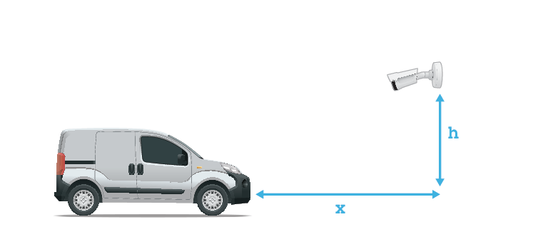
When you select the mounting location, remember that direct sunlight can distort the image, for example, during sunrise and sunset.
The mounting height for a camera in a Access control scenario should be half of the distance of that between the vehicle and the camera.
The mounting height for camera in a Free flow (slow traffic license plate recognition) scenario should be less than half of the distance of that between the vehicle and the camera.
Access control capture distance: 2–7 m (6.6–23 ft). This example is based on the AXIS P3265–LVE-3 License Plate Verifier kit.
Capture distance: (C)
Mounting height (A)
2.0 m (6.6 ft)
1.0 m (3.3 ft)
3.0 m (9.8 ft)
1.5 m (4.9 ft)
4.0 m (13 ft)
2.0 m (6.6 ft)
5.0 m (16 ft)
2.5 m (8.2 ft)
7.0 m (23 ft)
3.5 m (11 ft)
Free flow capture distance: 7–20m (23–65 ft). This example is based on the AXIS P1465–LE-3 License Plate Verifier kit.
Capture distance (C)
Mounting height (A)
7.0 m (23 ft)
3.0 m (9.8 ft)
10.0 m (33 ft)
4.0 m (13 ft)
15.0 m (49 ft)
6.0 m (19.5 ft)
20.0 m (65 ft)
10.0 m (33 ft)
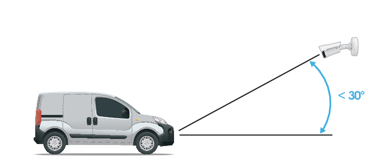
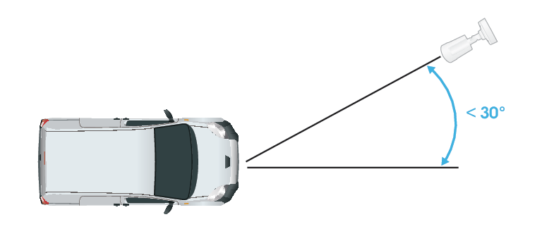
The camera’s mounting angle should not be larger than 30° in any direction.
Mounting angle from the side.
Mounting angle from above.
The image of the license plate should not tilt more than 5° horizontally. If the image is tilted more than 5°, we recommended that you adjust the camera so that the license plate is displayed horizontally in the live stream.
Roll angle.
Setup assistant
When you first run the application, set up Free flow or Access control using the setup assistant. If you want to make changes later on, go to Settings > Maintenance and under Setup assistant press Start.
Free flow
In Free flow, the application can detect and read license plates in slow speed traffic on larger access roads, city centers and enclosed areas like campuses, ports or airports. This allows for LPR-forensic search and LPR triggered events in a VMS.
Select Free flow and click Next.
Select the image rotation that corresponds to how your camera is mounted.
Select the number of areas of interest. Note that one area can detect plates in both directions.
Select the region where the camera is located.
Select capture type.
License plate crop saves only the license plate.
Vehicle crop saves the entire captured vehicle.
Frame downsized 480x270 saves the entire image and reduces the resolution to 480x270.
Full frame saves the entire image at full resolution.
Adjust the direction of the area of interest. Click the arrow and rotate to set the direction. The direction determines how the application registers vehicles entering or exiting the area.
Click Next
In the Protocol drop-down list, select one of the following protocols:
TCP
HTTP POST
In the Server URL field, type the server address and port in the following format: 127.0.0.1:8080
In the Device ID field, type the name of the device or leave as is.
Under Event types, select one or more of the following options:
New means the first detection of a license plate.
Update is either a correction of a character on a previously detected license plate, or when a a direction is detected as the plate moves and is tracked across the image.
Lost is the last tracked event of the license plate before it exits the image. It also contains the direction of the license plate.
To turn on the feature, select Send event data to server.
To reduce bandwidth when using HTTP POST, you can select Do not to send images through HTTP POST.
Click Next.
If you already have a list of registered plates, choose to import as either a blocklist or allowlist.
Click Finish.
Access control
Use the setup wizard for quick and easy configuration. You can choose to Skip to leave the guide at any time.
In the Protocol drop-down list, select one of the following protocols:
TCP
HTTP POST
In the Server URL field, type the server address and port in the following format: 127.0.0.1:8080.
In the Device ID field, type the name of the device or leave as is.
Under Event types, select one or more of the following options:
New means the first detection of a license plate.
Update is either a correction of a character on a previously detected license plate, or when a a direction is detected as the plate moves and is tracked across the image.
Lost is the last tracked event of the license plate before it exits the image. It also contains the direction of the license plate.
To turn on the feature, select Send event data to server.
To reduce bandwidth when using HTTP POST, you can select Do not to send images through HTTP POST.
Click Next
On the Import list from a .csv file page:
If you already have a list of registered plates, choose to import as either a blocklist or allowlist.
Click Finish.
Access the application settings
In the camera’s web interface, go to Apps, start the application and click Open.
Adjust the area of interest
The area of interest is the area in the live view where the application looks for license plates. For optimal performance, keep the area of interest as small as possible. To adjust the area of interest, do the following:
Go to Settings.
Click Image.
Click on 1:1 to zoom in where you want monitor traffic or manage access control.
To improve verification and captured images, click on AF.
To have the camera automatically focus on the vehicles, click AF. To set the focus manually, adjust it with the slider.
Click on Area of interest to see it displayed in the view area.
To move the area of interest, click anywhere in the area to select it and drag it to where the license plates are most visible. Make sure the region of interest stays in position after you have saved the settings.
To adjust the area of interest, click anywhere in the area to select it and drag the anchor points highlighted in blue.
To reset the area of interest, click on the reset button on the lower left corner next to the number icon.
To add anchor points, click the on one of the dark anchor points. The anchor point will turn yellow, showing it can be manipulated. New dark points are automatically added next to the yellow anchor point. The maximum amount of yellow anchor points is eight.
Click anywhere outside the area of interest to save your changes.
To get the correct direction feedback in the Event log, you need to turn the arrow to match the driving direction.
Click the arrow icon.
Select the anchor point and rotate the arrow so it aligns with the driving direction.
Click outside the area of interest to save the changes.
Note that one area can detect plates in both directions. The direction feedback shows up in the Direction column.
To check if your area of interest is large enough for the best results, use the pixel counter.
To show the pixel counter, click on the calculator icon.
To adjust the full size pixel counter area, drag the lower right corner of the area highlighted in yellow.
To move the pixel counter area, click anywhere in the area and drag it where you want.
To add a second area of interest, click on + next to 1.
If you are using a standalone camera, you can have the app set the recommended settings for license plate recognition.
Click on the magic wand icon and the settings will be optimized for license plate recognition.
Click on the menu button next to the magic wand to see the set values.
Select region
Go to Settings > Recognition.
In the Region drop-down list, select your region.
Adjust the image capture settings
Go to Settings > Image.
To change the resolution of captured images, go to Image resolution
To change the rotation of the captured image, go to Rotation
Set up event storage
An event consists of the captured image, the license plate, the area of interest number, vehicle direction, access, and the date and time.
This example use case explains how to store events of allowlisted license plate numbers for 30 days.
Requirements:
Camera physically installed and connected to the network.
AXIS License Plate Verifier up and running on the camera.
Internal storage or an SD card installed in the camera.
Go to Settings > Storage.
Under Retain events, select Allowlisted.
Under Retention period, select 30 days.
To change how you save your captured images, go to Save full frame:
License plate crop saves only the license plate.
Vehicle crop saves the entire captured vehicle.
Frame downsized 480x270 saves the entire image and reduces the resolution to 480x270.
Full frame saves the entire image at full resolution.
Note
To detect an inserted SD card when the app is running, you need to restart the app. If an SD card is installed in the camera, the app will automatically choose the SD card as the default storage. AXIS License Plate Verifier uses the cameras internal memory to save up to 1,000 events, using license plate crops as the frame. If you use larger frames, it will vary the amount of events you can save. An SD card can save up to 100,000 events using any type of frame.
Installation
Preview mode
Preview mode is ideal for installers when fine tuning the camera view during the installation. No login is required to access the camera view in preview mode. It is available only in factory defaulted state for a limited time from powering up the device.
This video demonstrates how to use preview mode.
Configure your device
For users of AXIS Camera Station
Set up AXIS License Plate Verifier
When a device is configured with AXIS License Plate Verifier, it is considered as an external data source in the video management system. You can connect a view to the data source, search for the license plates that are captured by the device, and view the related image.
Note
It requires AXIS Camera Station 5.38 or later.
AXIS License Plate Verifier requires a license.
Download and install the application on your device.
Search for license plates that are captured by the device. See Data search.
Click to export the search results to a .txt file.
Basic settings
Set the mounting position
Go to Video > Installation > Mounting position.
Click Change.
Select a mounting position and click Save and restart.
Set the power line frequency
Go to Video > Installation > Power line frequency.
Select a power line frequency and click Save and restart.
Adjust the image
This section includes instructions about configuring your device.
Reduce image processing time with low latency mode
You can optimize the image processing time of your live stream by turning on low latency mode. The latency in your live stream is reduced to a minimum. When you use low latency mode, the image quality is lower than usual.
Go to System > Plain config.
Select ImageSource from the drop-down list.
Go to ImageSource/I0/Sensor > Low latency mode and select On.
Click Save.
Select exposure mode
To improve image quality for specific surveillance scenes, use exposure modes. Exposure modes lets you control aperture, shutter speed, and gain. Go to Video > Image > Exposure and select between the following exposure modes:
For most use cases, select Automatic exposure.
For environments with certain artificial lighting, for example fluorescent lighting, select Flicker-free.
Select the same frequency as the power line frequency.
For environments with certain artificial light and bright light, for example outdoors with fluorescent lighting at night and sun during daytime, select Flicker-reduced.
Select the same frequency as the power line frequency.
To lock the current exposure settings, select Hold current.
Compensate for barrel distortion
Barrel distortion is a phenomenon where straight lines appear increasingly bent closer to the edges of the frame. A wide field of view often creates barrel distortion in an image. Barrel distortion correction compensates for this distortion.
Note
Barrel distortion correction affects the image resolution and field of view.
Go to Video > Installation > Image correction.
Turn on Barrel distortion correction (BDC).
Verify the pixel resolution
To verify that a defined part of the image contains enough pixels to, for example, recognize license plates, you can use the pixel counter.
Go to Video > Image.
Click .
Click for Pixel counter.
In the camera’s live view, adjust the size and position of the rectangle around the area of interest, for example where you expect license plates to appear.
You can see the number of pixels for each of the rectangle’s sides, and decide if the values are enough for your needs.
View and record video
This section includes instructions about configuring your device. To learn more about how streaming and storage works, go to .
Reduce bandwidth and storage
Important
Reducing the bandwidth can lead to loss of detail in the image.
Go to Video > Stream.
Click in the live view.
Select Video format AV1 if your device supports it. Otherwise select H.264.
Go to Video > Stream > General and increase Compression.
Go to Video > Stream > Zipstream and do one or more of the following:
Note
The Zipstream settings are used for all video encodings except MJPEG.
Select the Zipstream Strength that you want to use.
Turn on Optimize for storage. This can only be used if the video management software supports B-frames.
Turn on Dynamic FPS.
Turn on Dynamic GOP and set a high Upper limit GOP length value.
Note
Most web browsers don’t support H.265 decoding and because of this the device doesn’t support it in its web interface. Instead you can use a video management system or application that supports H.265 decoding.
Set up network storage
To store recordings on the network, you need to set up your network storage.
Go to System > Storage.
Click Add network storage under Network storage.
Type the IP address of the host server.
Type the name of the shared location on the host server under Network share.
Type the username and password.
Select the SMB version or leave it on Auto.
Select Add share without testing if you experience temporary connection issues, or if the share is not yet configured.
Click Add.
Record and watch video
Record video directly from the camera
Go to Video > Stream.
To start a recording, click .
If you haven’t set up any storage, click and . For instructions on how to set up network storage, see Set up network storage
To stop recording, click again.
Watch video
Go to Recordings.
Click for your recording in the list.
Verify that no one has tampered with the video
With signed video, you can make sure that no one has tampered with the video recorded by the camera.
Go to Video > Stream > General and turn on Signed video.
Record video directly on the device, or use AXIS Camera Station Pro or another compatible video management software. For AXIS Camera Station Pro instructions, see the AXIS Camera Station Pro user manual.
You can create rules to make your device perform an action when certain events occur. A rule consists of conditions and actions. The conditions can be used to trigger the actions. For example, the device can start a recording or send an email when it detects motion, or show an overlay text while the device is recording.
Record video when the camera detects a license plate
This example explains how to set up the camera to start recording to the SD card when the camera detects an object. The recording will include five seconds before detection and one minute after detection ends.
Before you start:
Make sure you have an SD card installed.
Make sure that AXIS Licence Plate Verifier is running:
Go to Apps > AXIS License Plate Verifier.
Start the application if it is not already running.
Make sure you have set up the application according to your needs.
Create a rule:
Go to System > Events and add a rule.
Type a name for the rule.
In the list of conditions, under Application, select ALPV.PlateInView.
In the list of actions, under Recordings, select Record video while the rule is active.
In the list of storage options, select SD_DISK.
Select a camera and a stream profile.
Set the prebuffer time to 5 seconds.
Set the postbuffer time to 1 minute.
Click Save.
Trigger a notification when the camera lens is tampered
This example explains how to set up an email notification when the camera lens gets either spray painted, covered, or blurred.
Activate the tampering detection:
Go to System > Detectors > Camera tampering.
Set a value for Trigger delay. The value indicates the time that must pass before an email is sent.
Turn on Trigger on dark images to detect if the lens is sprayed, covered, or rendered severely out of focus.
Add an email recipient:
Go to System > Events > Recipients and add a recipient.
Type a name for the recipient.
Select Email as the notification type.
Type the recipient’s email address.
Type the email address that you want the camera to send notifications from.
Provide the login details for the sending email account, along with the SMTP hostname and port number.
To test your email setup, click Test.
Click Save.
Create a rule:
Go to System > Events > Rules and add a rule.
Type a name for the rule.
In the list of conditions, under Video, select Tampering.
In the list of actions, under Notifications, select Send notification to email and then select the recipient from the list.
Type a subject line and message for the email.
Click Save.
Audio
Add audio to your recording
Turn on audio:
Go to Video > Stream > Audio and include audio.
If the device has more than one input source, select the correct one in Source.
Go to Audio > Device settings and turn on the correct input source.
Edit the stream profile that is used for the recording:
Go to System > Stream profiles and select the stream profile.
Select Include audio and turn it on.
Click Save.
Add audio capability to your product using portcast
With portcast technology, you can add audio capability to your product. It allows audio and I/O communication digitally over the network cable between the camera and the interface.
To add audio capability to your Axis network video device, connect the portcast compatible Axis audio device and I/O Interface between your device and the PoE switch which provides power.
Connect the Axis network video device (1) and the Axis portcast device (2) with a PoE cable.
Connect the Axis portcast device (2) and the PoE switch (3) with a PoE cable.
Axis network video device
Axis portcast device
Switch
Once the devices are connected, an audio tab becomes visible in the settings for your Axis network video device. Go to the audio tab and turn on Allow audio.
See your Axis portcast device’s user manual for more information.
Manage lists
Add detected license plate to list
A license plate can be added directly to a list after being detected by the application.
Click on Home.
Go to Live.
Click on the arrow icon on the registered plate in the list.
Click on Append plate to list.
Select the list you would like to add the license plate in the dialog.
Click Append.
Note
Make sure the symbols <,> and & aren’t used in either the license plate or description.
Add descriptions to license plates
To add a description to a license plate in the list:
Go to List management.
Select the license plate and click then select Edit in the drop-down menu.
Type the relevant information in the Description field.
Click Save.
Note
Make sure the symbols <,> and & aren’t used in either license plates or descriptions.
Customize list names
You can change the name of any of the lists to fit your specific use case.
Go to List management.
Click next to the list you want to change.
Select Edit.
Type the name of the list.
Click Submit.
The new list name will be updated in any existing configurations.
Import allowlisted license plate numbers
You can import allowlisted license plate numbers from a .csv file on the computer. In addition to the license plate number, you can also add comments for each license plate number in the .csv file.
The structure of the .csv file must look like this: license plate,date,description
Example
Only license plate: AXIS123
License plate + description: AXIS123,,John Smith
License plate + date + description: AXIS123,2022-06-08,John Smith
Note
Make sure the symbols <,> and & aren’t used in either license plates or descriptions.
Go to List management
Click on next to Allowlist and select Import in the drop-down menu.
Browse to select a .csv file on the computer.
Click OK.
Check that the imported license plate numbers appear in the Allowlist.
Share license plate lists with other cameras
You can share the license plate lists with other cameras on the network. The synchronization will override all current license plate lists in the other cameras.
Go to List management > List synchronization.
Under Remote connected devices, type the IP address, username and password.
Click Add.
Click Synchronize list.
Check that the date and time under Last sync updates accordingly.
Schedule lists
Lists can be scheduled to only be active during certain times during certain days of the week. To schedule a list:
Go to List management.
Click next to the list you want to change.
Select Schedule in the drop-down menu.
Select the start and end time, and the day when the list should be active.
Click the button next to Enabled.
Click Save.
Additional settings
Configure text overlay
A text overlay shows the following event information in the live view: weekday, month, time, year, license plate number.
Go to Settings > Image.
Activate Text overlay.
Select either Timestamp and license plate or License plate only.
Set Overlay duration to a value between 1 and 9 seconds.
Check that the overlay appears in the live view.
Detect license plates in low-light conditions
Each detection gets a score by the algorithm, this is called the confidence threshold. Detections that have a lower score than the selected level will not show up in the list of events.
For scenes with low lighting you can set a lower confidence threshold, which will allow for detection of more plates.
Go to Settings > Recognition.
Adjust the slider under Confidence threshold.
Check that the algorithm detects the license plates as expected.
Allow fewer characters on license plates
The application has a default minimum number of characters for a license plate to be detected. The default minimum number of characters is five. You can configure the application to detect license plates with fewer characters.
Go to Settings > Recognition.
Under Number of characters, adjust the slider to set the minimum number of characters you want to allow.
Check that the application detects license plates as expected.
Allow only exact matches of license plates
The matching algorithm automatically allows a deviation of one character when matching the detected license plate against the allowlist or blocklist. However, some scenarios need an exact match of all characters of the license plate.
Go to List management.
Click to activate Strict matching.
Check that the application matches the license plates as expected.
Allow more than one character deviation when matching license plates
The matching algorithm automatically allows a deviation of one character when matching the detected license plate against the allowlist or blocklist. However, you can allow more than one character deviation.
Go to Settings > Recognition.
Under Allowed character deviation, select the number of characters that are allowed to be different.
Check that the application matches the license plates as expected.
Give limited access to operators
Operators can be given a limited access to the app using an URL. This way they only have access to the Event log and List management. The URL can be found under Settings > User rights.
Set up secure connection
To protect communication and data between devices, for example between the camera and the door controller, set up a secure connection with HTTPS using certificates.
Go to Settings > Security.
Under HTTPS, select either Self-signed or CA-signed.
You can backup and restore settings made in the app related to image capture, security, detection and integration. If something should go wrong, you can now restore the settings you have backed up.
To backup app settings:
Go to Settings > Maintenance.
Click Download backup configuration.
A JSON file will be downloaded to you downloads folder.
To restore app settings:
Go to Settings > Maintenance.
Click Restore configuration.
Select the JSON file containing the backup.
The setting are restored automatically.
Clear all events
After you set up the app, it can be a good idea to clear the records of any images or captured plates from the setup process.
To clear all images and plates from the database:
Go to Settings > Maintenance.
Click Clear all recognition results.
Click Yes.
Use virtual ports to trigger actions
Virtual ports can be used together with access control to trigger any kind of action. This example explains how to set up AXIS License Plate Verifier together with the camera’s I/O port to display a text overlay using a virtual port.
Requirements:
Camera physically installed and connected to the network.
AXIS License Plate Verifier up and running on the camera.
Cables connected between the barrier and the camera’s I/O port.
Basic setup done. See .
Go to the application’s webpage and select the Settings tab.
Go to Access control.
Under Access control, select Internal I/O.
Select the I/O output #.
Select a port in the Virtual port drop-down list.
Under Barrier mode, select Open to all.
Under Vehicle direction, select Any.
Select the Area of interest you would like to use.
In the camera’s webpage, go to System > Events.
Click Add rule.
Under Condition select Virtual input is active and the port number you have selected.
Under Action, select Use overlay text.
Select Video channels.
Type the text you want displayed.
Add the duration of the text.
Click Save.
Go to Video > Overlays.
Go to Overlays.
Select Text in the drop-down menu and click +.
Type #D or select the modifier in the Modifiers drop-down list.
Check that the text overlay is displayed when a vehicle enters the region of interest in the live view.
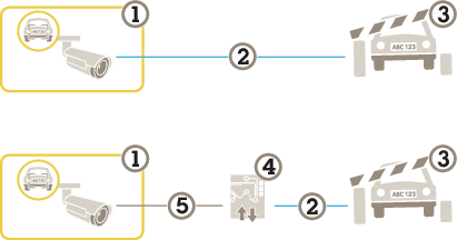
Vehicle entry and exit scenario
In the scenario for vehicle entry and exit, the application reads the vehicle license plate captured by the camera and verifies the license plate against a list of authorized or unauthorized license plate numbers stored in the camera.
This scenario requires the application embedded in a camera with I/O support or a connected I/O relay module to open and close the barrier.
Two possible setups for the vehicle entry and exit scenario.
Axis camera with AXIS License Plate Verifier
I/O communication
Barrier
Axis I/O relay module
IP communication
Open a barrier for known vehicles using a relay module
This example use case explains how to set up AXIS License Plate Verifier together with a relay module to open a barrier for a known vehicle driving through a specific region of interest (ROI) into, let’s say a parking area.
Requirements:
Camera physically installed and connected to the network.
AXIS License Plate Verifier up and running on the camera.
Cables connected between the barrier and the relay module.
Go to the camera’s webpage, select Settings and open AXIS License Plate Verifier.
Go to the relay module’s webpage and make sure the relay port is connected to the camera’s I/O port.
Copy the relay module’s IP address.
Go back to AXIS License Plate Verifier.
Go to Settings>Access control.
Go to Type and select Relay in the drop-down list.
In the I/O output drop-down list, select the I/O port that is connected to the barrier.
In the Barrier mode drop-down list, select Open from lists and then check Allowlist.
In the Vehicle direction drop-down list, select in.
In the ROI drop-down list, select the area of interest that covers the traffic lane.
Enter the following information:
the IP address for the relay module in format 192.168.0.0
the username for the relay module
the password for the relay module
To make sure the connection works, click Connect.
To activate the connection, click Turn on integration.
Go to the List management tab
Enter the license plate number in the Allowlist field.
Note
The physical input ports 1 to 8 on the relay module correspond to ports 1 to 8 in the drop-down list. However, the relay ports 1 to 8 on the relay module correspond to ports 9 to 16 in the drop-down list. This is valid even if the relay module only has 8 ports.
Check that the application identifies the license plate number in the allowlist as a known vehicle and that the barrier opens as expected.
Open a barrier for known vehicles using the camera's I/O
This example explains how to set up AXIS License Plate Verifier together with the camera’s I/O port to open a barrier for a known vehicle entering, for example, a parking area.
Requirements:
Camera physically installed and connected to the network.
AXIS License Plate Verifier up and running on the camera.
Cables connected between the barrier and the camera’s I/O port.
Enter the license plate number in the Blocklist field.
Go to the camera’s webpage.
Go to Settings > Events and set up an action rule with the application as a condition and with a notification as an action.
Check that the application identifies the added license plate number as an unauthorized vehicle and that the action rule runs as expected.
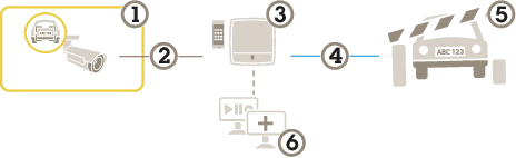
Vehicle access control scenario
In the scenario for vehicle access control, the application can be connected to an Axis network door controller to configure access rules, create schedules for access times, and handle vehicle access not only for employees, but also, for example, visitors and suppliers.
For backup, use an access system involving a door controller and card reader. To set up the door controller and the card reader, see the user documentation at axis.com
Axis camera with AXIS License Plate Verifier
IP communication
Axis network door controller with card reader
I/O communication
Barrier
Optional third-party software
Connect to a door controller
In this example we connect the camera to a network door controller which means the camera works as a sensor. The camera forwards the information to the controller which in turn analyzes the information and triggers the events.
Note
When switching between the AXIS License Plate Verifier and AXIS Entry Manager, make sure to refresh the webpages to get access to all parameters.
Requirements:
Camera and door controller physically installed and connected to the network.
AXIS License Plate Verifier up and running on the camera.
How to get the application up and running with AXIS A1001 Door Controller.
Hardware configuration in AXIS Entry Manager
Go to AXIS Entry Manager and start a new hardware configuration under Setup.
In the hardware configuration, rename the network door controller to “Gate controller”.
Click Next.
In Configure locks connected to this controller, clear the Door monitor option.
Click Next.
In Configure readers connected to this controller, clear the Exit reader option.
Click Finish.
Configuration in AXIS License Plate Verifier
Go the AXIS License Plate Verifier webpage.
Go to the Settings>Access control.
Go to Type and select Controller in the drop-down list.
Enter the following information:
the IP address for the controller in format 192.168.0.0
the username for the controller
the password for the controller
Click Connect.
If the connection is successful, “Gatecontroller” shows up in the Network Door Controller name drop-down list. Select “Gatecontroller”.
In the Reader name drop-down list, select the reader connected to the door “Gatecontroller”, for example “Reader entrance”. These names can be changed in AXIS Entry Manager.
To activate the connection, select Turn on integration.
Enter one of the user’s license plate number, or use the default, in the test field and click Test integration. Check that the test was successful.
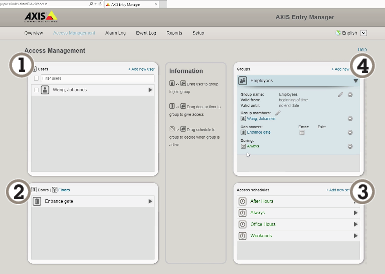
Configure users, groups, doors, and schedules in AXIS Entry Manager
Go to AXIS Entry Manager.
Go to Access Management.
Go to Doors > Add identification type.
In the Credentials needed drop-down list, select License plate only.
To set limits for when the identification type can be used, drag and drop a Schedule to the door.
Add users and, for each user, add the credential License plate.
Click Add credential again and enter the license plate information.
Click Add new group and enter the information.
To add users to a group, drag and drop Users to the user group.
To give users access, drag and drop the Door to the user group.
To limit the access time, drag and drop a Schedule to the user group.
Overview of AXIS Entry Manager user interface.
Users
Doors
Schedules
User groups
Connect to AXIS Secure Entry
This example describes connecting an Axis door controller in AXIS Camera Station and AXIS Secure Entry with AXIS Licence Plate Verifier.
Requirements:
Camera and door controller physically installed and connected to the network.
AXIS License Plate Verifier up and running on the camera.
AXIS Camera Station client version 5.49.449 and up.
In a free flow scenario with speed measurement, the camera is paired with an Axis radar through the edge-to-edge technology. The camera covers two lanes and reads the license plates of the passing vehicles, and the paired radar covers the same two lanes to measure the speed of the vehicles. Additionally, the application AXIS Speed Monitor can visualize the maximum speed in each lane through overlays in the camera's live view.
An Axis license plate verifier camera kit and AXIS D2210-VE Radar installed and connected to the network
Set up the scenario
Set up the scenario in four steps: first configure the camera, then pair and configure the radar, and finally use AXIS Speed Monitor to add overlays.
Before you start:
Make sure that the camera and radar are directed towards the same area of interest.
Make sure that the camera and radar are time synced. To check the status, go to Installation > Time sync status in each device.
Make sure that the camera’s second view area (View area 2) isn’t used, since the radar will use it after pairing.
Configure the camera:
Set up the camera according to the instructions in Basic setup.
Make sure to select free flow when you follow the setup assistant. For more information, see Free flow.
Pair the camera with a radar:
In the camera’s web interface, go to System > Edge-to-edge > Radar pairing.
Enter the host name, user name, and password of the radar.
Click Connect to pair the devices.
When the connection is established, the radar settings will be available in the camera’s web interface.
Note
The default resolution of the paired radar is 1280x720. Keep the default resolution of the radar in the camera’s web interface, and if you add it to a VMS.
Configure the radar:
In the camera’s web interface, go to Radar > Scenarios.
Add one radar scenario that covers one lane, and another radar scenario that covers the other lane.
For both scenarios, select Movement in area, trigger on Vehicles, and set a Speed limit.
For more information, go to Add scenarios in AXIS D2210-VE Radar user manual.
Note
If you want to add overlays containing license plate information through AXIS License Plate Verifier, make sure to add these before you add any overlays in AXIS Speed Monitor.
Use AXIS Speed Monitor to add speed overlays:
Download and install AXIS Speed Monitor on your camera.
Add one overlay for each lane, which will show the maximum speed in the camera’s live view.
Use the search feature to search for events using a number of criteria.
Go to the application’s webpage and select the Search page.
Select the date in the From and To calendar menus.
Click the AOI drop down menu to select which area of interest should be included in the search.
select Direction to filter by entry or exit.
Enter the license plate in the Plate field, if you want to search for a plate.
To find license plates that belong to a specific country, select a country in the Country drop-down list..
To filter out images based on the view of the vehicle, select Front or Rear in the Vehicle view drop-down list.
To filter the search results based on the make, model, type or color of the vehicle, select what you are looking for in the Vehicle details drop-down menus.
Click Apply filters to view the search results.
Export and share search results
To export any search result as a CSV file with the statistics at that time, click Export to save the results as a CSV file
To copy the API as a link which can be used to export data to third party systems, click Copy search link.
Integration
Use profiles to push events to multiple servers
With profiles, you can push an event to different servers using different protocols at the same time. To use profiles:
With this feature you can integrate third-party software by pushing the event data through TCP or HTTP POST.
Before you start:
The camera must be physically installed and connected to the network.
AXIS License Plate Verifier must up and running on the camera.
Go to Integration > Push events.
Select an empty profile
In the Protocol drop-down list, select HTTP POST.
In the Server URL field, type the server address and port in the following format: 127.0.0.1:8080
Type the user name and password.
If you are using a proxy, turn the proxy on and type the hostname, username and password.
In the Device ID field, type the name of the device or leave as is.
Select which direction to trigger push events under Push conditions.
Under LPR Event types, select one or more of the following options:
New means the first detection of a license plate.
Update is either a correction of a character on a previously detected license plate, or when a a direction is detected as the plate moves and is tracked across the image.
Lost is the last tracked event of the license plate before it exits the image. It also contains the direction of the license plate.
Conditional pushes one event for one object when conditions are met.
To reduce bandwidth when using HTTP POST, you can select Do not to send images.
Enable Event buffer to buffer events if the server goes down, and send them when the server becomes available.
To include the license plate crop in addition to the image if you’ve chosen under Retention settings select Send two images.
To send the events in mulitpart format instead of base64, select Multipart.
Click Test to test the integration with a virtual license plate.
To turn on the feature, select Activate.
Note
To push events using HTTP POST, you can use an authorization header instead of a user name and password, go to Auth-Header , and add a path to an authentication API.
Send images of license plates to a server
With this feature you can push images of the license plates to a server through FTP.
Before you start:
The camera must be physically installed and connected to the network.
AXIS License Plate Verifier must up and running on the camera.
Go to Integration > Push events.
In the Protocol drop-down list, select FTP.
In the Server URL field, type the server address in the following format: ftp://10.21.65.77/LPR.
Type the username and password for the FTP server.
Select the path and name modifiers for the filenames.
In the Device ID field, type the name of the device. A folder with this name will be created for the images. Images are created using the following format: timestamp_area of interest_direction_carID_license plate text_country.jpg.
Select which direction to trigger push events under Push conditions.
Under Event types, select one or more of the following options:
New means the first detection of a license plate.
Update is either a correction of a character on a previously detected license plate, or when a a direction is detected as the plate moves and is tracked across the image.
Lost is the last tracked event of the license plate before it exits the image. It also contains the direction of the license plate.
Conditional pushes one event for one object when conditions are met.
Note
Direction is only included in the filename when Lost or Update is selected.
Click Test to test the integration with a virtual license plate.
If push events fail, the app will resend up to the first 100 failed events to the server. When using FTP in push events to a Windows server, do not use %c for naming of images that gives you date and time. This is due to the fact that Windows does not accept the naming set by the function %c for date and time. Note that this is not an issue when using a Linux server.
Direct integration with 2N
This example describes direct integration with a 2N IP device.
Set up an account in your 2N device:
Go to 2N IP Verso.
Go to Services > HTTP API > Account 1.
Select Enable account.
Select Camera access.
Select License plate recognition.
Copy the IP address.
In the AXIS License Plate Verifier app:
Go to Integration > Direct integration.
Select 2N IP Device.
Add the IP address or URL to the 2N device.
Type your username and password.
Select Connection type.
Select what the Barrier is used for.
Click Enable integration.
Select the direction of the vehicles..
To turn on the feature, select Activate.
To check in the integration is working:
Go to 2N IP Verso.
Go to Status > Events.
Integrate with Genetec Security Center
This example describes setting up a direct integration with Genetec Security Center.
In Genetec Security Center:
Go to Overview.
Make sure that Database, Directory and License are online. If they’re not, run all Genetec and SQLEXPRESS services in Windows.
Go to Genetec Config Tool > Plugins.
Click Add an entity.
Go to Plugin and select LPR plugin.
Click Next.
Click Next.
Click Next.
Select the LPR plugin you’ve added and go to Data sources .
Under ALPR reads API:
Check Enabled.
In Name, type: Plugin REST API.
In API path prefix, type: lpr.
In REST port, select 443.
In WebSDK host, type: localhost.
In WebSDK port, select 443.
Check Allow self signed certificates.
Under Security Center events data source:
Check Enabled.
In Name, type Security Center Lpr Events.
In Processing frequency, select 5 sec in the drop-down menu.
Go to the Data sinks tab.
Click +.
In Type, select Database.
Select and configure the database:.
Check Enabled.
In Source, check Plugin REST API and Native ALPR Events.
In Name, type Reads DB.
In Include, check Reads, Hits and Images.
Go to the Resources tab.
Click Delete the database and then Create a database.
Create an API user:
Go to Config Tool > User Management.
Click Add an entity.
Select User.
Type a username and password. Leave the other fields unchanged.
Select the added user and go to the Privileges tab.
Check to allow everything under Application privileges.
Check to allow Third-party ALPR reads API.
Click Apply.
In the AXIS License Plate Verifier app:
Go to Integration>Direct integration.
Select Genetec Security Center.
In URL/IP, type your address according to this template: https://server-address/api/V1/lpr/lpringestion/reads.
Type in your Genetec username and password.
Select Connection type.
To turn on the feature, select Activate.
Click Test to test the integration with a virtual license plate.
If you’ve chosen HTTPS, go to the Settings tab.
Under Security > HTTPS.
Select Self-signed, or CA-signed depending on the settings in Genetec Security Center.
To read about all the features and settings available in the web interface of devices with AXIS OS, go to AXIS OS web interface help.
Learn more
Edge-to-edge technology
Edge-to-edge is a technology that makes IP devices communicate directly with each other. It offers smart pairing functionality between, for example, Axis cameras and Axis audio or radar products.
Note
Make sure the paired devices run the same AXIS OS version.
With edge-to-edge radar pairing, you can connect your camera to a compatible Axis radar and benefit from integrated radar features, such as speed detection.
Radar pairing is a one-way setup where you pair one camera with one radar and use the camera to configure and maintain both devices. When paired, you can access the radar's settings and create rules for radar-specific events directly in the camera's web interface. The camera will also identify itself to a VMS as a camera with integrated radar functionality.
Additionally, the radar stream is visualized in the camera’s second view area, called view area 2. The metadata produced by the radar is available through the camera’s second metadata producer channel, called channel 2.
Speaker pairing
Edge-to-edge speaker pairing allows you to use a compatible Axis network speaker as if it’s part of your camera. Once paired, the speaker's features are integrated in the camera's web interface and the network speaker acts as an audio out device where you can play audio clips and transmit sound through the camera.
The camera will identify itself to the VMS as a camera with integrated audio output and redirect any played audio to the speaker.
View area
A view area is a cropped part of the full view. You can stream and store view areas instead of the full view to minimize bandwidth and storage needs. If you enable PTZ for a view area, you can pan, tilt and zoom within it. By using view areas you can remove parts of the full view, for example, the sky.
When you set up a view area, we recommend you to set the video stream resolution to the same size as or smaller than the view area size. If you set the video stream resolution larger than the view area size it implies digitally scaled up video after sensor capture, which requires more bandwidth without adding image information.
Note
If you pair the camera with a radar through edge-to-edge, the radar stream is visualized in the camera’s second view area.
AXIS Image Health Analytics
AXIS Image Health Analytics is an AI-based application that can be used to detect image degradations or tampering attempts. The application analyzes and learns the behavior of the scene to detect blurriness or underexposure in the image, or to detect an obstructed or redirected view. You can set up the application to send events for any of these detections, and trigger actions through the camera’s event system or third-party software.
Shows steady green for 10 seconds for normal operation after startup completed.
Amber
Steady during startup. Flashes during device software upgrade or reset to factory default.
Amber/Red
Flashes amber/red if network connection is unavailable or lost.
SD card slot
NOTICE
Risk of damage to SD card. Don’t use sharp tools, metal objects, or excessive force when inserting or removing the SD card. Use your fingers to insert and remove the card.
Risk of data loss and corrupted recordings. Unmount the SD card from the device’s web interface before removing it. Don’t remove the SD card while the product is running.
This device supports microSD/microSDHC/microSDXC cards.
microSD, microSDHC, and microSDXC Logos are trademarks of SD-3C LLC. microSD, microSDHC, microSDXC are trademarks or registered trademarks of SD-3C, LLC in the United States, other countries or both.
RJ45 Ethernet connector with Power over Ethernet (PoE).
Audio connector
4-pin terminal block for audio input and output.
Function
Pin
Notes
GND
1
Ground
Ring power
2
12 V for external source
Microphone/Line in
3
Microphone (analog or digital) or line in (mono). 5 V microphone bias is available.
Line out
4
Line level audio output (mono). Can be connected to a public address (PA) system or an active speaker with a built-in amplifier.
I/O connector
Use the I/O connector with external devices in combination with, for example, motion detection, event triggering, and alarm notifications. In addition to the 0 VDC reference point and power (12 V DC output), the I/O connector provides the interface to:
Digital input
For connecting devices that can toggle between an open and closed circuit, for example PIR sensors, door/window contacts, and glass break detectors.
Supervised input
Enables possibility to detect tampering on a digital input.
Digital output
For connecting external devices such as relays and LEDs. Connected devices can be activated by the VAPIX® Application Programming Interface, through an event or from the device’s web interface.
4-pin terminal block
Function
Pin
Notes
Specifications
DC ground
1
0 VDC
DC output
2
Can be used to power auxiliary equipment. Note: This pin can only be used as power out.
12 VDC Max load = 25 mA
Digital Input or Supervised Input
3
Connect to pin 1 to activate, or leave floating (unconnected) to deactivate. To use supervised input, install end-of-line resistors. See connection diagram for information about how to connect the resistors.
0 to max 30 VDC
Digital Output
4
Internally connected to pin 1 (DC ground) when active, and floating (unconnected) when inactive. If used with an inductive load, e.g., a relay, connect a diode in parallel with the load, to protect against voltage transients.
0 to max 30 VDC, open drain, 100 mA
Example
DC ground
DC output 12 V, max 25 mA
Supervised input
Digital output
Troubleshooting
Reset to factory default settings
WARNING
Possibly hazardous optical radiation is emitted from this product. It can be harmful to the eyes. Do not stare at the operating lamp.
Important
Reset to factory default should be used with caution. A reset to factory default resets all settings, including the IP address, to the factory default values.
Note
The camera has been preconfigured with AXIS License Plate Verifier. If you reset to factory default, you will keep the license key. You will not need to reinstall the application after a factory reset.
To reset the product to the factory default settings:
Disconnect power from the product.
Press and hold the control button while reconnecting power. See Product overview.
Keep the control button pressed for 15–30 seconds until the status LED indicator flashes amber.
Release the control button. The process is complete when the status LED indicator turns green. The product has been reset to the factory default settings. If no DHCP server is available on the network, the default IP address is 192.168.0.90.
Use the installation and management software tools to assign an IP address, set the password, and access the device.
The installation and management software tools are available from the support pages on axis.com/support.
You can also reset parameters to factory default through the device’s webpage. Go to Maintenance > Factory default and click Default.
AXIS OS options
Axis offers device software management according to either the active track or the long-term support (LTS) tracks. Being on the active track means continuously getting access to all the latest product features, while the LTS tracks provide a fixed platform with periodic releases focused mainly on bug fixes and security updates.
Using AXIS OS from the active track is recommended if you want to access the newest features, or if you use Axis end-to-end system offerings. The LTS tracks are recommended if you use third-party integrations, which are not continuously validated against the latest active track. With LTS, the products can maintain cybersecurity without introducing any significant functional changes or affecting any existing integrations. For more detailed information about Axis device software strategy, go to axis.com/support/device-software.
Check the current AXIS OS version
AXIS OS determines the functionality of our devices. When you troubleshoot a problem, we recommend that you to start by checking the current AXIS OS version. The latest version might contain a correction that fixes your particular problem.
To check the current AXIS OS version:
Go to the device’s web interface > Status.
Under Device info, see the AXIS OS version.
Upgrade AXIS OS
Important
When you upgrade the device software, your preconfigured and customized settings are saved. Axis Communications AB can't guarantee that the settings are saved, even if the features are available in the new AXIS OS version.
Starting from AXIS OS 12.6, you must install every LTS version between your device’s current version and the target version. For example, if the currently installed device software version is AXIS OS 11.2, you have to install the LTS version AXIS OS 11.11 before you can upgrade the device to AXIS OS 12.6. For more information, see AXIS OS Lifecycle guide: Upgrade path.
Make sure the device remains connected to the power source throughout the upgrade process.
Note
When you upgrade the device with the latest AXIS OS version in the active track, the product receives the latest functionality available. Always read the upgrade instructions and release notes available with each new release before you upgrade. To find the latest AXIS OS version and the release notes, go to axis.com/support/device-software.
If the upgrade fails, the device reloads the previous version. The most common reason is that the wrong AXIS OS file has been uploaded. Check that the name of the AXIS OS file corresponds to your device and try again.
Problems after AXIS OS upgrade
If you experience problems after the upgrade, roll back to the previously installed version from the Maintenance page.
Problems setting the IP address
Can’t set the IP address
If the IP address intended for the device and the IP address of the computer used to access the device are located on different subnets, you can’t set the IP address. Contact your network administrator to obtain an IP address.
The IP address could be in use by another device. To check:
Disconnect the Axis device from the network.
In a Command/DOS window, type ping and the IP address of the device.
If you receive: Reply from <IP address>: bytes=32; time=10... this means that the IP address might already be in use by another device on the network. Obtain a new IP address from the network administrator and reinstall the device.
If you receive: Request timed out, this means that the IP address is available for use with the Axis device. Check all cabling and reinstall the device.
There could be a possible IP address conflict with another device on the same subnet. The static IP address in the Axis device is used before the DHCP server sets a dynamic address. This means that if the same default static IP address is also used by another device, there could be problems accessing the device.
Problems accessing the device
Can’t log in when accessing the device from a browser
When HTTPS is enabled, make sure that you use the correct protocol (HTTP or HTTPS) when you try to log in. You might need to manually type http or https in the browser’s address field.
If you’ve lost the password for the root account, you must reset the device to the factory default settings. For instructions, see Reset to factory default settings.
The IP address has been changed by DHCP
IP addresses obtained from a DHCP server are dynamic and could change. If the IP address has been changed, use AXIS IP Utility or AXIS Device Manager to locate the device on the network. Identify the device using its model or serial number, or by the DNS name (if the name has been configured).
If required, you can assign a static IP address manually. For instructions, go to axis.com/support.
Certificate error when using IEEE 802.1X
For authentication to work properly, the date and time settings in the Axis device must be synchronized with an NTP server. Go to System > Date and time.
To access the device externally, we recommend you to use one of the following applications for Windows®:
AXIS Camera Station Edge: free of charge, ideal for small systems with basic surveillance needs.
AXIS Camera Station Pro: 90-day trial version free of charge, ideal for small to mid-size systems.
For instructions and download, go to axis.com/vms.
Problems with streaming
Multicast H.264 only accessible by local clients
Check if your router supports multicasting, or if you need to configure the router settings between the client and the device. You might need to increase the TTL (Time To Live) value.
No multicast H.264 displayed in the client
Check with your network administrator that the multicast addresses used by the Axis device are valid for your network.
Check with your network administrator to see if there is a firewall that prevents viewing.
Poor rendering of H.264 images
Ensure that your graphics card uses the latest driver. You can usually download the latest drivers from the manufacturer’s website.
Color saturation is different in H.264 and Motion JPEG
Modify the settings for your graphics adapter. Check the adapter’s documentation for more information.
Reduce the number of applications running on the client computer.
Limit the number of simultaneous viewers.
Check with the network administrator that there is enough bandwidth available.
Lower the image resolution.
Log in to the device’s web interface and set a capture mode that prioritizes frame rate. If you change the capture mode to prioritize frame rate it might lower the maximum resolution, depending on the device used and capture modes available.
Can't select H.265 encoding in live view
Web browsers don’t support H.265 decoding. Use a video management system or application that supports H.265 decoding.
Problems with MQTT
Can’t connect over port 8883 with MQTT over SSL
The firewall blocks traffic that uses port 8883 since it’s regarded insecure.
In some cases the server/broker might not provide a specific port for MQTT communication. It might still be possible to use MQTT over a port normally used for HTTP/HTTPS traffic.
If the server/broker supports WebSocket/WebSocket Secure (WS/WSS), typically on port 443, use this protocol instead. Check with the server/broker provider to see if WS/WSS is supported and which port and basepath to use.
If the server/broker supports ALPN, the use of MQTT can be negotiated over an open port, such as 443. Check with your server/broker provider to see if ALPN is supported and which ALPN protocol and port to use.
If you can’t find what you’re looking for here, try the troubleshooting section at axis.com/support.
Unknown vehicles are marked as accepted
If the application lets in vehicles with license plates that are not in the allowlist, one probable reason is that the comparison allows a deviation of one character. For example, if AXI S1234 is in the allowlist the application accepts AXI SI234. Similarly, if AXIS 1234 is in the allowlist the application accepts AXI 1234.
The connection between the application and controller or relay module doesn’t work
Make sure the controller, or relay module, allows data traffic through HTTP. To find out how to change this setting, go to the user manual for the corresponding device.
Problems with radar pairing
I can’t pair the camera with the radar
Make sure the camera’s second view area (View area 2) isn’t used since the radar will be assigned to this automatically.
If the second view area is used, go to Video > View areas to remove it, and then try to pair the devices again.
The moving vehicles in the camera view are not in sync with the speed overlays, or with the tracks in the radar view
Make sure the camera and radar are time synced.
To check the status, go to Status > Time sync status in the web interface of each device. If the status shows Synchronized: No, click on NTP settings and select a time source for synchronizing the device. Make sure to use the same time source for both devices.
The camera’s second view area doesn’t show the radar stream correctly
The default resolution of the radar after edge-to-edge pairing is 1280x720, both in the camera’s web interface and in a VMS. If you select another resolution, the radar stream will appear incorrectly.
To adjust the resolution of the radar, go to Video > Stream > General in the camera’s web interface and select View area 2.
Problems with overlays
The overlays I have added through the camera’s web interface disappear after radar pairing
If you have added more than one view area in the camera, any previously added overlays will disappear from the camera’s web interface. Since the radar will occupy the second view area after radar pairing, all existing overlays in the camera’s web interface will disappear.
The overlays will only disappear from the web interface. You can still request a stream containing the overlays, for example in a VMS.
The license plate overlays I have added in AXIS License Plate Verifier don’t appear
If you have added overlays that show the vehicle speed in AXIS Speed Monitor, and then turn on license plate overlays in AXIS License Plate Verifier, the license plate overlays won’t appear.
Make sure to turn on the overlays in AXIS License Plate Verifier first, before you add any speed overlays through AXIS Speed Monitor.
Performance considerations
When you set up your system, it’s important to consider how different settings and situations affect performance. Some factors affect bandwidth (bitrate), others affect frame rate, and some affect both.
The most important factors to consider:
High image resolution or lower compression levels result in images containing more data which in turn affects the bandwidth.
Rotating the image in the GUI can increase the product's CPU load.
Access by large numbers of Motion JPEG clients or unicast H.264/H.265/AV1 clients affects the bandwidth.
Simultaneous viewing of different streams (resolution, compression) by different clients affects both frame rate and bandwidth.
Use identical streams wherever possible to maintain a high frame rate. Stream profiles can be used to ensure that streams are identical.
Accessing video streams with different codecs simultaneously affects both frame rate and bandwidth. For optimal performance, use streams with the same codec.
Heavy usage of event settings affects the product’s CPU load which in turn affects the frame rate.
Using HTTPS may reduce frame rate, in particular if streaming Motion JPEG.
Heavy network utilization due to poor infrastructure affects the bandwidth.
Viewing on poorly performing client computers lowers perceived performance and affects frame rate.
Running multiple AXIS Camera Application Platform (ACAP) applications simultaneously may affect the frame rate and the general performance.
Cybersecurity supports a successful product lifecycle with minimized risks. You can find in-depth information and documentation about our cybersecurity approach at axis.com/about-axis/cybersecurity. Follow the cybersecurity guidelines below to receive product security notifications from Axis and to configure your product for a secure lifecycle and decommissioning.
At Axis Trust Center, you can find information about how Axis implements security compliance, transparency, data protection, and privacy.
Subscribe to Axis security notification emails at axis.com/security-notification-service. We will send you information about vulnerabilities, corresponding security advisories, and other security-related matters for your Axis product.
Secure product lifecycle
Axis minimizes risks throughout the lifetime of our products through secure lifecycle management. Use our hardening guides at help.axis.com to more securely configure and operate your Axis products and to find information about:
Secure first-use
Axis products are pre-configured with high default protection to allow for secure initialization and encrypted communication from the very start.
Intended use and common configuration mistakes
Our guides provide information about the intended usage of Axis products, including common security-relevant misuse and configuration mistakes that should be avoided.
Managing vulnerabilities and supply chain transparency
A Software Bill of Material (SBOM) is published with every software release on axis.com to disclose vulnerabilities and improve supply chain transparency.
Decommissioning and the secure erasure of data
To securely decommission a product when it reaches the end of its lifecycle, reset it to factory default settings. This erases your configurations, stored data, and sensitive information.

 to export the search results to a .txt file.
 then select Edit in the drop-down menu.