
AXIS P1486-LE Kit License Plate Verifier
インストール
プレビューモード
プレビューモードは、設置担当者が設置中にカメラビューを微調整する際に最適です。プレビューモードでは、カメラビューにアクセスするのにログインする必要はありません。このモードは、装置の電源投入から一定時間、工場出荷時の設定状態でのみ使用できます。
使用に当たって
ネットワーク上のデバイスを検索する
Windows®で検索したAxisデバイスにIPアドレスの割り当てを行うには、AXIS IP UtilityまたはAXIS Device Managerを使用します。いずれのアプリケーションも無料で、axis.com/supportからダウンロードできます。
IPアドレスの検索や割り当てを行う方法の詳細については、IPアドレスの割り当てとデバイスへのアクセス⽅法を参照してください。
ブラウザーサポート
以下のブラウザーでデバイスを使用できます。
ChromeTM | EdgeTM | Firefox® | Safari® | |
Windows® | ✓ | ✓ | * | * |
macOS® | ✓ | ✓ | * | * |
Linux® | ✓ | ✓ | * | * |
その他のオペレーティングシステム | * | * | * | * |
✓:推奨
*:制限付きでサポート
装置のwebインターフェースを開く
ブラウザーを開き、Axis装置のIPアドレスまたはホスト名を入力します。
本製品のIPアドレスが不明な場合は、AXIS IPUtilityまたはAXIS DeviceManagerを使用して、ネットワーク上のデバイスを検索してください。
ユーザー名とパスワードを入力します。装置に初めてアクセスする場合は、管理者アカウントを作成する必要があります。管理者アカウントを作成します。を参照してください。
AXIS OS搭載デバイスのWebインターフェースにおけるすべての機能および設定の説明については、AXIS OS Webインターフェースヘルプを参照してください。
管理者アカウントを作成します。
装置に初めてログインするときには、管理者アカウントを作成する必要があります。
アカウントを入力します。
パスワードを入力します。安全なパスワードを参照してください。
パスワードを再入力します。
使用許諾契約書に同意します。
[ Add account (アカウントを追加)] をクリックします。
装置にはデフォルトのアカウントはありません。管理者アカウントのパスワードを紛失した場合は、装置をリセットする必要があります。工場出荷時の設定にリセットします。を参照してください。
安全なパスワード
ネットワーク経由でパスワードやその他の機密性の高い設定を行う際は、HTTPS (デフォルトで有効) を使用してください。HTTPSは、安全で暗号化されたネットワーク接続を可能にし、パスワードなどのセンシティブなデータを保護します。
デバイスのパスワードは主にデータおよびサービスを保護します。Axisデバイスは、さまざまなタイプのインストールで使用できるようにするためパスワードポリシーを強制しません。
データを保護するために、次のことが強く推奨されています。
8文字以上のパスワードを使用する (できればパスワード生成プログラムで作成する)。
パスワードを公開しない。
一定の期間ごとにパスワードを変更する (少なくとも年に1回)。
デバイスのソフトウェアが改ざんされていないことを確認する
- 装置に元のAXIS OSが搭載されていることを確認するか、またはセキュリティ攻撃が行われた後に装置を完全に制御するには、以下の手順に従います。
工場出荷時の設定にリセットします。工場出荷時の設定にリセットします。を参照してください。
リセットを行うと、セキュアブートによって装置の状態が保証されます。
デバイスを設定し、インストールします。
基本設定
以下の設定手順は、すべてのシナリオで有効です。
カメラ取り付けの推奨事項
設置場所を選択するときは、日の出や日の入りの間などに、直射日光が画像に影響を及ぼす可能性があることに注意してください。
[Access control (アクセスコントロール)] シナリオでのカメラの取り付け高さは、車両とカメラとの間の距離の半分にする必要があります。
[Free flow (フリーフロー)] (低速走行車両のナンバープレート認識) シナリオでのカメラの取り付け高さは、車両とカメラとの間の距離の半分未満にする必要があります。
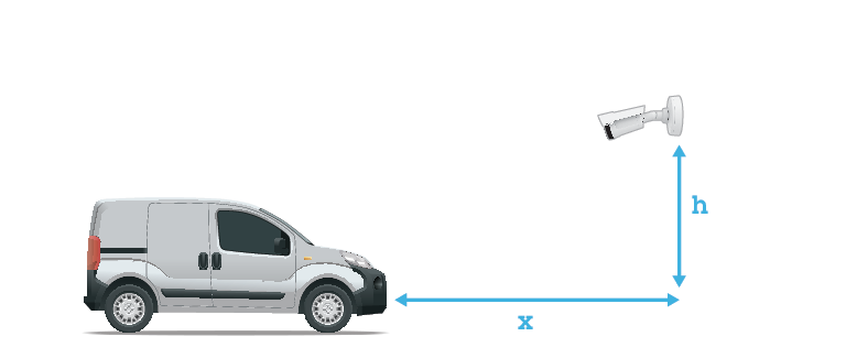
- アクセスコントロール キャプチャー距離: 2~7 m (6.6~23 ft)。この例は、AXIS P3265-LVE-3 License Plate Verifier Kitに基づいています。
キャプチャー距離: (C) 取り付け高さ (A) 2.0 m (6.6 ft) 1.0 m (3.3 ft) 3.0 m (9.8 ft) 1.5 m (4.9 ft) 4.0 m (13 ft) 2.0 m (6.6 ft) 5.0 m (16 ft) 2.5 m (8.2 ft) 7.0 m (23 ft) 3.5 m (11 ft) - フリーフロー キャプチャー距離: 7~20m(23~65 ft)。この例は、AXIS P1465-LE-3 License Plate Verifier Kitに基づいています。
キャプチャー距離 (C) 取り付け高さ (A) 7.0 m (23 ft) 3.0 m (9.8 ft) 10.0 m (33 ft) 4.0 m (13 ft) 15.0 m (49 ft) 6.0 m (19.5 ft) 20.0 m (65 ft) 10.0 m (33 ft) カメラの取り付け角度は、いずれの方向でも30°より大きくしないでください。
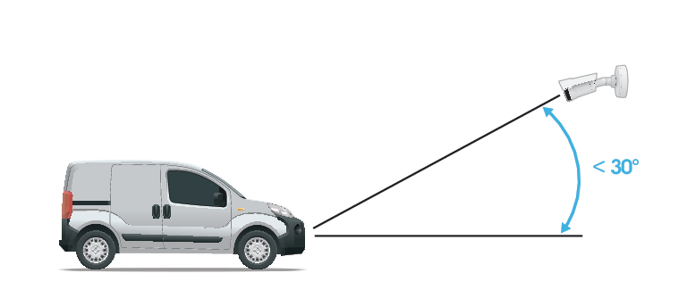
横からの取り付け角度。 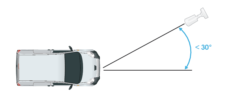
上からの取り付け角度。 ナンバープレートの画像は、水平方向に5°を超えてチルトさせないでください。画像が5°を超えてチルトしている場合は、ライブストリームでナンバープレートが水平に表示されるように、カメラを調整することをお勧めします。
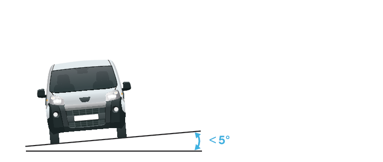
ロール角度。
設定アシスタント
アプリケーションを最初に実行するときは、設定アシスタントを使用して [Free flow (フリーフロー)] または [Access control (アクセスコントロール)] を設定します。後で変更する場合は、 [Settings (設定)] > [Maintenance (メンテナンス)] に移動し、[Setup assistant (設定アシスタント)] で [Start(開始)] を押します。
フリーフロー
フリーフローでは、このアプリケーションは大規模な連絡道路、市街地のほか、キャンパス、港、空港などの閉鎖されたエリアで、低速走行車両のナンバープレートを検知して読み取ることができます。これにより、VMSでLPRフォレンジック検索やLPRトリガーイベントが可能になります。
[Free flow (フリーフロー)] を選択し、[Next (次へ)] をクリックします。
カメラの取り付け方法に応じて画像の回転を選択します。
対象範囲の数を選択します。1つの範囲で、両方向でプレートを検知できることに注意してください。
カメラが配置されている範囲を選択します。
キャプチャータイプを選択します。
License plate crop (ナンバープレートのクロップ): ナンバープレートのみが保存されます。
Vehicle crop (車両のクロップ): キャプチャーされた車両全体が保存されます。
Frame downsized 480x270 (480x270にダウンサイズされたフレーム): 画像全体が保存され、解像度は480x270に下げられます。
Full frame (フルフレーム): 画像全体がフル解像度で保存されます。
アンカーポイントをドラッグして、対象範囲を調整します。対象範囲を調整するを参照してください。
対象範囲の方向を調整します。矢印をクリックして回転させて、方向を設定します。方向により、対象範囲に出入りする車両がアプリケーションで登録される方法が決まります。
[Next (次へ)] をクリックします。
[Protocol (プロトコル)] ドロップダウンリストで、以下のいずれかのプロトコルを選択します。
TCP
HTTP POST
[Server URL (サーバーのURL)] フィールドに、次の形式でサーバーのアドレスとポートを入力します:
127.0.0.1:8080[Device ID (デバイスID)] フィールドに装置の名前を入力するか、そのままにします。
[Event types (イベントタイプ)] で、以下のオプションから1つ以上選択します。
[New (新規)] は、ナンバープレートが初めて検知されたことを意味します。
[Update (更新)] は、以前に検知されたナンバープレートの文字を修正する場合と、プレートの移動に伴って方向が検知され、画像上で追跡される場合のどちらかです。
[Lost (消失)] は、ナンバープレートが画像から出る前の最後の追跡イベントです。これには、ナンバープレートの方向も含まれます。
この機能をオンにするには、[Send event data to server (イベントデータをサーバーに送信する)] を選択します。
HTTP POSTを使用する際に帯域幅を削減するには、[Do not to send images through HTTP POST (HTTP POST で画像を送信しない)] を選択します。
[Next (次へ)] をクリックします。
登録済みのプレートのリストがすでにある場合は、[blocklist (ブロックリスト)] としてインポートするか、[allowlist (許可リスト)] としてインポートするかを選択します。
Finish (終了) をクリックします。
アクセスコントロール
セットアップウィザードを使用すると、すばやく簡単に設定できます。[Skip (スキップ)] を選択して、いつでもガイドを読み飛ばすことができます。
[Access control (アクセスコントロール)] を選択し、[Next (次へ)] をクリックします。
使用するアクセスコントロールのタイプを選択します。
カメラでリストを管理する場合は、[Internal I/O (内部I/O)] を選択します。既知の車両の場合に、カメラのI/Oを使用してゲートを開くを参照してください。
ドアコントローラーを接続する場合は、[Controller (コントローラー)] を選択します。ドアコントローラーに接続するを参照してください。
リレーモジュールに接続する場合は、[Relay (リレー)] を選択します。既知の車両の場合に、リレーモジュールを使用してゲートを開くを参照してください。
[Barrier mode (ゲートモード)] ドロップダウンリストの [Open from lists (リストから開く)] で、[Allowlist (許可リスト)] を選択します。
[Vehicle direction] (車両の方向) ドロップダウンリストから [out] (出庫) を選択します。
[ROI] ドロップダウンリストで、使用する対象範囲を選択するか、すべての対象範囲を使用するかを選択します。
[Next (次へ)] をクリックします。
[Image settings (画像設定)] ページで、次の設定を行います。
対象範囲の数を選択します。
カメラが配置されている範囲を選択します。
キャプチャータイプを選択します。画像キャプチャーの設定を調整するを参照してください。
アンカーポイントをドラッグして、対象範囲を調整します。対象範囲を調整するを参照してください。
対象範囲の方向を調整します。方向により、対象範囲に出入りする車両がアプリケーションで登録される方法が決まります。
[Next (次へ)] をクリックします。
[Event data (イベントデータ)] ページ で、次の処理を行います。
詳細な設定については、サードパーティ製ソフトウェアへのイベント情報のプッシュを参照してください。
[Protocol (プロトコル)] ドロップダウンリストで、以下のいずれかのプロトコルを選択します。
TCP
HTTP POST
[Server URL (サーバーのURL)] フィールドに、次の形式でサーバーのアドレスとポートを入力します:
127.0.0.1:8080。[Device ID (デバイスID)] フィールドに装置の名前を入力するか、そのままにします。
[Event types (イベントタイプ)] で、以下のオプションから1つ以上選択します。
[New (新規)] は、ナンバープレートが初めて検知されたことを意味します。
[Update (更新)] は、以前に検知されたナンバープレートの文字を修正する場合と、プレートの移動に伴って方向が検知され、画像上で追跡される場合のどちらかです。
[Lost (消失)] は、ナンバープレートが画像から出る前の最後の追跡イベントです。これには、ナンバープレートの方向も含まれます。
この機能をオンにするには、[Send event data to server (イベントデータをサーバーに送信する)] を選択します。
HTTP POSTを使用する際に帯域幅を削減するには、[Do not to send images through HTTP POST (HTTP POST で画像を送信しない)] を選択します。
[Next (次へ)] をクリックします。
- [Import list from a .csv file (.csvファイルからリストをインポート)] ページで、次の操作を行います。
登録済みのプレートのリストがすでにある場合は、[blocklist (ブロックリスト)] としてインポートするか、[allowlist (許可リスト)] としてインポートするかを選択します。
Finish (終了) をクリックします。
アプリケーションの設定にアクセスする
カメラのwebインターフェースで、[Apps (アプリ)] に移動し、アプリケーションを起動して、[Open (開く)] をクリックします。
対象範囲を調整する
対象範囲は、アプリケーションがナンバープレートを探すライブビュー内のエリアです。最適なパフォーマンスを得るには、対象範囲をできるだけ小さく保ってください。対象範囲を調整するには、以下の手順に従います。
[Settings (設定)] に移動します。
[Image (画像)] をクリックします。
1:1をクリックすると、監視したい場所やアクセスコントロールを管理したい場所をズームできます。
検証とキャプチャー画像の品質を高めるには、[AF] をクリックします。
車両に自動でフォーカスを合わせるには、[AF]をクリックします。手動でフォーカスを合わせる場合は、スライダーで調整します。
[Area of interest (対象範囲)] をクリックして、ビューエリアに表示します。
対象範囲を移動するには、その範囲内の任意の場所をクリックして選択し、ナンバープレートが最も見えやすい場所にドラッグします。設定を保存した後、対象範囲が適切な位置にとどまっていることを確認してください。
対象範囲を調整するには、範囲内の任意の場所をクリックして選択し、青色で強調表示されているアンカーポイントをドラッグします。
対象範囲をリセットするには、左下の数字アイコンの横のリセットボタンをクリックします。
アンカーポイントを追加するには、暗色のアンカーポイントのいずれかをクリックします。アンカーポイントが黄色に変わり、操作できることを示します。黄色のアンカーポイントの隣に新しい暗色のポイントが自動的に追加されます。黄色のアンカーポイントの最大数は8です。
対象範囲の外部のどこかをクリックすると、変更が保存されます。
[Event log (イベントログ)] で正しい方向のフィードバックを取得するには、矢印を運転方向に向ける必要があります。
矢印アイコンをクリックします。
アンカーポイントを選択し、矢印を回転させて、運転方向に合わせます。
対象範囲の外部でクリックすると、変更が保存されます。
- 1つの範囲で、両方向でプレートを検知できることに注意してください。方向のフィードバックは、[Direction] (方向) 列に表示されます。
対象範囲が最適な効果を得るために十分な大きさかどうかを確認するには、ピクセルカウンターを使用します。
ピクセルカウンターを表示するには、電卓のアイコンをクリックします。
フルサイズのピクセルカウンターエリアを調整するには、黄色でハイライト表示されているエリアの右下のコーナーをドラッグします。
ピクセルカウンターエリアを移動するには、そのエリア内の任意の場所をクリックし、移動先にドラッグします。
2つ目の対象範囲を追加するには、1の横の+をクリックします。
スタンドアロンのカメラを使用している場合は、アプリでナンバープレート認識の推奨設定を適用できます。
魔法の杖のアイコンをクリックすると、ナンバープレート認識用に設定が最適化されます。
魔法の杖の横にあるメニューボタンをクリックすると、設定値が表示されます。
地域の選択
[Settings (設定)] > [Recognition (認識)] に移動します。
[Region (地域)] ドロップダウンリストから地域を選択します。
画像キャプチャーの設定を調整する
[Settings (設定)] > [Image (画像)] に移動します。
キャプチャーされた画像の解像度を変更するには、[Image resolution (画像解像度)] に移動します。
キャプチャーされた画像の回転を変更するには、[Rotation (回転)] に移動します。
イベントストレージを設定する
イベントは、キャプチャーした画像、ナンバープレート、関心領域番号、車の方向、アクセス、日付と時刻で構成されます。
この使用事例では、許可リストに追加されたナンバープレート番号のイベントを30日間、保存する方法について説明します。
- 要件:
カメラがネットワークに物理的に設置および接続されている。
カメラでAXIS License Plate Verifierが起動され実行されている。
内部ストレージまたはカメラに取り付けられたSDカード。
[Settings (設定)] > [Storage (ストレージ)] に移動します。
[Retain events (イベントの保持)] で、[Allowlisted (許可リスト)] を選択します。
[Retention period (保持期間)] で、[30 days (30日)] を選択します。
キャプチャーされた画像の保存方法を変更するには、[Save full frame (フルフレームを保存)] に移動します。
License plate crop (ナンバープレートのクロップ): ナンバープレートのみが保存されます。
Vehicle crop (車両のクロップ): キャプチャーされた車両全体が保存されます。
Frame downsized 480x270 (480x270にダウンサイズされたフレーム): 画像全体が保存され、解像度は480x270に下げられます。
Full frame (フルフレーム): 画像全体がフル解像度で保存されます。
- 注
アプリの実行中に挿入されたSDカードを検知するには、アプリを再起動する必要があります。カメラにSDカードが取り付けられている場合、デフォルトストレージとしてSDカードが自動的に選択されます。
AXIS License Plate Verifierは、カメラの内部メモリを利用して、ナンバープレートのクロップをフレームとして使って最大1,000件のイベントを保存します。大型のフレームを使用する場合、保存できるイベントの量が変わります。
SDカードは、任意のタイプのフレームを使用して最大100,000件のイベントを保存できます。
デバイスを構成する
このセクションでは、ハードウェアのインストールが完了した後に製品を起動して実行するために、設置者が行う必要のあるすべての重要な設定について説明しています。
AXIS Camera Stationのユーザー向け
AXIS License Plate Verifierの設定
装置がAXIS License Plate Verifierで設定されている場合、その装置はビデオ管理システムの外部データソースと見なされます。表示をデータソースに接続し、装置でキャプチャーされたナンバープレートを検索して関連する画像を表示できます。
基本設定
キャプチャーモードを設定する
[Video (ビデオ)] > [Installation (インストール)] > [Capture mode (キャプチャーモード)] に移動します。
[Change (変更)] をクリックします。
キャプチャーモードを選択し、[Save and restart (保存して再起動する)] をクリックします。
キャプチャーモードも参照してください。
取り付け位置を設定する
[Video (ビデオ)] >「Installation (インストール)] > [Mounting position (取り付け位置)] に移動します。
[Change (変更)] をクリックします。
取り付け位置を選択し、[Save and restart (保存して再起動)] をクリックします。
電源周波数を設定する
[Video (ビデオ)] > [Installation (インストール)] > [Power line frequency (電源周波数)] に移動します。
電源周波数を選択し、[Save and restart (保存して再起動)] をクリックします。
Set the orientation (向きを設定する)
[Video > Installation > Rotate (ビデオ > インストール > 回転)] に移動します。
[Auto (自動)]、[0]、[90]、[180] または [270]度を選択します。
細長いエリアを監視するも参照してください。
画像を調整する
このセクションでは、デバイスの設定について説明します。特定の機能の詳細については、詳細情報を参照してください。
カメラを水平にする
- 参照エリアまたは物体との関係で表示を調整するには、レベルグリッドとカメラの機械的な調整を組み合わせて使用します。
[Video (ビデオ)] > [Image (画像)] > の順に移動して、 をクリックします。
をクリックすると、レベルグリッドが表示されます。
参照エリアまたは物体の位置がレベルグリッドと揃うまで、カメラを機械的に調整します。
ズームとフォーカスを調整します。
- ズームの調整方法:
[Video > Installation (ビデオ > インストール)] に移動し、ズームスライダーを調整します。
- フォーカスの調整方法:
をクリックすると、オートフォーカスエリアが表示されます。
画像内でフォーカスを合わせる部分が収まるように、オートフォーカスエリアを調整します。
オートフォーカスエリアを選択しない場合、エリア全体にカメラのフォーカスが合わせられます。静的な物体にフォーカスを合わせることをお勧めします。
[Autofocus] (オートフォーカス) をクリックします。
フォーカスを微調整するには、フォーカススライダーを調整します。
低遅延モードで画像処理時間を短縮する
低遅延モードをオンにすることで、ライブストリームの画像処理時間を最適化できます。ライブストリームの遅延が最小限に短縮されます。低遅延モードを使用すると、通常より画質が低下します。
[System > Plain config (システム > プレイン設定)] に移動します。
ドロップダウンリストから [ImageSource (画像ソース)] を選択します。
[ImageSource/I0/Sensor > Low latency mode (画像ソース/I0/センサー > 低遅延モード)] に移動し、[On (オン)] を選択します。
[Save (保存)] をクリックします。
露出モードを選択する
監視カメラのシーンに合わせて画質を向上させるには、露出モードを使用します。露出モードでは、開口、シャッター、ゲインを制御できます。[Video (ビデオ) > Image (画像) > Exposure (露出)] に移動し、以下の露出モードから選択します。
ほとんどの用途では、[Automatic (自動)] 露出を選択します。
蛍光灯など、特定の人工照明がある環境では、[Flicker-free (ちらつき防止)] を選択します。
電源周波数と同じ周波数を選択します。
蛍光灯照明がある夜間の屋外や太陽光が射す日中の屋外など、特定の人工照明や明るい光がある環境では、[Flicker-reduced (ちらつき低減)] を選択します。
電源周波数と同じ周波数を選択します。
現在の露出設定を固定するには、[Hold current (現在の状態で固定)] を選択します。
ナイトモードを使用して低光量下で赤外線照明からメリットを得る
日中、カメラは可視光を利用してカラー画像を提供します。しかし、可視光線が薄くなると、色の画像は明るく鮮明になります。この場合、ナイトモードに切り替えた場合、カメラは可視光と近赤外線の両方の光を使用して、代わりに明るい画像と詳細な白黒画像を提供します。カメラが自動的にナイトモードに切り替わります。
[Video (ビデオ)] > [Night mode (ナイトモード)] に移動し、モードが [Auto (自動)].に設定されていることを確認します。
カメラがナイトモードのときに内蔵の赤外線照明を使用するには、[Internal IR controls (内部IRコントロール)] に移動し、Allow IR (IRを許可)] をオンにします。
赤外線設定
Synchronize illumination (照明の同期): 内蔵照明がデイナイトモードに同期します。カメラがナイトモードに切り替わるとオンになり、デイモードに切り替わるとオフになります。
Automatic illumination angle (自動照明角度): 有効にすると、現在のズーム設定に基づいて個々のLEDの明るさが視野に合わせて調整されます。
ストロボ同期: 無効にすると、内蔵照明が連続点灯 (常時点灯) します。有効にすると、内蔵照明がストロボ発光し、各フラッシュはフレームに同期されます。これにより、連続光に比べて、短い露出時間でより高いピーク出力を得ることができます。最大シャッタースピードが1/100秒を超える場合は、ストロボの同期設定を [Off (オフ)] (デフォルト) に設定することをお勧めします。より短いシャッタースピード (例: 1/1000秒) を使用する場合は、ストロボの同期の設定を[On (オン)]に切り替えることをお勧めします。
赤外線照明を最適化する
シーン内の外部光源など、設置環境やカメラの周囲の条件によっては、LEDの強度を手動で設定すると画質が改善される場合があります。LEDからの反射に問題がある場合は、強度を下げてみてください。
[Video (ビデオ)] > [Night mode (ナイトモード)] > [Internal IR controls (内部IRコントロール)] に移動します。
[Allow IR (IRを許可)] をオンにします。
ライブビューで をクリックし、[Manual (手動)] を選択します。
強度を調整します。
低照度環境でノイズを減らす
低照度の条件下でノイズを少なくするために、以下のうち1つ以上の設定ができます。
ノイズと動きによる画像のブレの間のトレードオフを調整します。[Settings > Image > Exposure (設定 > 画像 > 露出)] に移動し、[Blur-noise trade-off (ブレとノイズのトレードオフ)] スライダーを [Low noise (低ノイズ)] の方に動かします。
[露出モード] を [自動] に設定します。
- 注
最大シャッター値が高いと、動きによる画像のブレが生じる場合があります。
シャッター速度を遅くするには、最大シャッターをできるだけ大きな値に設定します。
- 注
最大ゲインを下げると、画像が暗くなる場合があります。
最大ゲインをより低い値に設定します。
[Aperture (開口)] スライダーがある場合は、スライダーを [Open (開く)] の方向に向かって動かします。
[Video (ビデオ)] > [Image (画像)] > [Appearance (外観)] で、画像のシャープネスを下げます。
低光量下で動きによる画像のブレを減らす
- 低光量の条件下で画像のブレを少なくするために、[Video (ビデオ) > Image (画像) > Exposure (露出)] で次の1つ以上の設定を調整することができます。
- 注
ゲインを大きくすると、画像のノイズが多くなります。
[Max shutter (最大シャッター)] を短い時間に設定し、[Max gain (最大ゲイン)] をより高い値に設定します。
- それでも動きによる画像のブレに問題がある場合は、
シーン内の光源レベルを上げます。
物体が横向きではなく、カメラの方へ移動するか、カメラから離れるように移動するようにカメラを取り付けます。
逆光の強いシーンを処理する
ダイナミックレンジとは、画像内の明るさのレベルの差のことです。最も暗い部分と最も明るい部分の差がかなり大きい場合があります。その場合、暗い部分か明るい部分の画像だけが見えることがよくあります。ワイドダイナミックレンジ (WDR) を使用すると、画像の暗い部分と明るい部分の両方が見えるようになります。
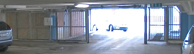
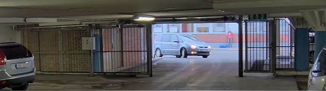
- WDRを使用すると、画像にノイズが発生することがあります。
- WDRは、一部のキャプチャーモードでは使用できない場合があります。
[Settings > Image > Wide dynamic range (設定 > 画像 > ワイドダイナミックレンジ)] に移動します。
WDR をオンにします。
[Local contrast (ローカルコントラスト)] スライダーを使用して、WDRの量を調整します。
[Tone mapping (トーンマッピング)] スライダーを使用して、WDRの量を調整します。
それでも問題が発生する場合は、[Exposure (露出)] に移動して [Exposure zone (露出エリア)] を調整し、対象範囲をカバーします。
WDRとその使用方法の詳細については、axis.com/web-articles/wdrをご覧ください。
たる型歪曲の補正
バレル歪曲 (たる型歪曲) とは、フレームの端に近づくにつれて、直線の曲がりが現れる現象です。広い視野では、多くの場合、画像内にバレル歪曲が発生します。バレル歪曲補正では、この歪曲が補正されます。
バレル歪曲補正は、画像の解像度と視野に影響します。
[Video (ビデオ)] > [Installation (インストール)] > [Image correction (画像補正)] に移動します。
[Barrel distortion correction (BDC) (バレル歪曲補正 (BDC)) ] をオンにします。
細長いエリアを監視する
階段、廊下、道路またはトンネルなどの細長いエリアにおける視野をすべてよりよく活用するためには、Corridor Formatを使用します。
デバイスによって、カメラまたはカメラの3軸レンズの向きを90°または270°回転します。
装置がビューの自動回転を行わない場合は、[Video (ビデオ) > Installation (インストール)] に移動します。
視野を90°または270°回転させます。
ピクセル解像度の確認
画像の定義された部分に、ナンバープレートなどを認識するのに十分なピクセルが含まれていることを確認するには、ピクセルカウンターを使用します。
[Video > Image (ビデオ > 画像)] に移動します。
をクリックします。
ピクセルカウンターのをクリックします。
カメラのライブビューで、ナンバープレートが表示されると予想される位置など、対象範囲の四角形のサイズおよび位置を調整します。
四角形の各辺 (XとY) のピクセル数が表示され、値がニーズを満たすのに十分かどうかを決定することができます。
プライバシーマスクで画像の一部を非表示にする
1つ以上のプライバシーマスクを作成して、画像の一部を隠すことができます。
[Video (ビデオ) > Privacy masks (プライバシーマスク)] に移動します。
をクリックします。
新しいマスクをクリックし、名前を入力します。
必要に応じて、プライバシーマスクのサイズと位置を調整します。
すべてのプライバシーマスクの色を変更するには、[Privacy masks (プライバシーマスク)] をクリックし、色を選択します。
プライバシーマスク も参照してください。
画像オーバーレイを表示する
ビデオストリームのオーバーレイとして画像を追加することができます。
[Video (ビデオ)] > [Overlays (オーバーレイ)] に移動します。
画像管理をクリックします。
画像をアップロードするか、画像をドラッグアンドドロップします。
[Upload (アップロード)] をクリックします。
ドロップダウンリストから [Image (画像)] を選択して、 をクリックします。
画像と位置を選択します。ライブビューのオーバーレイ画像をドラッグして位置を変更することもできます。
テキストオーバーレイを表示する
ビデオストリームにオーバーレイとしてテキストフィールドを追加することができます。これは、ビデオストリームに日付、時刻、会社名を表示する場合に便利です。
[Video (ビデオ)] > [Overlays (オーバーレイ)] に移動します。
[Text (テキスト)] を選択し、 をクリックします。
表示したいテキストを入力するか、修飾子を選択して現在の日付などを表示します。
位置を選択します。ライブビューのオーバーレイをクリックし、ドラッグして位置を変更することもできます。
ビデオを表示する、録画する
このセクションでは、デバイスの設定について説明します。ストリーミングとストレージの動作の詳細については、ストリーミングとストレージを参照してください。
帯域幅とストレージ容量を削減する
帯域幅を削減すると、画像の詳細が失われる場合があります。
[Video (ビデオ) > Stream (ストリーム)] に移動します。
ライブビューでをクリックします。
装置がAV1をサポートしている場合は、[Video format (ビデオ形式 ) AV1] を選択します。サポートしていない場合は [H.264] を選択します。
[Video (ビデオ) > Stream (ストリーム) > General (一般)] に移動し、[Compression (圧縮率)] を上げます。
[Video > Stream > Zipstream (ビデオ > ストリーム > Zipstream)] に移動し、以下の1つまたは複数の手順を実行します。
- 注
[Zipstream] の設定は、MJPEGを除くすべてのビデオエンコーディングに使用されます。
使用するZipstreamのStrength (強度)を選択します。
[Optimize for storage (ストレージ用に最適化)] をオンにします。この機能は、ビデオ管理ソフトウェアがBフレームをサポートしている場合にのみ使用できます。
[Dynamic FPS (ダイナミックFPS)] をオンにする。
[Dynamic GOP (ダイナミックGOP)] をオンにし、GOP 長を高い [Upper limit (上限)] に設定する。
ほとんどのWebブラウザーはH.265のデコードに対応していないため、装置はwebインターフェースでH.265をサポートしていません。その代わり、H.265デコーディングに対応したビデオ管理システムやアプリケーションを使用できます。
ネットワークストレージを設定する
- ネットワーク上に録画を保存するには、以下のようにネットワークストレージを設定する必要があります。
[System > Storage (システム > ストレージ)] に移動します。
[Network storage (ネットワークストレージ)]で[Add network storage (ネットワークストレージを追加)]をクリックします。
ホストサーバーのIPアドレスを入力します。
[Network Share (ネットワーク共有)] で、ホストサーバー上の共有場所の名前を入力します。
ユーザー名とパスワードを入力します。
SMBバージョンを選択するか、[Auto (自動)] のままにします。
一時的な接続の問題が発生した場合や、共有がまだ設定されていない場合は、[ Add share without testing (テストなしで共有を追加する)] を選択します。
[追加] をクリックします。
ビデオを録画して見る
- カメラから直接ビデオを録画する
[Video (ビデオ) > Stream (ストリーム)] に移動します。
録画を開始するには、をクリックします。
ストレージを設定していない場合は、およびをクリックします。ネットワークストレージの設定手順については、ネットワークストレージを設定する参照してください。
録画を停止するには、もう一度をクリックします。
- ビデオを見る
[Recordings (録画)] に移動します。
リスト内で録画のをクリックします。
ビデオが改ざんされていないことを確認する
署名付きビデオであれば、カメラで録画されたビデオが誰にも改ざんされていないことを確認することができます。
[Video > Stream > General (ビデオ > ストリーム > 全般)] に移動し、[Signed video (署名付きビデオ)] をオンにします。
デバイスで直接ビデオを録画するか、AXIS Camera Station Pro またはその他の互換性のあるビデオ管理ソフトウェアを使用します。AXIS Camera Station Proに関する手順については、AXIS Camera Station Proユーザーマニュアルを参照してください。
録画したビデオをエクスポートします。
Axisのsigned media verifier (署名付きメディア検証ツール) を使用して録画を検証します。
イベントのルールを設定する
特定のイベントが発生したときにデバイスにアクションを実行させるように、ルールを作成することができます。ルールは条件とアクションで構成されます。条件を使用して、アクションをトリガーすることができます。たとえば、デバイスは動きを検知したときに、録画を開始したり、電子メールを送信したりすることができ、デバイスが録画をしている間にオーバーレイテキストを表示することができます。
詳細については、「イベントのルールの使用開始」を参照してください。
アクションをトリガーする
[System (システム)] > [Events (イベント)] に移動し、[+ Add a rule (ルールの追加)] をクリックします。このルールでは、装置が特定のアクションを実行するタイミングを定義します。ルールは、スケジュールや繰り返しとして設定することも、手動でトリガーするように設定することもできます。
[Name (名前)] に入力します。
アクションをトリガーするために満たす必要がある [Condition (条件)] を選択します。ルールに複数の条件を指定した場合は、すべての条件が満たされたときにアクションがトリガーされます。
条件が満たされたときに実行する Action (アクション) を選択します。
- ルールに使用されたストリームプロファイルの定義を変更する場合は、そのストリームプロファイルを使用するすべてのルールを再起動する必要があります。
カメラが物体を検知したときにビデオを録画する
この例では、カメラが物体を検知したときにSDカードへの録画を開始するようにカメラを設定する方法について説明します。録画には、検知開始前の5秒と検知終了後の1分の映像が含まれます。
開始する前に:
SDカードが装着されていることを確認します。
- AXIS Video Motion Detectionが実行されていることを確認します。
[Apps (アプリ) > AXIS Video Motion Detection] に移動します。
アプリケーションが実行されていない場合は、起動します。
ニーズに合わせてアプリケーションを設定していることを確認します。
- ルールの作成:
[System > Events (システム > イベント)] に移動し、ルールを追加します。
ルールの名前を入力します。
条件のリストで、[Application (アプリケーション)]の[VMD4]を選択します。
アクションのリストで、[Recordings (録画)] の [Record video while the rule is active (ルールがアクティブである間、ビデオを録画する)] を選択します。
ストレージオプションのリストで、[SD_DISK] を選択します。
カメラとストリームプロファイルを選択します。
プリバッファ時間を5秒に設定します。
ポストバッファ時間を [1 minute(1分)] に設定します。
[Save (保存)] をクリックします。
装置が物体を検知したときにビデオストリームにテキストオーバーレイを表示する
この例では、装置が物体を検知したときに「動体検知」というテキストを表示する方法を示します。
- AXIS Video Motion Detectionが実行されていることを確認します。
[Apps (アプリ) > AXIS Video Motion Detection] に移動します。
アプリケーションが実行されていない場合は、起動します。
ニーズに合わせてアプリケーションを設定していることを確認します。
- オーバーレイテキストの追加:
[Video (ビデオ)] > [Overlays (オーバーレイ)] に移動します。
[Overlays (オーバーレイ)]で[Text (テキスト)]を選択し、をクリックします。
テキストフィールドに「
#D」と入力します。テキストのサイズと外観を選択します。
テキストオーバーレイを配置するには、をクリックしてオプションを選択します。
- ルールの作成:
[System > Events (システム > イベント)] に移動し、ルールを追加します。
ルールの名前を入力します。
条件のリストで、[Application (アプリケーション)]の[VMD4]を選択します。
アクションのリストで [Overlay text (オーバーレイテキスト)] で、[Use overlay text (オーバーレイテキストを使用する)] を選択します。
ビデオチャンネルを選択します。
[Text (テキスト)] に「動体検知」と入力します。
期間を設定します。
[Save (保存)] をクリックします。
オーバーレイテキストを更新すると、自動的にすべてのビデオストリームでテキストが動的に更新されます。
カメラが動きを検知したときにカメラをプリセットポジションに向ける
この例では、画像内の動きを検知したときにプリセットポジションに移動するようにカメラを設定する方法を示します。
- AXIS Video Motion Detectionが実行されていることを確認します。
[Apps (アプリ) > AXIS Video Motion Detection] に移動します。
アプリケーションが実行されていない場合は、起動します。
ニーズに合わせてアプリケーションを設定していることを確認します。
プリセットポジションの追加:
[PTZ (パン/チルト/ズーム)] に移動し、プリセットポジションを作成して、カメラを向ける場所を設定します。
- ルールの作成:
[System > Events (システム > イベント)] に移動し、ルールを追加します。
ルールの名前を入力します。
条件のリストで、[Application (アプリケーション)]の[VMD4]を選択します。
アクションのリストで、[Go to preset position (プリセットポジションに移動する)]を選択します。
カメラの移動先のプリセットポジションを選択します。
[Save (保存)] をクリックします。
進行中のイベントを視覚的に示します
AXIS I/O Indication LEDをネットワークカメラに接続するオプションがあります。このLEDは、カメラ内で特定のイベントが発生したときにオンになるように設定できます。たとえば、映像の録画が進行中であることを人に知らせる場合。
必要なハードウェア
AXIS I/O Indication LED
Axisネットワークビデオカメラ
- 注
AXIS I/O Indication LEDは、出力ポートに接続されている必要があります。
- 注
AXIS I/O Indication LEDを接続する手順については、本製品に付属のインストールガイドを参照してください。
次の例では、AXIS I/O Indication LEDをオンにして、カメラが録画中であることを示すルールを設定する方法を示します。
[System (システム) > Accessories (アクセサリー) > I/O ports (I/Oポート)] に移動します。
AXIS I/O Indication LEDを接続したポートが [Output (出力)] に設定されていることを確認してください。通常状態を [Circuit open (開回路)] に設定します。
[System > Events (システム > イベント)] に移動します。
新しいルールを作成します.
カメラをトリガーして録画を開始するために満たす必要がある [Condition (条件)] を選択します。たとえば、タイムスケジュールや動体検知などを行うことができます。
アクションのリストで、[Record video (ビデオを録画する)] を選択します。ストレージスペースを選択します。ストリームプロファイルを選択するか、新しく作成します。必要に応じて、[Prebuffer (プリバッファ)] と [Postbuffer (ポストバッファ)] も設定します。
ルールを保存します。
2番目のルールを作成し、最初のルールと同じ [Condition (条件)] を選択します。
アクションのリストから、[Toggle I/O while the rule is active (ルールがアクティブである間、I/Oを切り替える)] を選択し、AXIS I/O Indication LEDに接続されているポートを選択します。状態を [Active (アクティブ)] に設定します。
ルールを保存します。
- その他にも、AXIS I/O Indication LEDを使用できるシナリオを以下に示します。
カメラの存在を示すために、カメラの起動時にオンになるようにLEDを構成します。条件として [System ready (システムの準備完了)] を選択します。
人物またはプログラムがカメラからのストリームにアクセスしていることを示すために、ライブストリームがアクティブなときにLEDがオンになるように構成します。条件として [Live stream accessed (ライブストリームのアクセス)] を選択します。
誰かが近くにいる際にカメラを向け、ゲートのロックを解除する
I/Oポートの設定
カメラのwebインターフェースから、スイッチリレーをカメラに接続する必要があります。まず、I/Oポートを設定します。
入力ポートにPIR検知器を設定
[System > Accessories > I/O ports (システム > アクセサリー > I/O ポート)] に移動します。
をクリックして、ポート1の入力方向を設定します。
入力モジュールに分かりやすい名前を付けます (「PIR detector」など)。
PIR検知器が動きを感知するたびにイベントをトリガーするようにしたい場合は、をクリックして通常状態を開回路に設定します。
出力ポートにスイッチリレーを設定
をクリックして、ポート2の出力方向を設定します。
出力モジュールに分かりやすい名前を付けます (「Gate switch」など)。
イベントがトリガーされるたびにゲートを開くように設定するには、をクリックして通常状態を閉回路に設定します。
ルールの作成
PIR検知器が近くにいる人を検知する際にカメラがゲートを開くようにするには、カメラのルールを作成する必要があります。
[System > Events (システム > イベント)] に移動し、ルールを追加します。
ルールの名前 (たとえば「Open gate」) を入力します。
条件の一覧で、[PIR detector (PIR検知器)] を選択します。
アクションのリストから、[Toggle I/O once (I/Oを1回切り替え)] を選択します。
ポートのリストから [Gate switch (ゲートスイッチ)] を選択します。
状態を [Active (アクティブ)] に設定します。
期間を設定します。
[保存] をクリックします。
「Direct the camera to the gate」という名前で別のルールを作成します。
以前と同じ入力信号を選択しますが、アクションに関しては、以前作成した [Gate entrance (ゲートの入口)] プリセットポジションを選択します。
[保存] をクリックします。
カメラが音量の大きいノイズを検知したときにビデオを録画する
この例では、カメラが音量の大きいノイズを検知する5秒前にSDカードへの録画を開始し、2分後に停止するようにカメラを設定する方法を示します。
以下の手順では、マイクが音声入力に接続されている必要があります。
- 音声をオンにする:
音声を含めるようにストリームプロファイルを設定します。録画に音声を追加するを参照してください。
- 音声検知をオンにする:
[System (システム) > Detectors (検知) > Audio detection (音声検知)] に移動します。
必要に応じて、音声レベルを調整します。
- ルールの作成:
[System > Events (システム > イベント)] に移動し、ルールを追加します。
ルールの名前を入力します。
条件のリストで、[Audio (音声)] の [Audio Detection (音声検知)] を選択します。
アクションのリストで、[Recordings (録画)] の [Record video (ビデオを録画する)] を選択します。
ストレージオプションのリストで、[SD_DISK] を選択します。
音声がオンになっている場合のストリームプロファイルを選択します。
プリバッファ時間を5秒に設定します。
ポストバッファ時間を 2分に設定します。
[Save (保存)] をクリックします。
カメラが衝撃を検知したときにビデオを録画する
衝撃検知機能を利用すると、カメラで振動または衝撃によるいたずらを検知することができます。環境または物体による振動は、0から100まで設定可能な衝撃感度範囲に応じてアクションをトリガーすることができます。このシナリオでは、誰かが営業時間外にカメラに向かって石を投げていて、そのイベントの映像ビデオを入手したいとします。
- 衝撃検知をオンにする:
[System > Detectors > Shock detection (システム > 検知 > 衝撃検知)] に移動します。
衝撃検知をオンにし、衝撃感度を設定します。
- ルールの作成:
[System > Events > Rules (システム > イベント > ルール)] に移動し、ルールを追加します。
ルールの名前を入力します。
条件のリストで、[Device status (デバイスのステータス)] の [Shock detected (衝撃検知)] を選択します。
[+] をクリックして、2つ目の条件を追加します。
条件のリストで、[Scheduled and recurring (スケジュールおよび繰り返し)] の [Schedule (スケジュール)] を選択します。
スケジュールのリストで、[After hours (就労時間外)] を選択します。
アクションのリストで、[Recordings (録画)] の [Record video while the rule is active (ルールがアクティブである間、ビデオを録画する)] を選択します。
録画を保存する場所を選択します。
[Camera (カメラ)] を選択します。
プリバッファ時間を5秒に設定します。
ポストバッファ時間を50秒に設定します。
[Save (保存)] をクリックします。
カメラレンズに対するいたずら通知のトリガー
この例では、カメラのレンズにスプレー塗装がされたり、覆われたり、ぼやけたりした場合に電子メール通知を設定する方法を説明します。
- いたずら検知をアクティブにする:
[System > Detectors > Camera tampering (システム > 検知 > カメラに対するいたずら)] に移動します。
[Trigger delay (トリガー遅延)] の値を設定します。この値は、メールが送信される前に経過する必要がある時間を示します。
Trigger on dark images (暗い画像でトリガー) をオンにすると、レンズにスプレーが吹き付けられたり、覆われたり、フォーカスがぼやけた場合に検知します。
- メール送信先を追加する:
[System > Events > Recipients (システム > イベント > 送信先)] に移動し、送信先を追加します。
送信先の名前を入力します。
通知方法として電子メールを選択します。
送信先の電子メールアドレスを入力します。
カメラが通知を送信する電子メールアドレスを入力します。
送信電子メールアカウントのログイン詳細、SMTP ホスト名、ポート番号を指定します。
電子メールの設定をテストするには、テスト をクリックします。
[Save (保存)] をクリックします。
- ルールの作成:
[System > Events > Rules (システム > イベント > ルール)] に移動し、ルールを追加します。
ルールの名前を入力します。
条件のリストで、[Video (ビデオ)]の[Tampering (いたずら)] を選択します。
[Notifications (通知)] のアクションのリストで、[Send notification to email (電子メールに通知を送る)] を選択し、リストから送信先を選択します。
電子メールの件名ラインとメッセージを入力します。
[Save (保存)] をクリックします。
外部照明をデイ/ナイトモードに同期させる
- 以下の手順に従って、イベントルールを作成して外部照明をデイ/ナイトモードと同期させます。
- 注
最初に、[System (システム)] > [Accessories (アクセサリー)] に移動し、[Sync Out I/O port (同期出力I/Oポート] を有効にします。
- 外部ストロボイルミネーターをSync Out I/O (同期出力I/O) ポートに接続する必要があります。
- ルールの作成:
[System > Events (システム > イベント)] に移動し、ルールを追加します。
ルールの名前を入力します。
[Video (ビデオ)] の条件のリストで [Day/Night mode (デイナイトモード)] を選択します。
[Mode (モード)] で [Night (ナイト)] を選択します。
[I/O] のアクションのリストで、[Toggle while the rule is active (ルールがアクティブのとき切り替える)] を選択します。
[Port (ポート)] で [Sync out (同期出力)] を選択します。
[State (状態)] で [Active (アクティブ)] を選択します。
[Save (保存)] をクリックします
音声
録画に音声を追加する
- 音声をオンにする:
[Video > Stream > Audio (ビデオ > ストリーム> 音声)] に移動し、音声を対象に含めます。
装置に複数の入力ソースがある場合は、ソースで適切な ソースを選択します。
[Audio > Device settings (音声 > デバイスの設定)] に移動し、適切な入力ソースをオンにします。
- 録画に使用するストリームプロファイルを編集します:
[System (システム) > Stream profiles (ストリームプロファイル)] に移動し、ストリームプロファイルを選択します。
Include audio (音声を含める) を選択してオンにします。
[Save (保存)] をクリックします。
ネットワークスピーカーに接続する
ネットワークスピーカーペアリングを使用すると、対応するAxisネットワークスピーカーを、カメラに直接接続されているかのように使用できます。ペアリングされると、スピーカーは音声出力装置として機能し、カメラを通して音声クリップを再生したり、音声を送信したりできます。
この機能をビデオ管理ソフトウェア (VMS) と共に使用するには、まずカメラをネットワークスピーカーとペアリングしてから、カメラをVMSに追加する必要があります。
- カメラをネットワークスピーカーとペアリングする
[System > Edge-to-edge > Pairing (システム > エッジツーエッジ > ペアリング)] に移動します。
[Add (追加)] をクリックし、ドロップダウンリストからペアリングタイプの [Audio (音声)] を選択します。
[Speaker pairing (スピーカーのペアリング)] を選択します。
ネットワークスピーカーのIPアドレス、ユーザー名とパスワードを入力します。
[Connect (接続)] をクリックします。確認メッセージが表示されます。
ネットワークマイクロフォンに接続する
ネットワークマイクロフォンのペアリングにより、対応するAxisネットワークマイクロフォンを、カメラに直接接続されているかのように使用できます。ペアリングされると、マイクロフォンは周辺エリアからの音声を取り込み、音声入力装置として使用し、メディアストリームや録画で使用できます。
この機能をビデオ管理ソフトウェア (VMS) とともに使用するには、まずカメラをネットワークマイクロフォンとペアリングしてからVMSに追加する必要があります。
- カメラをネットワークマイクロフォンとペアリングする
[System > Edge-to-edge > Pairing (システム > エッジツーエッジ > ペアリング)] に移動します。
[Add (追加)] をクリックし、ドロップダウンリストからペアリングタイプの [Audio (音声)] を選択します。
[Microphone pairing (マイクロフォンのペアリング)] を選択します。
ネットワークマイクロフォンのIPアドレス、ユーザー名とパスワードを入力します。
[Connect (接続)] をクリックします。確認メッセージが表示されます。
リストの管理
検知されたナンバープレートをリストに追加する
アプリケーションによって検知されたナンバープレートはリストに直接追加できます。
[Home (ホーム)] をクリックします。
[Live (ライブ)] に移動します。
リスト内の登録済みプレートの矢印アイコンをクリックします。
[Append plate to list (プレートをリストに追加する)] をクリックします。
ダイアログで、ナンバープレートを追加するリストを選択します。
[Append (追加)] をクリックします。
ナンバープレートと説明のどちらにも<,>と&の記号が使用されていないことを確認します。
ナンバープレートに説明を追加する
リストのナンバープレートに説明を追加する方法:
[List management (リスト管理)] に移動します。
ナンバープレートを選択し、
 をクリックし、ドロップダウンメニューから [Edit (編集)] を選択します。
該当する情報を [Description (説明)] のフィールドに入力します。
[保存] をクリックします。
ナンバープレートと説明、どちらにも<、>、&の記号が使用されていないことを確認してください。
リスト名のカスタマイズ
特定の使用事例に合わせて、任意のリストの名前を変更できます。
[List management (リスト管理)] に移動します。
変更するリストの横の
をクリックします。[Edit (編集)] を選択します。
リストの名前を入力します。
[Submit (送信)] をクリックします。
新しいリスト名が既存のすべての設定で更新されます。
許可リストに含まれるナンバープレート番号をインポートする
コンピューター上の.csvファイルから、許可リストに含まれるライセンスプレート番号をインポートすることができます。ナンバープレート番号に加えて、番号ごとに.csvファイルにコメントを追加することもできます。
.csvファイルの構造は、次のようにする必要があります: license plate,date,description
例
ナンバープレートのみ:
AXIS123ナンバープレート + 説明:
AXIS123,,John Smithナンバープレート + 日付 + 説明:
AXIS123,2022-06-08,John Smith
ナンバープレートと説明、どちらにも<、>、&の記号が使用されていないことを確認してください。
[List management (リスト管理)] に移動します。
[Allowlist (許可リスト)] の横の
をクリックし、ドロップダウンメニューから [Import (インポート)] を選択します。コンピューター上の.csvファイルに移動して選択します。
[OK] をクリックします。
[Allowlist (許可リスト)] に、インポートしたナンバープレート番号が表示されていることを確認します。
スケジュールリスト
リストは、特定の曜日の特定の時間帯にのみアクティブになるようにスケジュール設定することができます。リストをスケジュール設定する方法:
[List management (リスト管理)] に移動します。
変更するリストの横の
をクリックします。ドロップダウンメニューで [Schedule (スケジュール)] を選択します。
開始時刻と終了時刻、リストをアクティブにする日を選択します。
Enabled (有効化) の隣にあるボタンをクリックします。
[保存] をクリックします。
追加設定
テキストオーバーレイの設定
テキストオーバーレイでは、ライブビューに次のイベント情報が表示されます: weekday, month, time, year, license plate number。
[Settings (設定)] > [Image (画像)] に移動します。
[Text overlay (テキストオーバーレイ)] を有効にします。
[Timestamp and license plate (タイムスタンプとナンバープレート)] または [License plate only (ナンバープレートのみ)] のいずれかを選択します。
[Overlay duration (オーバーレイ期間)] を1~9秒の値に設定します。
オーバーレイがライブビューに表示されていることを確認します。
低照度下でナンバープレートを検知する
検知のたびに、アルゴリズムによってスコアがつけられます。これは信頼閾値と呼ばれます。選択した感度よりスコアが低い検知は、イベントのリストに表示されません。
低照度のシーンでは、信頼閾値を低く設定することで、より多くのプレートを検知することが可能になります。
[Settings (設定)] > [Recognition (認識)] に移動します。
[Confidence threshold (信頼閾値)] でスライダーを調整します。
アルゴリズムが期待どおりにナンバープレートを検知することを確認します。
ナンバープレートで少ない文字数を許可する
このアプリケーションには、ナンバープレートを検知するときのデフォルトの最小文字数があります。デフォルトの最小文字数は5です。より少ない文字数でナンバープレートを検知するように、アプリケーションを設定できます。
[Settings (設定)] > [Recognition (認識)] に移動します。
[Number of characters (文字数)] で、スライダーを調整して許可する最小文字数を設定します。
アプリケーションが期待どおりにナンバープレートを検知することを確認します。
ナンバープレートの完全一致のみを許可する
マッチングアルゴリズムは、検知されたナンバープレートを許可リストやブロックリストと照合するとき、1文字の逸脱を自動的に許可します。しかし、シナリオによっては、ナンバープレートのすべての文字が完全に一致している必要があります。
[List management (リスト管理)] に移動します。
[Strict matching (厳密な一致)] をクリックして有効にします。
アプリケーションが期待どおりにナンバープレートを照合することを確認します。
ナンバープレートの照合時に複数の文字の逸脱を許可する
マッチングアルゴリズムは、検知されたナンバープレートを許可リストやブロックリストと照合するとき、1文字の逸脱を自動的に許可します。ただし、複数の文字の逸脱を許可することもできます。
[Settings (設定)] > [Recognition (認識)] に移動します。
[Allowed character deviation (許可される文字の逸脱)] で、異なることが許可される文字の数を選択します。
アプリケーションが期待どおりにナンバープレートを照合することを確認します。
オペレーターに制限付きアクセス権を付与する
オペレーターには、URLを介したアプリへの制限付きのアクセス権を付与することができます。これにより、イベントログとリスト管理のみへのアクセスが可能になります。このURLは、[Settings > User rights (設定 > ユーザー権限)] で確認できます。
安全な接続を設定する
カメラとドアコントローラーとの間など、デバイス間の通信とデータを保護するために、証明書を使用してHTTPSによる安全な接続を設定します。
[Settings (設定)] > [Security (セキュリティ)] に移動します。
HTTPSで、[Self-signed (自己署名)] または [CA-signed (CA署名)] のいずれかを選択します。
HTTPSの詳細と使用方法については、 help.axis.com/axis-os-hardening-guideで確認できます。
アプリ設定のバックアップとリストア
画像取り込み、セキュリティ、検出、統合に関連するアプリで行った設定のバックアップとリストア (復元) ができます。問題の発生時にも、バックアップした設定を復元することができます。
- アプリの設定をバックアップする方法:
[Settings > Maintenance (設定 > メンテナンス)] に移動します。
[Download backup configuration (バックアップの設定をダウンロードする)] をクリックします。
- JSONファイルがダウンロードフォルダにダウンロードされます。
- アプリの設定をリストアする方法:
[Settings > Maintenance (設定 > メンテナンス)] に移動します。
[Restore configuration (設定のリストア)] をクリックします。
- バックアップを含むJSONファイルを選択します。
設定が自動的に復元されます。
すべてのイベントをクリアする
アプリを設定した後は、設定時の画像や取得したプレートの記録を消去しておくことを推奨します。
データベースからすべての画像とプレートを消去する方法:
- [Settings > Maintenance (設定 > メンテナンス)] に移動します。
[すべての認識結果のクリア] をクリックします。
[Yes (はい)] をクリックします。
仮想ポートを使用したアクションのトリガー
仮想ポートをアクセスコントロールと組み合わせて使用して、任意の種類のアクションをトリガーできます。この例では、仮想ポートとカメラのI/Oポートを使用してテキストオーバーレイを表示するように、AXIS License Plate Verifierを設定する方法について説明します。
- 要件:
カメラがネットワークに物理的に設置および接続されている。
カメラでAXIS License Plate Verifierが起動され実行されている。
ゲートとカメラのI/Oポートの間にケーブルが接続されている。
基本的な設定が終了している。を参照してください。
アプリケーションのWebページに移動し、[Settings] (設定) タブを選択します。
[Access control (アクセスコントロール)] に移動します。
[Access control (アクセスコントロール)] で、[Internal I/O (内部I/O)] を選択します。
[I/O output # (I/O出力番号)] を選択します。
[Virtual port (仮想ポート)] ドロップダウンリストでポートを選択します。
[Barrier mode (バリアモード)] で、[Open to all (すべてに開放)] を選択します。
[Vehicle direction (車両の進行方向)] で、 [Any (指定なし)] を選択します。
使用する [Area of interest (対象範囲)] を選択します。
カメラのWebページで、[System (システム)] > [Events (イベント)] に移動します。
[Add rule (ルールの追加)] をクリックします。
[Condition (条件)] で、[Virtual input is active (仮想入力がアクティブ)]、指定したポート番号を選択します。
[Action (アクション)] で [Use overlay text (オーバーレイテキストを使用する)] を選択します。
[Video channels (ビデオチャンネル)] を選択します。
表示するテキストを入力します。
テキストの継続時間を追加します。
[保存] をクリックします。
[Video (ビデオ)] > [Overlays (オーバーレイ)] に移動します。
[Overlays (オーバーレイ)] に移動します。
ドロップダウンメニューで [Text (テキスト)] を選択し、[+] をクリックします。
「
#D」と入力するか、[Modifiers (修飾子)] ドロップダウンリストで修飾子を選択します。ライブビューで車両が関心領域に入ると、テキストオーバーレイが表示されることを確認します。
車両の入出庫のシナリオ
車両の入出庫のシナリオでは、アプリケーションはカメラにキャプチャーされた車両のナンバープレートを読み取り、カメラに保存されている許可されたナンバープレート番号のリスト、または許可されていないもののリストに照らしてナンバープレートを検証します。
このシナリオでは、ゲートを開閉するためにI/O機能をサポートしているカメラ、あるいはI/Oリレーモジュールと組み合わせて、カメラにアプリケーションをインストールすることが必要です。
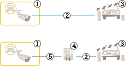
- AXIS License Plate Verifierが搭載されたAxisカメラ
- I/O通信
- ゲート
- Axis I/Oリレーモジュール
- IP通信
既知の車両の場合に、リレーモジュールを使用してゲートを開く
この使用事例では、AXIS License Plate Verifier をリレーモジュールと共に設定して、特定の関心領域 (ROI) を通過して駐車場などに入っていく既知の車両に対してゲートを開く方法を説明します。
- 要件:
カメラがネットワークに物理的に設置および接続されている。
カメラでAXIS License Plate Verifierが起動され実行されている。
バリアとリレーモジュールの間にケーブルが接続されている。
基本的な設定が終了している。を参照してください。
カメラのWebページに移動し、[Settings] (設定) を選択してAXIS License Plate Verifierを開きます。
リレーモジュールのWebページに移動し、リレーポートがカメラのI/Oポートに接続されていることを確認します。
リレーモジュールのIPアドレスをコピーします。
AXIS License Plate Verifierに戻ります。
[Settings (設定)] > [Access control (アクセスコントロール)] に移動します
[Relay (リレー)] を選択します。
以下の情報を入力します。
リレーモジュールのIPアドレスを
192.168.0.0の形式で入力リレーモジュールのユーザー名
リレーモジュールのパスワード
[I/O output (I/O出力)] ドロップダウンリストで、バリアに接続されているI/Oポートを選択します。
[Barrier mode (バリアモード)] で、[Open from lists (リストから開く)] を選択し、[Allowlist (許可リスト)] を確認します。
[Vehicle direction (車両の進行方向)] で、[In (イン)] を選択します。
[Area of interest (対象範囲)] で、車線を含む対象範囲を選択します。
接続が機能することを確認し、[Connect] (接続) をクリックします。
接続をアクティブにするには、[Turn on integration (統合を有効にする)] をクリックします。
[List management (リスト管理)] タブに移動します。
[Allowlist (許可リスト)] フィールドにナンバープレート番号を入力します。
アプリケーションが、許可リストに含まれるナンバープレート番号を既知の車両として識別し、ゲートが正常に開くことを確認してください。
- 注
リレーモジュール上の物理的な入力ポート1~8が、ドロップダウンリストのポート1~8に対応します。ただし、リレーモジュール上のリレーポート1~8は、ドロップダウンリストのポート9~16に対応します。これは、リレーモジュールにポートが8個しかない場合も同じです。
既知の車両の場合に、カメラのI/Oを使用してゲートを開く
この例では、既知の車両が駐車場に入るような場合に、カメラのI/Oポートを使用してゲートを開くようにAXIS License Plate Verifierを設定する方法について説明します。
- 要件:
カメラがネットワークに物理的に設置および接続されている。
カメラでAXIS License Plate Verifierが起動され実行されている。
ゲートとカメラのI/Oポートの間にケーブルが接続されている。
基本的な設定が終了している。を参照してください。
アプリケーションのWebページに移動し、[Home (ホーム)] に移動して、検知されたナンバープレートをリストに追加します。「検知されたナンバープレートをリストに追加する」を参照してください。
リストを直接編集するには、[List management (リスト管理)] に移動します。
[Allowlist (許可リスト)] フィールドに許可されたナンバープレート番号を入力します。
[Settings (設定)] に移動します。
[Access control (アクセスコントロール)] で、[Internal I/O (内部I/O)] を選択します。
[I/O output # (I/O出力番号)] を選択します。
[Barrier mode (バリアモード)] で、[Open from lists (リストから開く)] を選択し、[Allowlist (許可リスト)] を確認します。
[Vehicle direction] (車両の方向) ドロップダウンリストから [in] (入庫) を選択します。
[Area of interest (対象範囲)] で、使用する対象範囲を選択するか、すべての対象範囲を使用するかを選択します。
アプリケーションが、許可リストに含まれるナンバープレート番号を既知の車両として識別し、ゲートが正常に開くことを確認してください。
特定の使用事例に合わせて、任意のリストの名前を変更できます。
許可されていない車両に関する通知を受け取る
この例では、カメラで通知をトリガーするイベントを作成できるように、アプリケーションを設定する方法について説明します。
要件:
基本的な設定が終了している。はじめにを参照してください。
[List management (リスト管理)] に移動します。
[Blocklist (ブロックリスト)] フィールドにナンバープレート番号を入力します。
カメラのWebページに移動します。
[Settings (設定)] > [Events (イベント)] に移動し、アプリケーションを条件とし、通知をアクションとするアクションルールを設定します。
アプリケーションが、追加されたナンバープレート番号を許可されていない車両として識別し、アクションルールが正常に実行されることを確認してください。
車両アクセスコントロールのシナリオ
車両のアクセスコントロールのシナリオでは、アプリケーションをAxisネットワークドアコントローラーに接続して、アクセスルールを設定し、アクセス時間のスケジュールを作成し、従業員だけでなく訪問者やサプライヤーの車両アクセスも処理することができます。
バックアップ用に、ドアコントローラーとカードリーダーを含むアクセスシステムを使用します。ドアコントローラーとカードリーダーを設定する方法については、axis.comにあるユーザードキュメントを参照してください。
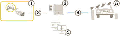
- AXIS License Plate Verifierが搭載されたAxisカメラ
- IP通信
- カードリーダーを備えたAxisネットワークドアコントローラー
- I/O通信
- ゲート
- オプションのサードパーティ製ソフトウェア
ドアコントローラーに接続する
この例では、カメラをネットワークドアコントローラーに接続します。つまり、カメラがセンサーとして機能します。カメラはコントローラーに情報を転送し、コントローラーは情報を分析し、イベントをトリガーします。
これらの手順は、AXIS A1001 Door Controllerのみに適用されます。
AXIS License Plate VerifierとAXIS Entry Managerを切り替える際には、すべてのパラメーターにアクセスできるよう、必ずウェブページを更新してください。
- 要件:
カメラとドアコントローラーが物理的に設置され、ネットワークに接続されている。
カメラでAXIS License Plate Verifierが起動され実行されている。
基本的な設定が終了している。を参照してください。
- AXIS Entry Managerでのハードウェアの設定
AXIS Entry Managerに移動し、[Setup] (設定) で新しいハードウェア設定を開始します。
ハードウェアの設定で、ネットワークドアコントローラーの名前を「ゲート ローラー」に変更します。
[Next (次へ)] をクリックします。
[Configure locks connected to this controller] (このコントローラーに接続されているロックを設定する) で、[Door monitor] (ドアモニター) オプションをクリアします。
[Next (次へ)] をクリックします。
[Configure readers connected to this controller] (このコントローラーに接続されているリーダーを設定する) で、[Exit reader] (外部リーダー) オプションをクリアします。
Finish (終了) をクリックします。
- Configuration in AXIS License Plate Verifierでの設定
AXIS License Plate VerifierのWebページに移動します。
[Settings (設定)] > [Access control (アクセスコントロール)] に移動します。
[Controller (コントローラー)] を選択します。
[Network settings (ネットワーク設定)] で、以下の情報を入力します。
コントローラーのIPアドレスを
192.168.0.0の形式で入力コントローラーのユーザー名
コントローラーのパスワード
[接続] をクリックします。
接続が成功した場合は、[Network Door Controller name] (ネットワークドアコントローラー名) ドロップダウンリストに “Gatecontroller“ が表示されます。[Gatecontroller] を選択します。
[Reader name (リーダー名)] ドロップダウンリストで、ドア“Gatecontroller”に接続されているリーダーを選択します (“Reader entrance”など)。これらの名前は、AXIS Entry Managerで変更できます。
接続をアクティブにするには、[Activate integration (統合をアクティブにする)] をクリックします。
ユーザーのナンバープレート番号の1つを入力するか、デフォルトを使用し、[Test (テスト)] をクリックします。テストが成功したことを確認します。
- AXIS Entry Managerで、ユーザー、グループ、ドア、およびスケジュールを設定する
Go to AXIS Entry Managerに移動します。
[Access Management] (アクセス管理) に移動します。
[Doors > Add identification type] (ドア > 識別タイプを追加) に移動します。
[Credentials needed] (必要な認証情報) ドロップダウンリストで、[License plate only] (ナンバープレートのみ) を選択します。
識別タイプを使用できる時期に制限を設定するには、[Schedule] (スケジュール) をドアにドラッグアンドドロップします。
ユーザーを追加し、ユーザーごとに認証情報の [License plate] (ナンバープレート) を追加します。
再度 [Add credential] (認証情報を追加) クリックし、ナンバープレート情報を入力します。
[Add new group] (新しいグループを追加) をクリックし、情報を入力します。
ユーザーをグループに追加するには、[Users (ユーザー)] をユーザーグループにドラッグアンドドロップします。
ユーザーにアクセス権を付与するには、[Door] (ドア) をユーザーグループにドラッグアンドドロップします。
アクセス時間を制限するには、[Schedule] (スケジュール) をユーザーグループにドラッグアンドドロップします。
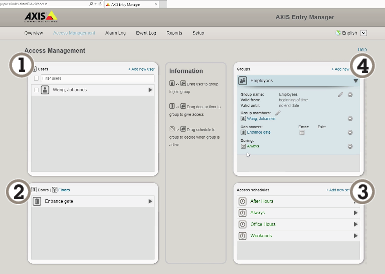
AXIS Entry Managerのユーザーインターフェースの概要。 - ユーザー
- ドア
- スケジュール
- ユーザーグループ
AXIS Secure Entryへの接続
この例では、AXIS Licence Plate Verifierを使用して、AXIS Camera Station内のAxisドアコントローラーとAXIS Secure Entryを接続する方法について説明します。
これらの手順は、A1210、A1201-B、A1214、A1610、A1610-B、A1710-B、およびA1810-Bデバイスのみに適用されます。
- 要件:
カメラとドアコントローラーが物理的に設置され、ネットワークに接続されている。
カメラでAXIS License Plate Verifierが起動され実行されている。
AXIS Camera Stationクライアントバージョン5.49.449以上。
基本的な設定が終了している。を参照してください。
AXIS Camera Stationで、「リーダーの追加」を参照してください。
AXIS License Plate Verifierアプリで、次の操作を行います。
[Settings (設定)] メニューで、[Access control (アクセスコントロール)] に移動し、[Secure Entry] を選択します。
[IP address (IPアドレス)] に移動し、[AXIS Camera Station] > [Configuration (設定)] > [Other Devices (その他のデバイス)] のデバイスリストに表示されるドアコントローラーのIPアドレスを入力します。
- AXIS Camera Stationで、以下の手順に従います。
認証キーを追加するには、[AXIS Camera Station>Configuration>Encrypted communication (AXIS Camera Station>設定>暗号化通信)] に移動します。
[External Peripheral Authentication Key (外部周辺機器認証キー)] に移動し、[Show authentication key (認証キーの表示)] をクリックします。
[Copy key (キーのコピー)] をクリックします。
- AXIS License Plate Verifierアプリで、次の操作を行います。
[Authentication key (認証キー)] に移動し、キーを貼り付けます。
[接続] をクリックします。
車両の進行方向を選択します。
対象範囲を選択します。
ドロップダウンメニューで、[Door controller name (ドアコントローラー名)] を選択します。
ドロップダウンメニューで、[Reader name (リーダー名)] を選択します。
[Activate integration (統合をアクティブにする)] をクリックします。
ユーザーのナンバープレート番号の1つを入力するか、デフォルトを使用し、[Test (テスト)] をクリックします。テストが成功したことを確認します。
速度測定によるフリーフローシナリオ
速度測定によるフリーフローシナリオでは、カメラはエッジツーエッジテクノロジーによってAxisレーダーとペアリングされます。カメラは2車線をカバーし、通過車両のナンバープレートを読み取り、ペアリングされたレーダーも同じ2車線をカバーし、車両の速度を測定します。さらに、AXIS Speed Monitorアプリケーションは、カメラのライブビューのオーバーレイを介して各車線の最高速度を表示できます。
エッジツーエッジの詳細については、エッジツーエッジ技術を参照してください。
要件:
AXIS License Plate VerifierカメラキットとAXIS D2210-VE Radarがインストールされ、ネットワークに接続されていること。
シナリオを設定する
4つのステップでシナリオを設定します。まずカメラを設定し、次にレーダーをペアリングおよび設定して、最後にAXIS Speed Monitorを使ってオーバーレイを追加します。
開始する前に、以下をご確認ください。
カメラとレーダーが同じ対象範囲に向けられていることを確認します。
カメラとレーダーの時刻が同期していることを確認します。ステータスを確認するには、各装置の [Installation > Time sync status (インストール > 時刻同期ステータス)] に移動します。
- カメラを設定する:
の手順に従ってカメラを設定します。
設定アシスタントに従うときは、必ずフリーフローを選択してください。詳細については、フリーフローを参照してください。
- カメラをレーダーとペアリングする:
カメラのwebインターフェースで、[System > Edge-to-edge > Radar pairing (システム > エッジツーエッジ > レーダーペアリング)] に移動します。
レーダーのホスト名、ユーザー名、パスワードを入力します。
[Connect (接続)] をクリックして装置をペアリングします。
接続が確立されると、カメラのwebインターフェースでレーダーの設定を利用できます。
- 注
ペアリングされたレーダーのデフォルトの解像度は1280x720です。レーダーをVMSに追加する場合、カメラのwebインターフェースでレーダーのデフォルト解像度を維持します。
- レーダーの設定:
カメラのwebインターフェースで、[Radar > Scenarios (レーダー > シナリオ)] に移動します。
片方の車線をカバーするレーダーシナリオと、もう片方の車線をカバーするレーダーシナリオを追加します。
どちらのシナリオでも、[Movement in area (エリアへの侵入)] を選択し、[Vehicles (車両)] をトリガーして [Speed limit (制限速度)] を設定します。
詳細については、AXIS D2210-VE Radarユーザーマニュアルのシナリオを追加するを参照してください。
AXIS License Plate Verifierからのナンバープレート情報を含むオーバーレイを追加する場合は、AXIS Speed Monitorでオーバーレイを追加する前に、これらのオーバーレイを追加してください。
- 以下の手順に従って、AXIS Speed Monitorを使用して、速度オーバーレイを追加します。
AXIS Speed Monitorをカメラにダウンロードしてインストールします。
各車線に1つのオーバーレイを追加すると、カメラのライブビューで最大速度が表示されます。
インストールと設定の手順については、AXIS Speed Monitorユーザーマニュアルを参照してください。
特定のイベントの検索
複数の条件を使用してイベントを検索するには、検索機能を使用します。
アプリケーションのWebページに移動し、[Search (検索)] ページを選択します。
[From (開始)] および [To (終了)] カレンダーメニューで日付を選択し ます。
[AOI] のドロップダウンメニューをクリックし、検索対象範囲を選択します。
[Direction (方向)] を選択して、入場または退出でフィルターします。
ナンバープレートを検索する場合は、[Plate (ナンバープレート)] フィールドにナンバープレートを入力します。
特定の国に属するナンバープレートを検索するには、[Country (国)] のドロップダウンリストから国を選択します。
車両のビューに基づいて画像を絞り込むには、[Vehicle view] のドロップダウンリストから [Front (前)] または [Rear (後)] を選択します。
車両のメーカー、モデル、タイプ、またはカラーに基づいて検索結果を絞り込むには、[Vehicle details (車両の詳細)] のドロップダウンメニューから該当項目を選択します。
[Apply filters (フィルターを適用する)] をクリックし、検索結果を表示します。
統合
プロファイルを使用して、複数のサーバーにイベントをプッシュする
プロファイルを使用すると、異なるプロトコルを使用する異なるサーバーに、同時にイベントをプッシュすることができます。プロファイルを使用する方法:
[Integration (統合)] および [Push events (イベントのプッシュ)] ページに移動します。
[Profile 1 (プロファイル1)] を選択します。
ルールを設定します。サードパーティ製ソフトウェアへのイベント情報のプッシュを参照してください。
ルールをテストします。
新しいプロファイルのタブを選択し、新しいルールを設定します。
サードパーティ製ソフトウェアへのイベント情報のプッシュ
アプリケーションは、JSON形式でイベント情報を送信します。詳細については、MyAxisアカウントを使用してログインし、AXIS VAPIXライブラリに移動して、AXIS License Plate Verifierを選択してください。
この機能を使用すると、TCPまたはHTTP POSTでイベントデータをプッシュして、サードパーティ製ソフトウェアを統合することができます。
- 開始する前に、以下をご確認ください。
カメラはネットワークに物理的に設置および接続されている必要があります。
カメラでAXIS License Plate Verifierが起動されて実行されている必要があります。
[Integration (統合)] > [Push events (イベントのプッシュ)] に移動します。
空のプロファイルを選択します。
[Protocol (プロトコル)] ドロップダウンリストで、[HTTP POST] を選択します。
[Server URL (サーバーのURL)] フィールドに、次の形式でサーバーのアドレスとポートを入力します:
127.0.0.1:8080ユーザー名とパスワードを入力します。
プロキシーを使用している場合は、プロキシーをオンにし、ホスト名、ユーザー名、パスワードを入力します。
[Device ID (デバイスID)] フィールドに装置の名前を入力するか、そのままにします。
[Push conditions (プッシュ条件)] でプッシュイベントをトリガーする方向を選択します。
[LPR Event types (LPRイベントタイプ)] で、以下のオプションから1つ以上選択します。
[New (新規)] は、ナンバープレートが初めて検知されたことを意味します。
[Update (更新)] は、以前に検知されたナンバープレートの文字を修正する場合と、プレートの移動に伴って方向が検知され、画像上で追跡される場合のどちらかです。
[Lost (消失)] は、ナンバープレートが画像から出る前の最後の追跡イベントです。これには、ナンバープレートの方向も含まれます。
[Conditional (条件付き)] は、条件が満たされた場合に、1つのオブジェクトに対して1つのイベントをプッシュします。
HTTP POSTを使用する際に帯域幅を削減するには、[Do not to send images (画像を送信しない)] を選択します。
[Event buffer (イベントバッファ)] を有効にし、サーバーがダウンした場合にイベントをバッファリングしてサーバーが利用可能になったら送信するようにします。
[Retention settings (保持設定)] で選択している場合、画像に加えてナンバープレートの切り取り画像を含めるには、[Send two images (2つの画像を送信)] を選択します。
Base64形式ではなくmulitpart形式でイベントを送信するには、[Multipart] を選択します。
[Test (テスト)] をクリックし、仮想ナンバープレートを使用して統合テストを行います。
この機能をオンにするには、[Activate (オンにする)] を選択します。
- 注
HTTP POSTを使用してイベントをプッシュするには、ユーザー名とパスワードの代わりに認証ヘッダーを使用し、[Auth-Header (認証ヘッダー)] に移動し、認証APIへのパスを追加します。
サーバーへのナンバープレートの画像の送信
この機能を使用すると、FTPを介してナンバープレートの画像をサーバーにプッシュできます。
- 開始する前に、以下をご確認ください。
カメラはネットワークに物理的に設置および接続されている必要があります。
カメラでAXIS License Plate Verifierが起動されて実行されている必要があります。
[Integration (統合)] > [Push events (イベントのプッシュ)] に移動します。
[Protocol (プロトコル)] ドロップダウンリストで、[FTP] を選択します。
[Server URL (サーバーのURL)] フィールドに、以下の形式でサーバーのアドレスを入力します:
ftp://10.21.65.77/LPRFTPサーバーのユーザー名とパスワードを入力します。
ファイル名のパスと名前の修飾子を選択します。
[Device ID (デバイスID)] フィールドにデバイスの名前を入力します。この名前のフォルダーが画像用に作成されます。画像は次の形式で作成されます: timestamp_area of interest_direction_carID_license plate text_country.jpg
[Push conditions (プッシュ条件)] でプッシュイベントをトリガーする方向を選択します。
[Event types (イベントタイプ)] で、以下のオプションから1つ以上選択します。
[New (新規)] は、ナンバープレートが初めて検知されたことを意味します。
[Update (更新)] は、以前に検知されたナンバープレートの文字を修正する場合と、プレートの移動に伴って方向が検知され、画像上で追跡される場合のどちらかです。
[Lost (消失)] は、ナンバープレートが画像から出る前の最後の追跡イベントです。これには、ナンバープレートの方向も含まれます。
[Conditional (条件付き)] は、条件が満たされた場合に、1つのオブジェクトに対して1つのイベントをプッシュします。
- 注
[Lost (消失)] または [Update (更新)] が選択されている場合、方向はファイル名にのみ含まれます。
[Test (テスト)] をクリックし、仮想ナンバープレートを使用して統合テストを行います。
この機能をオンにするには、[Activate (オンにする)] をクリックします。
選択したキャプチャーモードのタイプによって画像が異なることに注意してください (画像キャプチャーの設定を調整するを参照してください)。
プッシュイベントが失敗した場合、アプリは失敗した最初の100件までをサーバーに再送信します。
WindowsサーバーへのプッシュイベントでFTPを使用する場合、画像の名前に日付と時刻を示す「%c」を使用しないでください。これは、Windowsが日付と時刻に対して関数「%c」で設定された名前を許容していないためです。 Linuxサーバーを使用する場合には、この問題は発生しません。
2Nとの直接統合
この例では、2N IP装置との直接統合について説明します。
- 2Nデバイスで、次のようにアカウントを設定します。
2N IP Versoに移動します。
[Services (サービス)] > [HTTP API] > [Account 1 (アカウント1)] に移動します。
[Enable account (アカウントを有効にする)] を選択します。
[Camera access (カメラアクセス)] を選択します。
[License plate recognition (ナンバープレート認識)] を選択します。
IPアドレスをコピーします。
- AXIS License Plate Verifierアプリで、次の操作を行います。
[Integration (統合)] > [Direct integration (直接統合)] に移動します
[2N IP Device] を選択します。
IPアドレスまたはURLを2Nデバイスに追加します。
ユーザー名とパスワードを入力します。
[Connection type (接続タイプ)] を選択します。
[Barrier is used for (ゲートの使用目的)] で該当する目的を選択します。
[Enable integration (統合を有効にする)] をクリックします。
車両の進行方向を選択します。
この機能をオンにするには、[Activate (オンにする)] を選択します。
統合が機能していることを確認するには、次の操作を行います。
2N IP Versoに移動します。
[Status (ステータス)] > [Events (イベント)] に移動します。
Genetec Security Centerとの統合
この例では、Genetec Security Centerとの直接統合の設定について説明します。
Genetec Security Centerで、次の操作を行います。
[Overview (概要)] に移動します。
Database (データベース)、Directory (ディレクトリ)、License (ライセンス) がオンラインであることを確認します。オンラインでない場合は、WindowsですべてのGenetecサービスとSQLEXPRESSサービスを実行します。
[Genetec Config Tool] > [Plugins (プラグイン)] に移動します。
[Add an entity (エンティティの追加)] をクリックします。
[Plugin (プラグイン)] に移動し、[LPR plugin (LPRプラグイン)] を選択します。
[Next (次へ)] をクリックします。
[Next (次へ)] をクリックします。
[Next (次へ)] をクリックします。
追加したLPRプラグインを選択し、[Data sources (データソース)] に移動します。
- [ALPR reads API] で、次の操作を行います。
[Enabled (有効)] チェックボックスをオンにします。
[Name (名前)] に、次のように入力します。Plugin REST API。
[API path prefix (APIパスのプレフィックス)] に、次のように入力します: lpr。
[REST port (RESTポート)] で、[443] を選択します。
[WebSDK host (WebSDKホスト)] に、次のように入力します: localhost。
[WebSDK port (WebSDKポート)] で、[443] を選択します。
[Allow self-signed certificates (自己署名証明書を許可する)] チェックボックスをオンにします。
- [Security Center events data source (Security Centerイベントデータソース)] で、次の操作を行います。
[Enabled (有効)] チェックボックスをオンにします。
[Name (名前)] に、「Security Center Lpr Events」と入力します。
[Processing frequency (処理頻度)] で、ドロップダウンメニューから [5 sec (5秒)] を選択します。
[Data sinks (データシンク)] タブに移動します。
[+] をクリックします。
[Type (タイプ)] で [Database (データベース)] を選択します。
データベースを選択し、次のように設定します。
[Enabled (有効)] チェックボックスをオンにします。
[Source (ソース)] で、[Plugin REST API] と [Native ALPR Events (ネイティブALPRイベント)] チェックボックスをオンにします。
[Name (名前)] に、「Reads DB」と入力します。
[Include (含める)] で、[Reads]、[Hits]、[Images] チェックボックスをオンにします。
[Resources (リソース)] タブに移動します。
[Delete the database (データベースの削除)] をクリックした後、[Create a database (データベースの作成)] をクリックします。
- Create an API user (APIユーザーの作成):
[Config Tool] > [User Management (ユーザー管理)] に移動します。
[Add an entity (エンティティの追加)] をクリックします。
[User (ユーザー)] を選択します。
ユーザー名とパスワードを入力します。他のフィールドは変更しないでください。
追加したユーザーを選択し、[Privileges (権限)] タブに移動します。
[Application privileges (アプリケーション権限)] で、すべてを許可するチェックボックスをオンにします。
Third-party ALPR reads API (サードパーティ製ALPR reads API) を許可するチェックボックスをオンにします。
[適用] をクリックします。
AXIS License Plate Verifierアプリで、次の操作を行います。
[Integration (統合)] > [Direct integration (直接統合)] に移動します。
[Genetec Security Center] を選択します。
[URL/IP] に、このテンプレートに従ってアドレスを入力します:
https://server-address/api/V1/lpr/lpringestion/reads。Genetecのユーザー名とパスワードを入力します。
[Connection type (接続タイプ)] を選択します。
この機能をオンにするには、[Activate (オンにする)] を選択します。
[Test (テスト)] をクリックし、仮想ナンバープレートを使用して統合テストを行います。
HTTPSを選択している場合は、[Settings (設定)] タブに移動します。
[Security (セキュリティ)] > [HTTPS] で、次の操作を行います。
Genetec Security Centerの設定に応じて、[Self-signed (自己署名)] または [CA-signed (CA署名)] を選択します。
Genetec Security Centerで、次の操作を行います。
[Genetec Security desk] に移動します
[Investigation (調査)] で、[Reads (読み取り)] をクリックします。
[Reads (読み取り)] タブに移動します。
ニーズに合わせて結果をフィルター処理します。
[レポートを生成する] をクリックします。
Genetecのサードパーティ製ALPRプラグインの統合に関するドキュメントも読むことができます。この操作は、ここで行います (登録が必要)。
webインターフェース
AXIS OS搭載デバイスのWebインターフェースで利用可能なすべての機能および設定については、AXIS OS Webインターフェースヘルプを参照ください。
詳細情報
表示エリア
ビューエリアは、全体画像から一部をクリッピングした画像です。全体画像の代わりにビューエリアをストリーミングおよび保存することで、必要な帯域幅とストレージ容量を最小限に抑えることができます。ビューエリアに対してPTZを有効にすると、そのビューエリア内でパン/チルト/ズームを行うことができます。ビューエリアを使用すると、空など全体画像の一部を削除することができます。
ビューエリアを設定するときは、ビデオストリームの解像度をビューエリアのサイズ以下のサイズにすることをお勧めします。ビデオストリームの解像度をビューエリアのサイズより大きいサイズに設定すると、センサーがキャプチャーした後にビデオがデジタルで拡大されるため、画像情報の追加なしでも必要な帯域幅が増えます。
キャプチャーモード
キャプチャーモードは、カメラが画像をキャプチャーする方法を定義するプリセット設定です。
キャプチャーモード設定により、本装置で利用可能な最大解像度と最大フレームレートを調整できます。
最大解像度よりも低い解像度のキャプチャーモードを使用した場合、視野が狭くなることがあります。
キャプチャーモードはシャッター速度にも影響し、結果として光感度に影響します。これは、最大フレームレートが高いキャプチャーモードでは光感度が下がり、逆に最大フレームレートが低いキャプチャーモードでは、光感度が上がるためです。
キャプチャーモードによっては、WDRを使用できません。
低解像度のキャプチャーモードは、オリジナルの解像度からサンプリングする場合もあれば、オリジナルから切り出す場合もあり、その場合は視野も影響を受けることになります。
どのキャプチャーモードを選択するかは、特定の監視設定でのフレームレートと解像度の要件によって異なります。利用できるキャプチャーモードの仕様については、axis.comで製品のデータシートを参照してください。
ユースケース
一般的な監視
デフォルト設定と連続赤外線を使用します。
デュアルキャプチャーモード
WDRなしでキャプチャーモードを30フレーム/秒に設定すると、カメラは30フレーム/秒のチャンネルを1つ提供します。ビューエリアを追加すると、30フレーム/秒のチャンネルをもう1つ提供します。
ストロボ同期: ストロボ同期を使用する場合、1フレームおきに1回のみストロボ発光します。すなわち、一度に照明が当たるのは1つのチャンネルのみで、1フレームおきにもう一方のチャンネルに移動します。Sync Out (同期出力) 信号は1フレームおきにトリガーするため、1フレームにつき1つのチャンネルのみ外部光を受けます。
連続点灯と赤外線照明のストロボ発光の組み合わせ: 外部光は1フレームおきにストロボ発光させ、内蔵LEDを連続点灯させることができます。これにより、両方のチャンネルが光を受けますが、片方のチャンネルの光がはるかに強くなります。
この設定は、1つのチャンネルでナンバープレートをキャプチャーし、もう1つのチャンネルでフロントガラスの向こう側をキャプチャーしたい場合に最適です。フロントガラスにはかなり強い光が必要なため、同じチャンネルに適用するとナンバープレートが白飛びすることがあります。
デュアルキャプチャーモードを開始するには:
[Capture mode (キャプチャーモード)] に2048x1536 @ 30 fps (WDRなし) を選択します。
[View areas (ビューエリア)] に移動し、 アイコンをクリックして新規のビューエリアを作成します。
2つ目のチャンネルが利用可能になり (ストロボは表示されません)、<IP-address>/mjpg/2/video.mjpgからアクセスできます。
デイモードでは、ビデオに赤外線は表示されず、どちらのチャンネルも同じように見えます。
外部ライトの設定
外部赤外線イルミネーターまたは可視光イルミネーターは、特に交通監視やその他の高速で移動する物体など、非常に短いシャッター時間を必要とするアプリケーションにおいて、画質を大幅に向上させることができます。AXIS P1486-LE Global Shutter Cameraには、電気的な同期信号を出力するSync Out I/O (同期出力I/O) ポートがあります。この信号は、センサーが露光しているときはハイレベルになり、露光していないときはローレベルになります。Sync Out (同期出力) ポートを使用して外部イルミネーターをトリガーし、カメラと同期してストロボ発光させます。
推奨される物理設定
イルミネーターをカメラ本体のベースにあるSync Out (同期出力) ポートに接続します。
[System (システム)] > [Accessories (アクセサリー)] に移動し、[Sync Out I/O port (同期出力I/Oポート] を有効にします。
イルミネーターを電源に接続します。
取扱説明書に従ってイルミネーターを設定します。最大デューティサイクルと最大パルス長に注意して、カメラのフレームレートと最大シャッタースピードに合わせます。
イルミネーターをカメラの画像の撮影範囲と同じ方向に向けます。
- ナイトモードの同期に関する詳細については、以下を参照してください。外部照明をデイ/ナイトモードに同期させる
- 注
一部のイルミネーターは、カメラがWDRモードのとき、想定通りに動作しないことがあります。WDRモードのとき、カメラは1フレームにつき、間に非常に短い遅延のある2つの同期パルスを送信します。外部イルミネーターの使用時に画像の乱れが現れる場合は、WDRを無効にしてください。
素早い動きを伴う一般的な監視
動きをはっきりととらえることを優先する場合は、最大シャッター時間を下げて露出時間を短くし、移動する物体のキャプチャー精度を高めます。最大の効果を得るには、同期ストロボ設定を使用してください。
ナンバープレートキャプチャー
内蔵LEDと[Scene profile: License plate (シーンプロファイル: ナンバープレート)]を使用します。これにより、シャッター時間や最大ゲインが制限され、その他の設定が最適化されます。
フロントガラスの向こう側
フロントガラスの向こう側をキャプチャーするには、外部ストロボイルミネーターによる高い出力が必要です。イルミネーターの位置をカメラの視野 (FOV) に合わせます。外部イルミネーターは、カメラと同期するように設定する必要があります。
ストロボ赤外線照明を別のローリングシャッター方式のカメラと一緒に使用する場合、同期キャプチャーを使用する必要があることがあります。
ナンバープレート + フロントガラスの向こう側
以下の2つの方法が可能です。
[License plate scene profile (ナンバープレートシーンプロファイル)] を選択し、外部イルミネーターをカメラから3~4 m (10~13 ft) 離れた位置に設置します (横、上、または下。カメラの前または後ろには設置しないでください)。画像設定を最適化するには、[License plate scene profile (ナンバープレートシーンプロファイル)]を使用してください。
[Dual capture mode (デュアルキャプチャーモード)] を使用して、2つのビデオチャンネルを生成します。1つは車両とその車内を映し出し、もう1つはナンバープレートを明瞭に映し出します。画像設定を最適化するには、[License plate scene profile (ナンバープレートシーンプロファイル)]を使用してください。
フロントガラスの向こう側およびナンバープレート認識 (LPR) にデュアルキャプチャーモードを使用するには:
上記の[Dual capture mode (デュアルキャプチャーモード)]を起動します。
高性能外部ストロボランプをSync Out I/O (同期出力I/O) ポートに接続し、そのポートを有効にします。カメラの画像範囲の方向にランプを向けます。強いストロボ赤外線照明は、1つ目 (デフォルト) のチャンネルでのみ確認できます。
[Synchronized strobe (ストロボ同期)]を[Off (オフ)]に設定します。これにより、内蔵赤外線LEDが連続モードに切り替わり、2つ目のチャンネルでより弱い赤外線照明が確認できるようになります。
プライバシーマスク
プライバシーマスクは、監視領域の一部を隠すユーザー定義のエリアです。ビデオストリームでは、プライバシーマスクは塗りつぶされたブロックまたはモザイク模様として表示されます。
プライバシーマスクは、すべてのスナップショット、録画されたビデオ、ライブストリームに表示されます。
VAPIX®アプリケーションプログラミングインターフェース (API) を使用して、プライバシーマスクを非表示にすることができます。
複数のプライバシーマスクを使用すると、製品のパフォーマンスに影響する場合があります。
複数のプライバシーマスクを作成できます。各マスクには3~10個のアンカーポイントを設定できます。
プライバシーマスクを作成する前に、ズームとフォーカスを設定します。
オーバーレイ
オーバーレイは、ビデオストリームに重ねて表示されます。オーバーレイは、タイムスタンプなどの録画時の補足情報や、製品のインストール時および設定時の補足情報を表示するために使用します。テキストまたは画像を追加できます。
ビデオストリーミングインジケーターは、別のタイプのオーバーレイです。これは、ライブビューのビデオストリームが動作中であることを示します。
PoE Class 3で接続する場合、SIP通話を除くすべてのビデオストリームにオーバーレイが含まれます。
パン、チルト、ズーム (PTZ)
ガードツアー
ガードツアーを使用して、さまざまなプリセットポジションからのビデオストリームを、設定した時間中、あらかじめ決められた順序またはランダムな順序で表示することができます。ガードツアーを開始すると、映像を視聴しているクライアント (Webブラウザ) が存在しなくなったとしても、停止されるまで動作が継続されます。
ストリーミングとストレージ
ビデオ圧縮形式
使用する圧縮方式は、表示要件とネットワークのプロパティに基づいて決定します。以下から選択を行うことができます。
Motion JPEG
Opus音声コーデックを確実にサポートするために、Motion JPEGストリームが常にRTP経由で送信されます。
Motion JPEGまたはMJPEGは、個々のJPEG画像の連続で構成されたデジタルビデオシーケンスです。これらの画像は、十分なレートで表示、更新されることで、連続的に更新される動きを表示するストリームが作成されます。人間の目に動画として認識されるためには、1秒間に16以上の画像を表示するフレームレートが必要になります。フルモーションビデオは、1秒間に30フレーム (NTSC) または25フレーム (PAL) で動画と認識されます。
Motion JPEGストリームは、かなりの帯域幅を消費しますが、画質に優れ、ストリームに含まれるすべての画像にアクセスできます。
H.264またはMPEG-4 Part 10/AVC
H.264はライセンスされた技術です。このAxis製品には、H.264閲覧用のクライアントライセンスが1つ添付されています。ライセンスされていないクライアントのコピーをインストールすることは禁止されています。ライセンスを追加購入するには、Axisの販売代理店までお問い合わせください。
H.264を使用すると、画質を損なうことなく、デジタル映像ファイルのサイズを削減でき、Motion JPEG形式の場合と比較すると80%以上、従来のMPEG形式と比較すると50%以上を削減できます。そのため、ビデオファイルに必要なネットワーク帯域幅やストレージ容量が少なくなります。また、別の見方をすれば、より優れた映像品質が同じビットレートで得られることになります。
H.265またはMPEG-H Part 2/HEVC
H.265を使用すると、画質を損なうことなくデジタルビデオファイルのサイズを削減でき、H.264に比べて25%以上縮小することができます。
- H.265はライセンスされた技術です。このAxis製品には、H.265閲覧用のクライアントライセンスが1つ添付されています。ライセンスされていないクライアントのコピーをインストールすることは禁止されています。ライセンスを追加購入するには、Axisの販売代理店までお問い合わせください。
- ほとんどのWebブラウザはH.265のデコードに対応していないため、カメラはWebインターフェースでH.265をサポートしていません。その代わり、H.265のデコーディングに対応した映像管理システムやアプリケーションを使用できます。
画像、ストリーム、およびストリームプロファイルの各設定の相互関連性について
[Image (画像)] タブには、製品からのすべてのビデオストリームに影響を与えるカメラ設定が含まれています。このタブで変更した内容は、すべてのビデオストリームと録画にすぐに反映されます。
[Stream (ストリーム)] タブには、ビデオストリームの設定が含まれています。解像度やフレームレートなどを指定せずに、製品からのビデオストリームを要求している場合は、これらの設定が使用されます。[Stream (ストリーム)] タブで設定を変更すると、実行中のストリームには影響しませんが、新しいストリームを開始したときに有効になります。
[Stream profiles (ストリームプロファイル)] の設定は、[Stream (ストリーム)] タブの設定よりも優先されます。特定のストリームプロファイルを持つストリームを要求すると、ストリームにそのプロファイルの設定が含まれます。ストリームプロファイルを指定せずにストリームを要求した場合、または製品に存在しないストリームプロファイルを要求した場合、ストリームに [Stream (ストリーム) タブの設定が含まれます。
ビットレート制御
ビットレート制御で、ビデオストリームの帯域幅の使用量を管理することができます。
可変ビットレート (VBR)
可変ビットレートでは、シーン内の動きのレベルに基づいて帯域幅の使用量が変化します。シーン内の動きが多いほど、多くの帯域幅が必要です。ビットレートが変動する場合は、一定の画質が保証されますが、ストレージのマージンを確認する必要があります。
最大ビットレート (MBR)
最大ビットレートでは、目標ビットレートを設定してシステムのビットレートを制限することができます。瞬間的なビットレートが指定した目標ビットレート以下に保たれていると、画質またはフレームレートが低下することがあります。画質とフレームレートのどちらを優先するかを選択することができます。目標ビットレートは、予期されるビットレートよりも高い値に設定することをお勧めします。これにより、シーン内で活動レベルが高い場合にマージンを確保します。
- 目標ビットレート
平均ビットレート (ABR)
平均ビットレートでは、より長い時間スケールにわたってビットレートが自動的に調整されます。これにより、指定した目標を達成し、使用可能なストレージに基づいて最高画質のビデオを得ることができます。動きの多いシーンでは、静的なシーンと比べてビットレートが高くなります。平均ビットレートオプションを使用すると、多くのアクティビティがあるシーンで画質が向上する可能性が高くなります。指定した目標ビットレートに合わせて画質が調整されると、指定した期間 (保存期間)、ビデオストリームを保存するために必要な総ストレージ容量を定義できます。次のいずれかの方法で、平均ビットレートの設定を指定します。
必要なストレージの概算を計算するには、目標ビットレートと保存期間を設定します。
使用可能なストレージと必要な保存期間に基づいて平均ビットレートを計算するには、目標ビットレートカリキュレーターを使用します。
- 目標ビットレート
- 実際の平均ビットレート
- 平均ビットレートオプションの中で、最大ビットレートをオンにし、目標ビットレートを指定することもできます。
- 目標ビットレート
- 実際の平均ビットレート
エッジツーエッジ技術
エッジツーエッジは、IP装置が相互に直接通信できるようにする技術です。たとえば、AxisのカメラとAxisの音声/レーダー製品との間のスマートペアリング機能を提供します。
ペアリングされたデバイスが同じAXIS OSバージョンで動作していることを確認してください。
詳しくは、whitepapers.axis.com/edge-to-edge-technology でホワイトペーパー“Edge-to-edge technology”(エッジツーエッジ技術) を参照してください。
スピーカーのペアリング
エッジツーエッジのスピーカーペアリングにより、対応するAxisネットワークスピーカーをカメラの一部であるかのように使用できます。ペアリングすると、スピーカーの機能はカメラのwebインターフェースに統合され、ネットワークスピーカーは音声出力装置として機能し、音声クリップを再生したり、カメラを介して音声を送信したりすることができます。
カメラはVMSで音声出力を内蔵したカメラであると識別され、再生された音声をスピーカーにリダイレクトします。
マイクのペアリング
エッジツーエッジのマイクペアリングにより、対応するマイクをカメラの一部であるかのように使用できます。ペアリングされると、マイクロフォンは周辺エリアからの音声を取り込み、音声入力装置として使用し、メディアストリームや録画で使用できます。
分析機能とアプリ
分析機能とアプリを使用することで、Axisデバイスをより活用できます。AXIS Camera Application Platform (ACAP) は、サードパーティによるAxisデバイス向けの分析アプリケーションやその他のアプリの開発を可能にするオープンプラットフォームです。アプリとしては、デバイスにプリインストール済み、無料でダウンロード可能、またはライセンス料が必要なものがあります。
Axisの分析機能とアプリのユーザーマニュアルは、help.axis.comから参照できます。
- 同時に複数のアプリケーションを実行できますが、互いに互換性がないアプリケーションもあります。アプリケーションの特定の組み合わせによっては、並行して実行すると過度の処理能力やメモリーリソースが必要になる場合があります。展開する前に、各アプリを組み合わせて実行できることを確認してください。
AXIS Image Health Analytics
AIベースのアプリケーション「AXIS Image Health Analytics」により、画像の劣化や改ざんの試みを検知することができます。このアプリケーションにより、シーンの動作を分析して学習すること、画像のぼやけや露出不足を検知すること、また遮られた視界や方向転換した視界を検知することができます。検知された対象に対してイベントを送信するようにアプリケーションを設定し、カメラのイベントシステムまたはサードパーティ製ソフトウェアを通じてアクションをトリガーすることができます。
アプリケーションの動作の詳細については、AXIS Image Health Analyticsユーザーマニュアルを参照してください。
メタデータの可視化
分析メタデータは、シーン内の動く物体に使用できます。サポートされている物体クラスが、物体のタイプと分類の信頼度に関する情報と共に、物体を囲む境界ボックスにより、ビデオストリームに可視化されます。分析メタデータの設定および使用方法の詳細については、AXIS Scene Metadata統合ガイドを参照してください。
仕様
製品概要
- ステータスLEDインジケーター
- コントロールボタン
- 音声コネクター
- I/Oコネクター
- 安全ワイヤー
- microSDカードスロット
- ネットワーク コネクター
- DC電源入力
- Sync out (同期出力)
- アース端子ネジ
LEDインジケーター
| ステータスLED | 説明 |
| 消灯 | 接続時および正常動作時です。 |
| 緑 | 起動後正常に動作する場合、10秒間、緑色に点灯します。 |
| 黄色 | 起動時に点灯.装置のソフトウェアのアップグレード中、または工場出荷時の設定にリセット中に点滅します。 |
| オレンジ/赤 | ネットワーク接続が利用できないか、失われた場合は、オレンジ色/赤色で点滅します。 |
| 赤 | 装置のソフトウェアのアップグレードに失敗しました。 |
SDカードスロット
- カードが損傷する恐れがあります。SDカードの挿入または取り出しの際は、鋭利な道具や金属物を使用したり過度な力をかけたりしないでください。カードの挿入または取り出しは指で行ってください。
- データ損失や録画データ破損の危険があります。SDカードを取り外す前に、装置のwebインターフェースからマウント解除してください。本製品の稼働中はSDカードを取り外さないでください。
本装置は、microSD/microSDHC/microSDXCカードに対応しています。
推奨するSDカードについては、axis.comを参照してください。


 microSD、microSDHC、およびmicroSDXCロゴは、SD-3C LLCの商標です。microSD、microSDHC、microSDXCは、米国および/または他の国々におけるSD-3C, LLCの商標または登録商標です。
ボタン
コントロールボタン
- コントロールボタンは、以下の用途で使用します。
製品を工場出荷時の設定にリセットする。工場出荷時の設定にリセットします。を参照してください。
インターネット経由でワンクリッククラウド接続 (O3C) サービスに接続します。接続するには、ボタンを押してから放し、ステータスLEDが緑色に3回点滅するまで待ちます。
コネクター
ネットワーク コネクター
Power over Ethernet (PoE) 対応RJ45イーサネットコネクター
音声コネクター
音声入力 - モノラルマイクロフォンまたはラインインモノラル信号用 (左チャンネルはステレオ信号で使用) 3.5 mm入力。
音声入力 - 2つのモノラルマイクロフォンまたは2つのライン入力モノラル信号用 (付属のステレオ-モノラルアダプターを使用) 3.5 mm入力。
音声入力
| 1 チップ | 2 リング | 3 スリーブ |
アンバランス型マイクロフォン (エレクトレット電源あり、なし) またはライン入力 | 選択されている場合、エレクトレット電源 | アース |
I/Oコネクター
I/Oコネクターに外部装置を接続し、動体検知、イベントトリガー、アラーム通知などと組み合わせて使用することができます。I/Oコネクターは、0 VDC基準点と電力 (12V DC出力) に加えて、以下のインターフェースを提供します。
- デジタル入力
- 開回路と閉回路の切り替えが可能な装置 (PIRセンサー、ドア/窓の接触、ガラス破損検知器など) を接続するための入力です。
- デジタル出力
- リレーやLEDなどの外部デバイス接続用。接続された装置は、VAPIX®アプリケーションプログラミングインターフェースを通じたイベントまたは本装置のwebインターフェースから有効にすることができます。
4ピンターミナルブロック
| 機能 | ピン | メモ | 仕様 |
| DCアース | 1 | 0 VDC | |
| DC出力 | 2 | 補助装置の電源供給に使用できます。 | 12VDC 最大負荷 = 25mA |
| デジタル入力 | 3 | 動作させるにはピン1に接続し、動作させない場合はフロート状態 (未接続) のままにします。 | 0~最大30 VDC |
| デジタル出力 | 4 | アクティブ時はピン1 (DCアース) に内部で接続し、非アクティブ時はフロート状態 (未接続) になります。リレーなどの誘導負荷とともに使用する場合は、過渡電圧から保護するために、負荷と並列にダイオードを接続します。 | 0~30 VDC (最大)、オープンドレイン、100 mA |
例
- DCアース
- DC出力12 V、最大25 mA
- デジタル入力
- デジタル出力
接続例
Sync Out (同期出力)
「Sync Out」(同期出力) と表示された追加の出力もあり、外部ストロボをトリガーするために使用できます。これにより、カメラが画像をキャプチャーするときに照明を同期させることができます。
| 機能 | ピン | メモ | 仕様 |
| Sync Out (同期出力) | 1 | 画像キャプチャー中のパルス出力は、外部ストロボ光源のトリガーとして使用できます。 Pulse (パルス):12 V DCでのハイサイドスイッチ出力。 Dead time (デッドタイム):フロート状態。Sync Out (同期出力) のパルス出力を正しく測定するには、外部負荷を接続する必要があります。 | 12VDC 最大負荷 = 25mA |
| アース | 2 | 0 VDC |
Sync Out (同期出力) ポートは、デフォルトで無効になっています。外部ストロボライトを使用するには、Sync Out (同期出力) ポートを有効にする必要があります。有効にすると、Sync Out (同期出力) 信号が日中と夜間の両方でアクティブになります。日中のSync Out (同期出力) を無効にするには、システムイベントをそれに応じて設定する必要があります。
電源コネクター
DC電源入力用2ピンターミナルブロック。定格出力が100 W以下または5 A以下の安全特別低電圧 (SELV) に準拠した有限電源 (LPS) を使用してください。
装置を清掃する
装置はぬるま湯と低刺激、非研磨性の石鹸で洗浄できます。
- 強力な化学薬品は装置を損傷する可能性があります。窓ガラス用洗剤やアセトンなどの化学薬品を使用して装置をクリーニングしないでください。
- シミの原因となるため、直射日光や高温下での清掃は避けてください。
圧縮空気を使用すると、装置からほこりやごみを取り除くことができます。
必要に応じて、ぬるま湯と低刺激、非研磨性の石鹸で湿らせた柔らかいマイクロファイバーの布で装置を清掃してください。
残った洗浄剤を除去するには、ぬるま湯に浸した柔らかいマイクロファイバーの布で装置を拭いてください。
シミを防ぐために、きれいな非研磨性の布で装置から水分を拭き取ってください。
Axisデバイスの清掃に関する詳細については、ホワイトペーパー「一般的な洗浄剤に対する耐薬品性」をご覧ください。
トラブルシューティング
工場出荷時の設定にリセットします。
 本製品は有害な光を放射することがあります。眼に有害となる可能性があります。動作ランプを凝視しないでください。
工場出荷時の設定へのリセットは慎重に行ってください。工場出荷時の設定へのリセットを行うと、IPアドレスを含むすべての設定が工場出荷時の値にリセットされます。
カメラにはAXIS License Plate Verifierがあらかじめ設定されています。工場出荷時の設定にリセットする場合は、ライセンスキーを再インストールする必要があります。を参照してください。
本製品を工場出荷時の設定にリセットするには、以下の手順に従います。
本製品の電源を切ります。
コントロールボタンを押した状態で電源を再接続します。製品概要を参照してください。
ステータスLEDインジケーターがオレンジで点滅するまでコントロールボタンを15~30秒間押し続けます。
コントロールボタンを放します。プロセスが完了すると、ステータスLEDが緑色に変わります。ネットワーク上にDHCPサーバーがない場合、装置IPアドレスは以下のいずれかにデフォルト設定されます。
AXIS OS 12.0 以降を搭載したデバイス: リンクローカルアドレスサブネット (169.254.0.0/16) から取得
AXIS OS 11.11以前の装置:192.168.0.90/24
インストールおよび管理ソフトウェアツールを使用して、IPアドレスの割り当て、パスワードの設定、装置へのアクセスを行います。
axis.com/supportのサポートページに、インストールおよび管理ソフトウェアツールが用意されています。
装置のwebインターフェースを使用して、各種パラメーターを工場出荷時の設定に戻すこともできます。[Maintenance (メンテナンス) > Factory default (工場出荷時の設定)] に移動し、[Default (デフォルト)] をクリックします。
AXIS OSのオプション
Axisは、アクティブトラックまたは長期サポート (LTS) トラックのどちらかに従って、装置のソフトウェアの管理を提供します。アクティブトラックでは、最新の製品機能すべてに常時アクセスできますが、LTSトラックの場合、バグフィックスやセキュリティ更新に重点を置いた定期的リリースが提供される固定プラットフォームを使用します。
最新の機能にアクセスする場合や、Axisのエンドツーエンドシステム製品を使用する場合は、アクティブトラックのAXIS OSを使用することをお勧めします。最新のアクティブトラックに対して継続的な検証が行われないサードパーティの統合を使用する場合は、LTSトラックをお勧めします。LTSにより、大きな機能的な変更や既存の統合に影響を与えることなく、サイバーセキュリティを維持することができます。Axis装置のソフトウェア戦略の詳細については、axis.com/support/device-softwareにアクセスしてください。
AXIS OSの現在のバージョンを確認する
装置の機能はAXIS OSによって決まります。問題のトラブルシューティングを行う際は、まずAXIS OSの現在のバージョンを確認することをお勧めします。最新バージョンには、特定の問題の修正が含まれていることがあります。
AXIS OSの現在のバージョンを確認するには:
装置のwebインターフェース > [Status (ステータス)] に移動します。
[Device info (デバイス情報)] で、AXIS OSのバージョンを確認します。
AXIS OSをアップグレードする
- デバイスソフトウェアのアップグレードでは、既定の設定とカスタマイズ設定が保存されます。Axis Communications ABは、新しいAXIS OSバージョンで機能が利用可能であっても、設定が保存されることを保証できません。
- AXIS OS 12.6以降、お使いのデバイスの現在のバージョンからアップグレードバージョンまでのすべてのLTSバージョンをインストールする必要があります。たとえば、現在インストールされているデバイスソフトウェアのバージョンがAXIS OS 11.2の場合、デバイスをAXIS OS 12.6にアップグレードする前に、LTSバージョンであるAXIS OS 11.11をインストールする必要があります。詳しくは、AXIS OS Lifecycleガイド: アップグレードパスを参照してください。
- アップグレードプロセス中は、デバイスを電源に接続したままにしてください。
- アクティブトラックのAXIS OSの最新バージョンで装置をアップグレードすると、製品に最新機能が追加されます。アップグレードする前に、AXIS OSと共に提供されるアップグレード手順とリリースノートを必ずお読みください。AXIS OSの最新バージョンとリリースノートについては、axis.com/support/device-softwareにアクセスしてください。
AXIS OSのファイルをコンピューターにダウンロードします。これらのファイルはaxis.com/support/device-softwareから無料で入手できます。
デバイスに管理者としてログインします。
[Maintenance (メンテナンス)] >[AXIS OS upgrade (AXIS OSのアップグレード)] に移動し、[Upgrade (アップグレード)] をクリックします。
- アップグレードが完了すると、製品は自動的に再起動します。
AXIS Device Managerを使用すると、複数の装置を同時にアップグレードできます。詳細については、axis.com/products/axis-device-managerをご覧ください。
技術的な問題と解決策
AXIS OSのアップグレード時の問題
AXIS OSアップグレード失敗 アップグレードに失敗した場合、装置は前のバージョンを再度読み込みます。最も一般的な理由は、AXIS OSの間違ったファイルがアップロードされた場合です。装置に対応したAXIS OSのファイル名であることを確認し、再試行してください。 |
AXIS OSのアップグレード後の問題 アップグレード後に問題が発生する場合は、[Maintenance (メンテナンス)] ページから、以前にインストールされたバージョンにロールバックします。 |
IPアドレスの設定で問題が発生する
IPアドレスを設定できない
|
デバイスへのアクセスの問題
ブラウザからデバイスにアクセスする際、ログインできない HTTPSが有効になっている場合、ログインを試行するときに正しいプロトコル (HTTPまたはHTTPS) を使用していることを確認します。場合によっては、ブラウザのアドレスフィールドに手動で rootアカウントのパスワードを忘れた場合は、デバイスを工場出荷時の設定にリセットする必要があります。手順については、工場出荷時の設定にリセットします。を参照してください。 |
DHCPによってIPアドレスが変更された DHCPサーバーから取得したIPアドレスは動的なアドレスであり、変更されることがあります。IPアドレスが変更された場合は、AXIS IP UtilityまたはAXIS Device Managerを使用してデバイスのネットワーク上の場所を特定してください。デバイスのモデルまたはシリアル番号、あるいはDNS名 (設定されている場合) を使用してデバイスを識別します。 必要に応じて、静的なIPアドレスを手動で割り当てることができます。手順については、axis.com/supportにアクセスしてください。 |
IEEE 802.1X使用時の証明書エラー 認証を正しく行うには、Axisデバイスの日付と時刻をNTPサーバーと同期させなければなりません。[System (システム) > Date and time (日付と時刻)] に移動します。 |
ブラウザがサポートされていません 推奨ブラウザーのリストは、ブラウザーサポートを参照してください。 |
外部からデバイスにアクセスできません 装置に外部からアクセスする場合は、以下のいずれかのWindows®向けアプリケーションを使用することをお勧めします。
手順とダウンロードについては、axis.com/vmsにアクセスしてください。 |
ストリーミングの問題
ローカルクライアントしかマルチキャストH.264にアクセスできない ルーターがマルチキャストをサポートしているかどうか、またはクライアントと装置の間のルーター設定を行う必要があるかどうかを確認してください。TTL (Time To Live) 値を上げる必要がある場合もあります。 |
H.264のマルチキャスト画像がクライアントで表示されない Axisデバイスで使用されたマルチキャストアドレスが有効かどうか、ネットワーク管理者に確認してください。 ファイアウォールが表示を妨げていないかどうか、ネットワーク管理者に確認してください。 |
H.264画像のレンダリング品質が悪い グラフィックカードで最新の装置ドライバーが使用されていることを確認してください。最新のドライバーは、通常、メーカーのWebサイトからダウンロードできます。 |
彩度がH.264とMotion JPEGで異なる グラフィックアダプターの設定を変更します。詳細については、グラフィックカードのマニュアルを確認してください。 |
フレームレートが予期したレートより低い
|
ライブビューでH.265エンコード方式を選択できない WebブラウザーではH.265のデコーディングをサポートしていません。H.265のデコーディングに対応した映像管理システムまたはアプリケーションを使用してください。 |
MQTTの問題
MQTTオーバSSLを使用してポート8883経由で接続できない ファイアウォールは、ポート8883を使用する通信を安全ではないとみなし、ブロックします。 場合によっては、サーバー/ブローカーによってMQTT通信用に特定のポートが提供されていない可能性があります。この場合でも、HTTP/HTTPSトラフィックに通常使用されるポート経由でMQTTを使用できる場合もあります。
|
デバイスの動作に関する問題
フロントヒーターとワイパーが作動していない フロントヒーターまたはワイパーがオンにならない場合は、上部カバーがハウジングユニットの底部に正しく固定されているか確認してください。 |
ここで解決策が見つからない場合は、axis.com/supportのトラブルシューティングセクションに記載されている方法を試してみてください。
パフォーマンスに関する一般的な検討事項
システムを設定する際には、さまざまな設定や条件がシステムのパフォーマンスにどのように影響するかを検討することが重要です。帯域幅 (ビットレート) に影響を与える要因もあれば、フレームレートに影響を与える要因もあり、両方に影響する要因もあります。
考慮すべき最も重要な要因:
画像解像度が高い、または圧縮レベルが低いと、画像のファイルサイズが増大し、結果的に帯域幅に影響を及ぼします。
GUIで画像を回転させると、本製品のCPU負荷が増加することがあります。
多数のクライアントによるMotion JPEGまたはユニキャストH.264/H.265/AV1のアクセスは、帯域幅に影響を及ぼします。
様々なクライアントが様々な解像度や圧縮方式が異なるストリームを同時に閲覧すると、フレームレートと帯域幅の両方に影響を及ぼします。
フレームレートを高く維持するために、できる限り同一ストリームを使用してください。ストリームプロファイルを使用すると、ストリームの種類が同一であることを確認できます。
異なるコーデックのビデオストリームへの同時アクセスが発生すると、フレームレートと帯域幅の両方に影響が及ぼされます。最適な性能が実現するように、同じコーデックのストリームを使用してください。
イベント設定を多用すると、製品のCPU負荷に影響が生じ、その結果、フレームレートに影響します。
特に、Motion JPEGのストリーミングでは、HTTPSを使用するとフレームレートが低くなる場合があります。
貧弱なインフラによるネットワークの使用率が高いと帯域幅に影響します。
パフォーマンスの低いクライアントコンピューターで閲覧するとパフォーマンスが低下し、フレームレートに影響します。
複数のAXIS Camera Application Platform (ACAP) アプリケーションを同時に実行すると、フレームレートと全般的なパフォーマンスに影響する場合があります。
サポートに問い合わせる
さらにサポートが必要な場合は、axis.com/supportにアクセスしてください。
サイバーセキュリティ
サイバーセキュリティは、リスクを最小限に抑えながら、健全な製品ライフサイクルを支援します。当社のサイバーセキュリティへの取り組みに関する詳細な情報や資料は、axis.com/about-axis/cybersecurity でご覧いただけます。以下のサイバーセキュリティガイドラインに従ってAxisからの製品に関するセキュリティ通知を受け取り、製品の安全なライフサイクルおよび運用停止のための設定を行ってください。
Axis Trust Centerでは、Axisが実施するセキュリティコンプライアンス、透明性、データ保護、およびプライバシーについての情報をご覧いただけます。
脆弱性の管理
Axisは、共通脆弱性識別子 (CVE) 採番機関 (CNA)です。当社は、セキュリティリスクを最小限に抑えるため、当社のデバイス、ソフトウェア、およびサービスの脆弱性の特定と修正において業界標準に従って対応しています。当社の脆弱性管理ポリシーに関する詳細や、脆弱性の報告については、axis.com/vulnerability-managementを参照してください。
セキュリティ通知
axis.com/security-notification-service から、Axisのセキュリティ通知電子メールを購読してください。お使いのAxis製品に関する脆弱性、関連するセキュリティアドバイザリ、およびその他のセキュリティ関連事項について情報をお送りします。
安全な製品ライフサイクル管理
Axisは、安全なライフサイクル管理を通じて、製品のライフサイクル全体でリスクを最小限に抑えています。help.axis.comに掲載されているハードニングガイドには、Axis製品のより安全な設定と操作に関する情報、および以下の情報が含まれています。
- 安全な初回使用
- Axis製品は、高度な保護機能がデフォルトで組み込まれているため、初回使用時から安全な初期化と暗号化された通信が可能です。
- 使用目的とよくある設定ミス
- 当社のガイドには、Axis製品の使用目的について記載されています。これには、避けるべきよくあるセキュリティ関連の誤った使用や設定ミスについても含まれています。
- 脆弱性の管理とサプライチェーンの透明性
- 脆弱性の開示およびサプライチェーンの透明性向上を目的として、ソフトウェアのリリースごとに、axis.comでソフトウェア部品表 (SBOM) を公開しています。
- 利用停止とデータの安全な消去
- 製品のライフサイクル終了時に安全に利用を停止するために、工場出荷時の設定にリセットしてください。これにより、設定、保存されたデータ、およびセンシティブな情報が消去されます。